Fonitronik mh11 User manual
mh11 – ADC Sequencer – Quick Start
music electronics made in germany
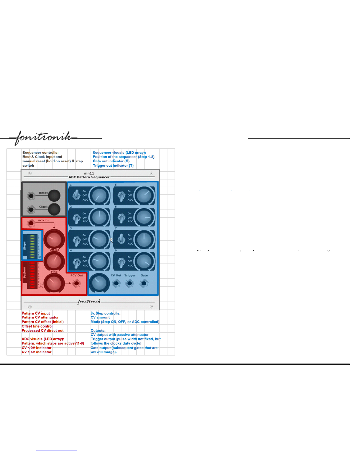
Sequencer controls:
Clock input and manual step button:
Apply
a clock signal here (i e LFO) It is
Clock
input
and
manual
step
button:
Apply
a
clock
signal
here
(i
.
e
.
LFO)
.
It
is
great if you have a clock with PWM. Why? Just because the width of the
sequencers trigger output pulses follows the clocks pulse width.
Reset input and manual reset button: When high the sequencer resets to step
on. As long as the reset is high, the sequencer will not step forward.
8x Ste
p
controls
,
Out
p
uts
,
se
q
uencer visuals:
p,p,q
For each step there is a knob to set the CV output value, and a mode switch
to set this steps status (ON, OFF, ADC). Whenever the sequencer steps to an
active step the set CV value, a gate (as long as the whole step, consecutive
gates merge), and a trigger (as long as the clock signal) will be available on
the outputs.
There is a passive attenuator for the CV output.
For inactive steps 0V will be seen on the CV output.
For all steps that are in ADC mode the status will be set by the ADC module
to the left (red).
The u
pp
er
y
ellow LED-
A
rra
y
tells
y
ou what the actual se
q
uencer is doin
g
: it
pp y
yy q g
indicates the current step, and if a gate or trigger output is active.
ADC module:
Here voltages are converted to an 8-bit code (hex). This voltage can be set
manually (Offset, Fine), or one could use an external pattern control voltage
(
PCV
)
. The PCV in
p
ut has an attenuator.
() p
The actual ADC wants to see 0-5V. To keep your pattern control voltages in
this window the attenuator and the offset controls form a voltage processor.
This processed voltage is also available at the PCV out.
Each of this 8 bits corresponds to one of your sequencers steps. If it is “I” it
would set the corresponding step to ON, if it is “O” it would set it to OFF (if this
steps mode switch is set to ADC, of course!).
Think this 8-bit code as a pattern: IIOIIOIO (and all possible 256 combi-
nations can be achieved)
The lower red LED-Array shows the actual pattern (depending on your mode
switch and PCV settings), and below that it provides two warning LEDs (PCV
0)
©2012 www.fonitronik.com page 1
<
0
V or >+5V
)
.
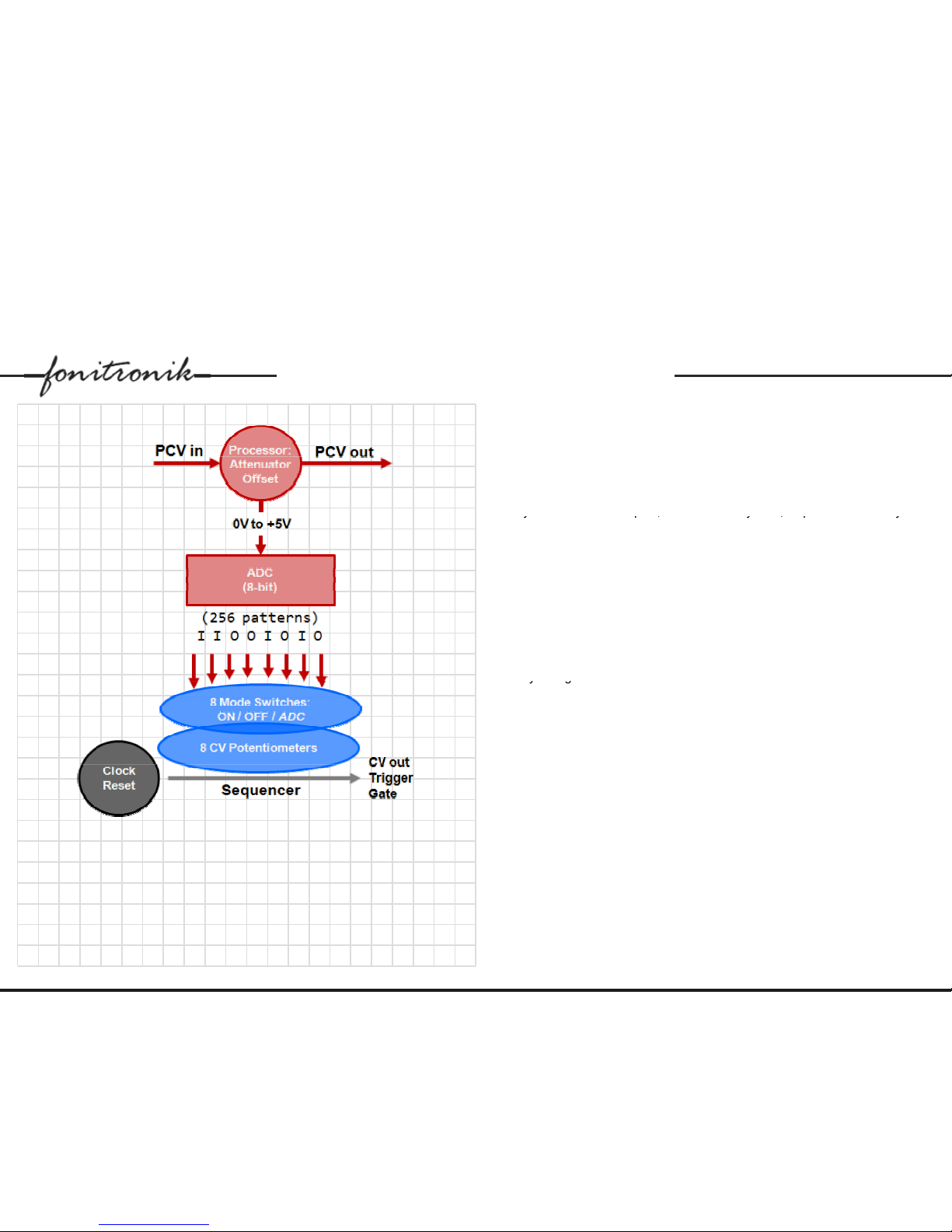
Refer to block diagram on next page also.
mh11 – ADC Sequencer – Quick Start
music electronics made in germany
Block Diagram:
The functional diagram to the left illustrates how the ADC module works
The
functional
diagram
to
the
left
illustrates
how
the
ADC
module
works
together with the actual 8-step sequencer.
The mode switches for each step are the actual link. Here you can tell each
step if it is always ON, OFF, or controlled by the corresponding bit of the 8-bit
pattern that is currently dialled in.
So
y
ou could i.e. set ste
p
s 1
,
4 and 7 to alwa
y
s ON
,
ste
p
2 and 8 to alwa
y
s
yp,y,py
OFF, whereas the other steps are controlled by the ADC module.
To understand what's happening, feed the mh11 a clock and set all step
switches to the up/ ON position. All steps play. Then 'mute' certain steps by
setting the switch to the OFF position. The ADC is used to automate this
muting - it generates an 8-bit string of ON & OFF values which is AND gated
()
with the incoming clock
(
Trig out
)
. To test this, stop the sequencer, set all
switches down to the ADC position and turn the manual PCV pot until all
lights of the pattern LED-bar are lit. Restart the sequencer and turn the
pattern knob. Any incoming CV is summed with the manual offset to generate
a new string of ON & OFF values. The ADC 're-computes' the pattern with
ever
y
chan
g
e.
yg
Important notes:
Avoid feeding the ADC with voltages higher than 8V. It might hang up and
need a power off, power on. Just use the PCV input attenuator!
The CV output voltage for inactive steps (OFF) is 0V So if you wanted to
The
CV
output
voltage
for
inactive
steps
(OFF)
is
0V
.
So
if
you
wanted
to
keep the CV of the previous step you will need a sample and hold.
The output CV droops slightly when passively multed (especially when the
passive attenuator on the CV out is used), so you may want to buffer it.
©2012 www.fonitronik.com page 2
mh11 – ADC Sequencer – Quick Start
music electronics made in germany
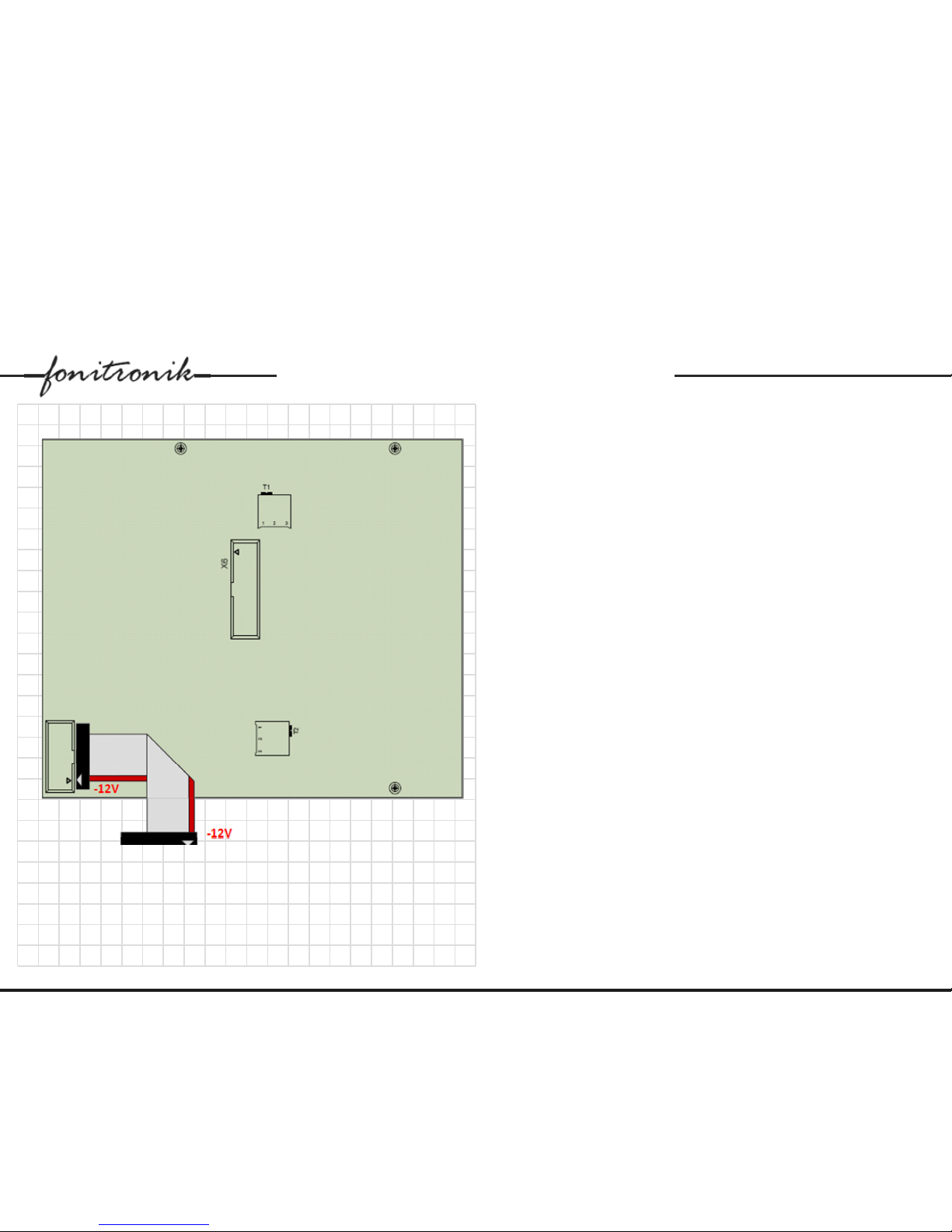
Service notes:
Precision trimmer
T1
sets the reference voltage for the ADC It is set up
Precision
trimmer
T1
sets
the
reference
voltage
for
the
ADC
.
It
is
set
up
correctly when in ADC-mode all steps are ON as soon as the PCV (pattern
control voltage) reaches +5V.
Precision trimmer T2 sets the delay time for the clock signal before it gets
used to create the trigger signal by ANDing the clock with the internal gates
(compensation of the propagation delay).
Both trimmers are set correctly by default.
The socket X6 is for connecting an expander module (not released yet). Here
the current pattern is available. Don’t connect anything if you don’t know what
you do. If you need more technical information, contact fonitronik.
Connecting the module to the Doepfer Eurorack-Buss:
The module comes with a ribbon cable. The sockets are hardware coded, and
follows the Doepfer-Standard (red wire = -12V). There is an additional sticker
on the PCB to show the pin out..
Technical data:
Current draw: +70mA/-20mA max, 3U, 24HP, Installation depth: 1.8in
NO MICROCONTROLLER, JUST ANALOG (so no firmware updates)
Disclaimer:
If you connect the module the wrong way it can be
damaged or destroyed. We cannot take any responsibility
in such a case. So triple-check all connections before
powering up the system
powering
up
the
system
..
Thanks for buying and using this module. Enjoy!
Cheers,
©2012 www.fonitronik.com page 3
Matthias Herrmann
______________________________________________________________
fonitronik * Am Hinkelhaus 31 * 65207 Wiesbaden * Germany
Table of contents


