manuals.online logo
Brands
  1. Home
  2. •
  3. Brands
  4. •
  5. M2SYNTH
  6. •
  7. Recording Equipment
  8. •
  9. M2SYNTH SV VCF 112 User manual

M2SYNTH SV VCF 112 User manual

SV VCF 112 V1c 1
SV VCF 112
Kit Assembly Instructions
SV VCF 112 V1c 2
Features
•1 Volt / Octave cut-off frequency CV for each filter type plus a common CV input that
controls all filters at once.
•Resonance potentiometer control with external CV control (controls all filter types)
•Each filter type has its own output
•A 4-channel output mixer blends the outputs of all 4 filter types to a common output
•Switches control the HP, BP and AP filter input route - off, main input signal or the LP
filter output
Kit Contents
Description
Reference
MOTM
Qty
MU
Qty
Notes
Components Kit
7216-112-1
1
1
See BOM
Accessories Pack including:
7216-112-2
1
1
Pot Sticky Pads
7210-188
14
14
10mm M4 Spacers
7210-186
5
5
M4 x 14 Cap Head Screws
7210-187
5
5
Toggle Switch Dress Nut
7210-196
3
3
M3 x 8mm Stainless Panel Screws
7216-151
4
8-Pin IC Socket
7212-331
6
6
18-Pin IC Socket
7212-334
4
4
Power Lead
7216-164
1
MOTM Front Panel
7216-512
1
Black
MOTM Back Panel
7216-812
1
MU Front and Back Panel
7219-512
1
Main PCB
7216-012
1
1
Jack Socket PCB
7215-703
1
1
Jack Socket PCB
7215-731
1
1
Jack Sockets
7216-612
1
1
Pack of 12
B100k Pots Long Shaft Angled
7216-710
1
Pack of 10
B100k Pots Short Shaft Angled
7216-740
1
Pack of 10
A100k Pots Long Shaft Angled
7216-724
1
Pack of 4
A100k Pots Short Shaft Angled
7216-754
1
Pack of 4
KM20B Knobs
7212-114
1
Pack of 14
MU Knobs
7219-114
1
Pack of 14
General Assembly Guidance
Booklet
1
1
BOM
S-7216-012-c
1
1
Circuit Schematic
S-7216-012-c
1
1
PCB Layout
S-7216-012-c
1
1
SV VCF 112 V1c 3
Assembly Instructions
The SV VCF module has no particular requirements not already covered in the ‘General
Guidance on a M²Synth Module Assembly’ booklet included with this kit.
Calibration
1. Power up module and allow to ‘warm up’ for 10 minutes
2. Connect a CV source to the Common CV input, a scope and frequency meter to the
Mix Out
3. Set all toggle switches to the down ‘Signal In’ position, all pots fully CCW
4. The V/octave is set for each individual filter. If the frequency is flat (<target), use the
specified trimmer and make the frequency lower (flatter), if above target frequency,
use the trimmer to make the frequency even higher, this can be counter-intuitive.
You will soon get the feel of how much to increase or decrease the frequency by
5. LP Filter –LP Mix pot fully CW, Resonance pot fully CW, CV to 0V
6. Adjust LP Cut-Off to giver an output self-oscillating frequency of 50Hz
7. Set CV to 5V, output frequency should be 1.6kHz, if not adjust PR1 as described in
step 4
8. Repeats steps 5-7 until 1.6kHz, then set LP Mix pot fully CCW
9. HP Filter –HP Mix pot fully CW, Resonance fully CW, CV to 0V
10. Adjust HP Cut-Off to giver an output self-oscillating frequency of 50Hz
11. Set CV to 5V, output frequency should be 1.6kHz, if not adjust PR2 as described in
step 4
12. Repeats steps 9-11 until 1.6kHz, then set HP Mix pot fully CCW
13. BP Filter –BP Mix pot fully CW, Resonance fully CW, CV to 0V
14. Adjust HP Cut-Off to giver an output self-oscillating frequency of 20Hz
15. Set CV to 5V, output frequency should be 640Hz, if not adjust PR3 as described in
step 4
16. Repeats steps 13-15 until 640Hz, then set BP Mix pot fully CCW
17. BP Filter –BP Mix pot fully CW, Resonance fully CW, CV to 0V
18. Adjust HP Cut-Off to giver an output self-oscillating frequency of 20Hz
19. Set CV to 5V, output frequency should be 640Hz, if not adjust PR3 as described in
step 4
20. Repeats steps 17-19 until 640Hz, then set BP Mix pot fully CCW
21. AP Filter –AP Mix pot fully CW, Resonance fully CW then back off until you get a
clean sinewave, CV to 0V
22. Adjust AP Cut-Off to giver an output self-oscillating frequency of 20Hz
23. Set CV to 5V, output frequency should be 640Hz, if not adjust PR4 as described in
step 4
24. Repeats steps 21-23 until 640Hz, then set AP Mix pot fully CCW
If at any time, you cannot set the initial starting frequency (50Hz or 20Hz) then adjust the
corresponding trimmer to bring it into range.
SV VCF 112 V1c 4
Specification
•Supply voltage +/-12Vdc or +/-15V if using the external voltage regulator
•Supply current +40mA / -55mA
•Waveform levels +/-5V
•Main PCB dimensions 131.95x174.05mm
Need tech support, post questions on our forum hosted by modwiggler.com

Other M2SYNTH Recording Equipment manuals

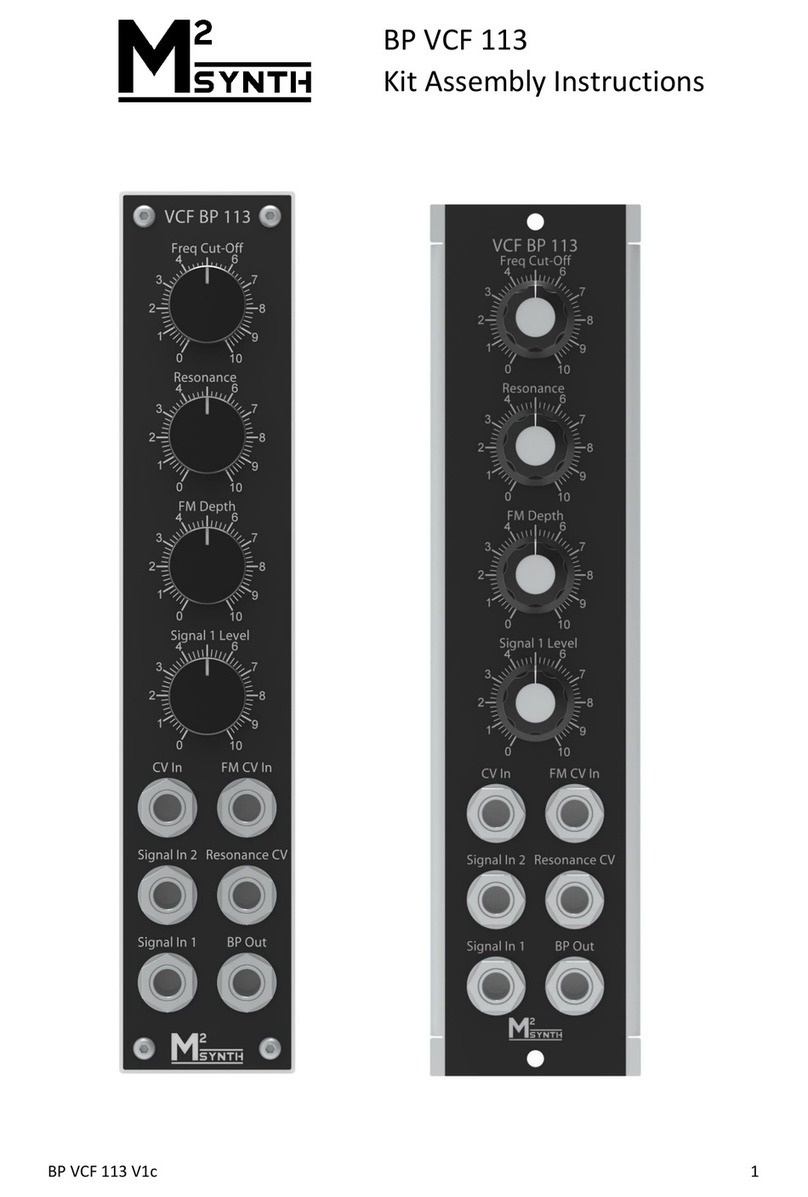
M2SYNTH BP VCF 113 User manual

M2SYNTH

M2SYNTH BP VCF 113 User manual

M2SYNTH BR VCF 114 User manual

M2SYNTH

M2SYNTH BR VCF 114 User manual

M2SYNTH VCLFO 105 User manual

M2SYNTH

M2SYNTH VCLFO 105 User manual

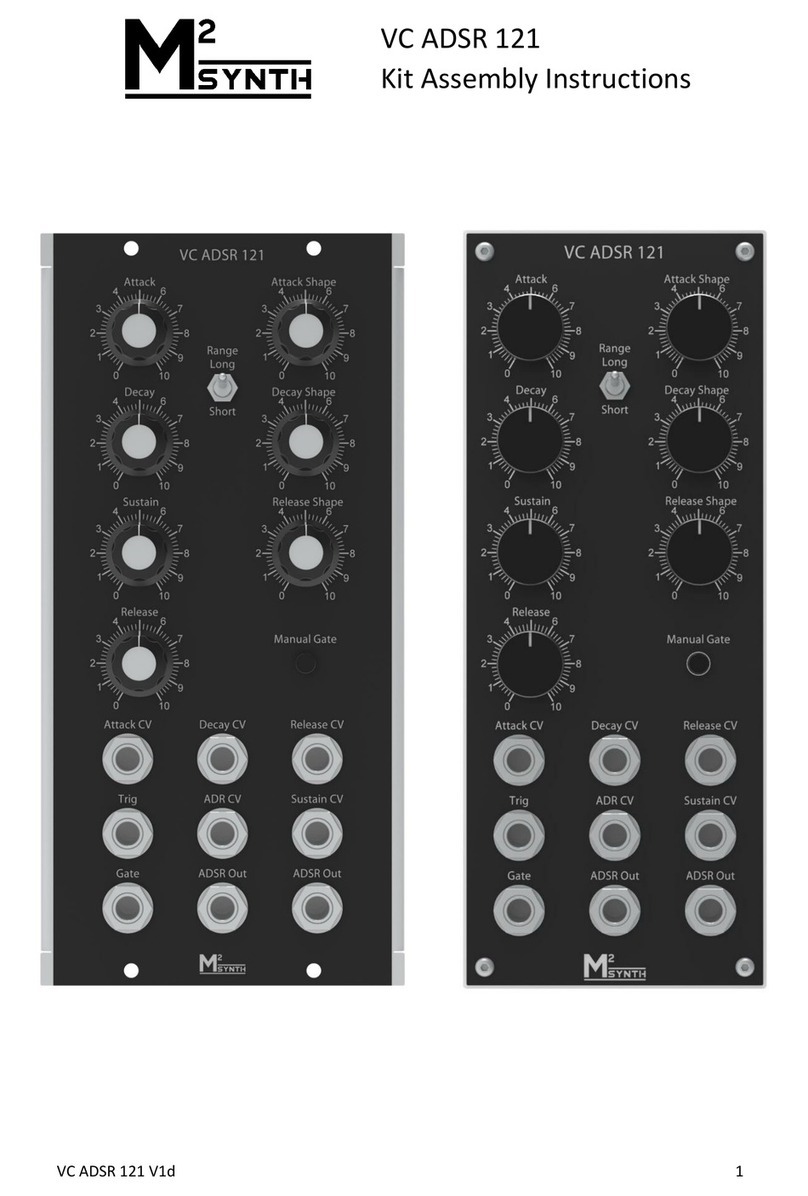
M2SYNTH VC ADSR 121 User manual

M2SYNTH

M2SYNTH VC ADSR 121 User manual

M2SYNTH Voice 108 User manual

M2SYNTH

M2SYNTH Voice 108 User manual

M2SYNTH HP VCF 111 User manual

M2SYNTH

M2SYNTH HP VCF 111 User manual

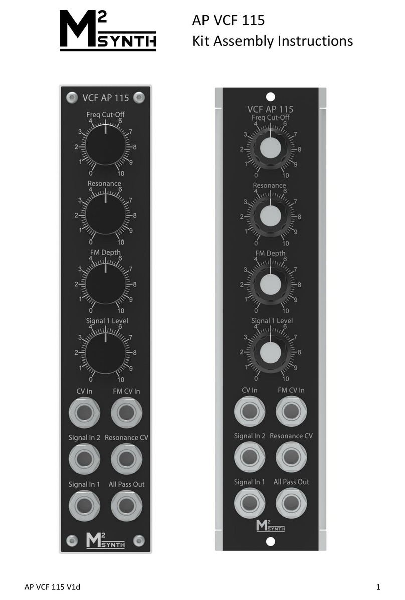
M2SYNTH AP VCF 115 User manual

M2SYNTH

M2SYNTH AP VCF 115 User manual

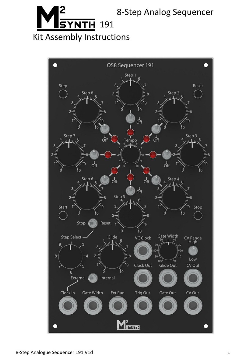
M2SYNTH 191 User manual

M2SYNTH

M2SYNTH 191 User manual

M2SYNTH Ring Modulator 151 User manual

M2SYNTH

M2SYNTH Ring Modulator 151 User manual

Popular Recording Equipment manuals by other brands

Zoom H4N user guide

Zoom

Zoom H4N user guide

Truma iNet Box operating instructions

Truma

Truma iNet Box operating instructions

Franklin DRP-3000 AnyBook Reader user guide

Franklin

Franklin DRP-3000 AnyBook Reader user guide

Extron electronics VN-Matrix user guide

Extron electronics

Extron electronics VN-Matrix user guide

Akai EWI 1000 Service manual

Akai

Akai EWI 1000 Service manual

Musicom Lab MVC user manual

Musicom Lab

Musicom Lab MVC user manual

Kvaser Memorator Pro 2xHS v2 CB user guide

Kvaser

Kvaser Memorator Pro 2xHS v2 CB user guide

Yamaha REV7 operating manual

Yamaha

Yamaha REV7 operating manual

ARX DI-PLUS 2 owner's manual

ARX

ARX DI-PLUS 2 owner's manual

Endress+Hauser Commubox FXA195 technical information

Endress+Hauser

Endress+Hauser Commubox FXA195 technical information

Elation AR-32 user manual

Elation

Elation AR-32 user manual

Roland Rhythm Composer TR-505 owner's manual

Roland

Roland Rhythm Composer TR-505 owner's manual

Panasonic WJHD100 - DIGITAL DISC RECORDE operating instructions

Panasonic

Panasonic WJHD100 - DIGITAL DISC RECORDE operating instructions

Ecler DAM514 user manual

Ecler

Ecler DAM514 user manual

Microtrol Black Pear TXIO Installation and user guide

Microtrol

Microtrol Black Pear TXIO Installation and user guide

Cochlear Baha 5 SuperPower user manual

Cochlear

Cochlear Baha 5 SuperPower user manual

Zoom H4n Pro operating instructions

Zoom

Zoom H4n Pro operating instructions

Peavey PC 1600 manual

Peavey

Peavey PC 1600 manual

manuals.online logo
manuals.online logoBrands
  • About & Mission
  • Contact us
  • Privacy Policy
  • Terms and Conditions

Copyright 2025 Manuals.Online. All Rights Reserved.