Pub. 42004-525A
GAI-TRONICS®
A H U B B E L L C O M P A N Y
Model 370-901 SP2 to Page/Party® Bridge
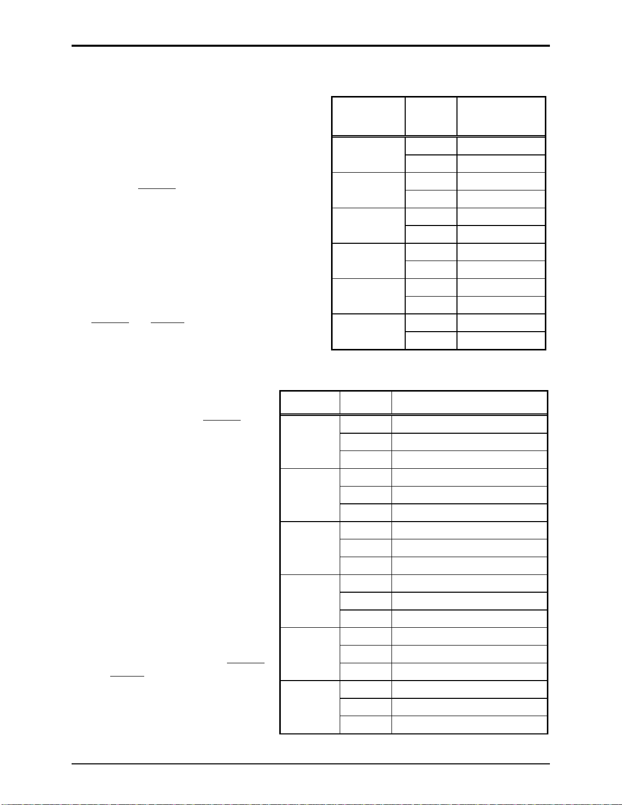
TA B L E O F CO N T E N T S
GAI-TRONICS 3030 KUTZTOWN RD. READING, PA 19605 USA
610-777-1374 800-492-1212 Fax: 610-796-5954
VISIT WWW.GAI-TRONICS.COM FOR PRODUCT LITERATURE AND MANUALS
Confidentiality Notice.....................................................................................................................1
General Information.......................................................................................................................1
Features....................................................................................................................................................1
Option ......................................................................................................................................................1
Installation ......................................................................................................................................2
Important Safety Instructions................................................................................................................2
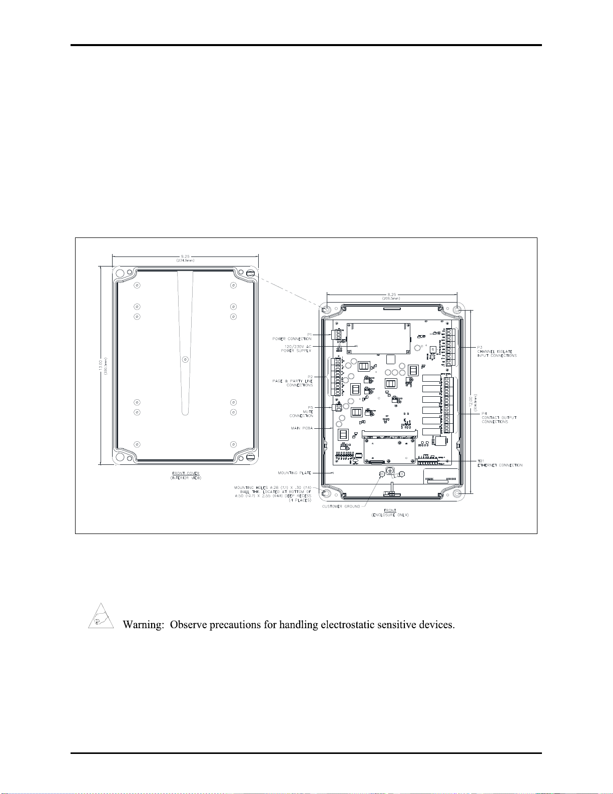
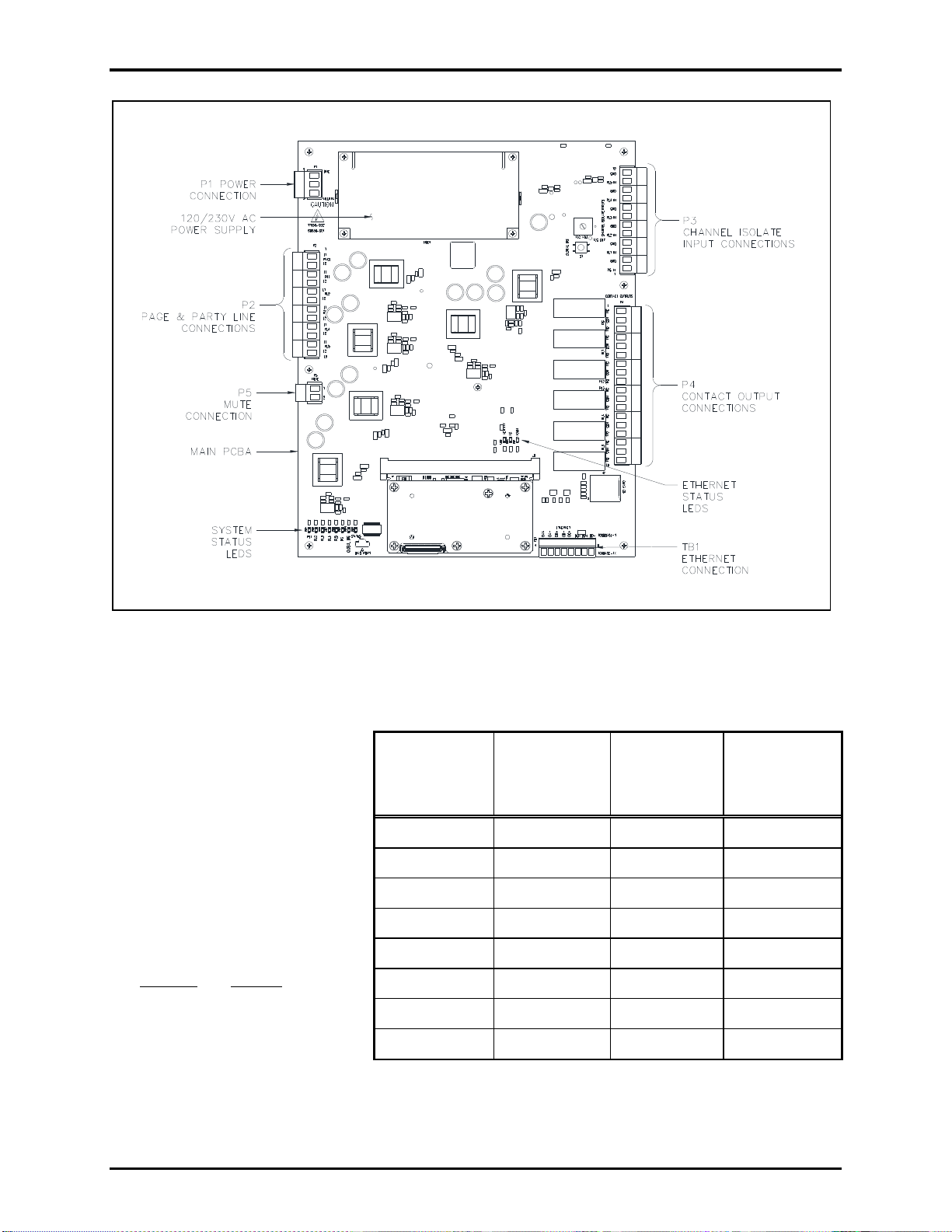
Open the Enclosure.................................................................................................................................2
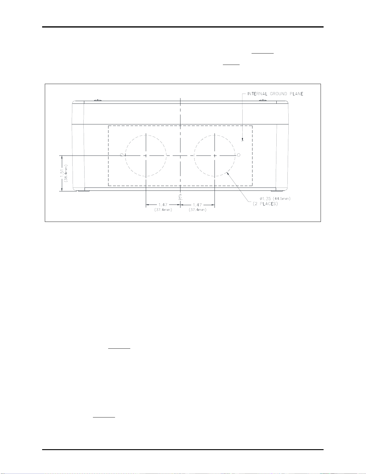
Mount the Enclosure...............................................................................................................................3
Field Terminations..................................................................................................................................3
Earth Ground.........................................................................................................................................3
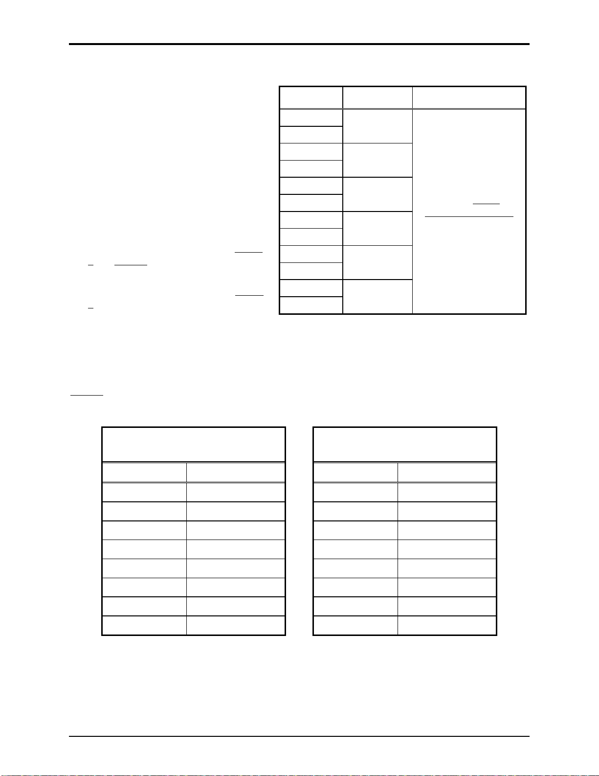
Ethernet—TB1......................................................................................................................................4
Page/Party®33-Ohm Audio Connections—P2.....................................................................................5
60029 Series Page/Party®System Cable...............................................................................................5
Channel Isolation Inputs—P3...............................................................................................................6
Contact Outputs—P4............................................................................................................................6
Mute Connection—P5 ..........................................................................................................................7
Power—P1............................................................................................................................................7
Close the Enclosure.................................................................................................................................7
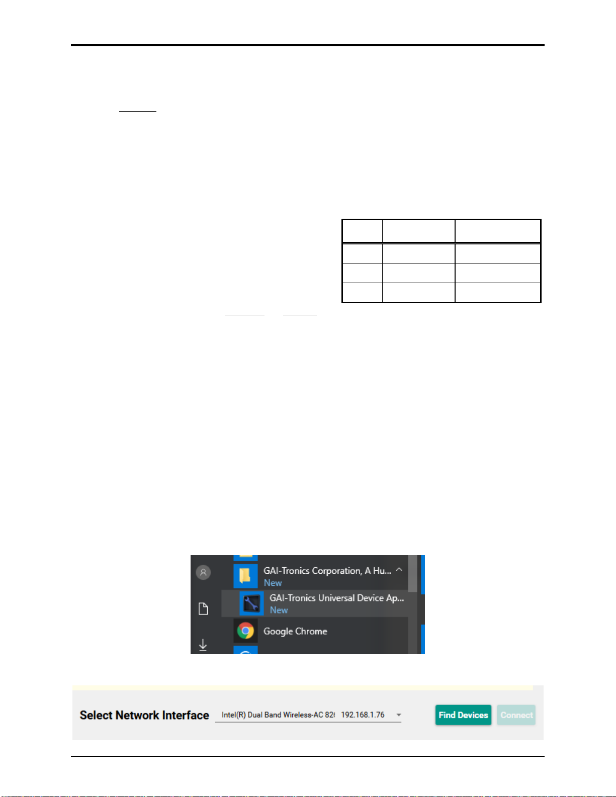
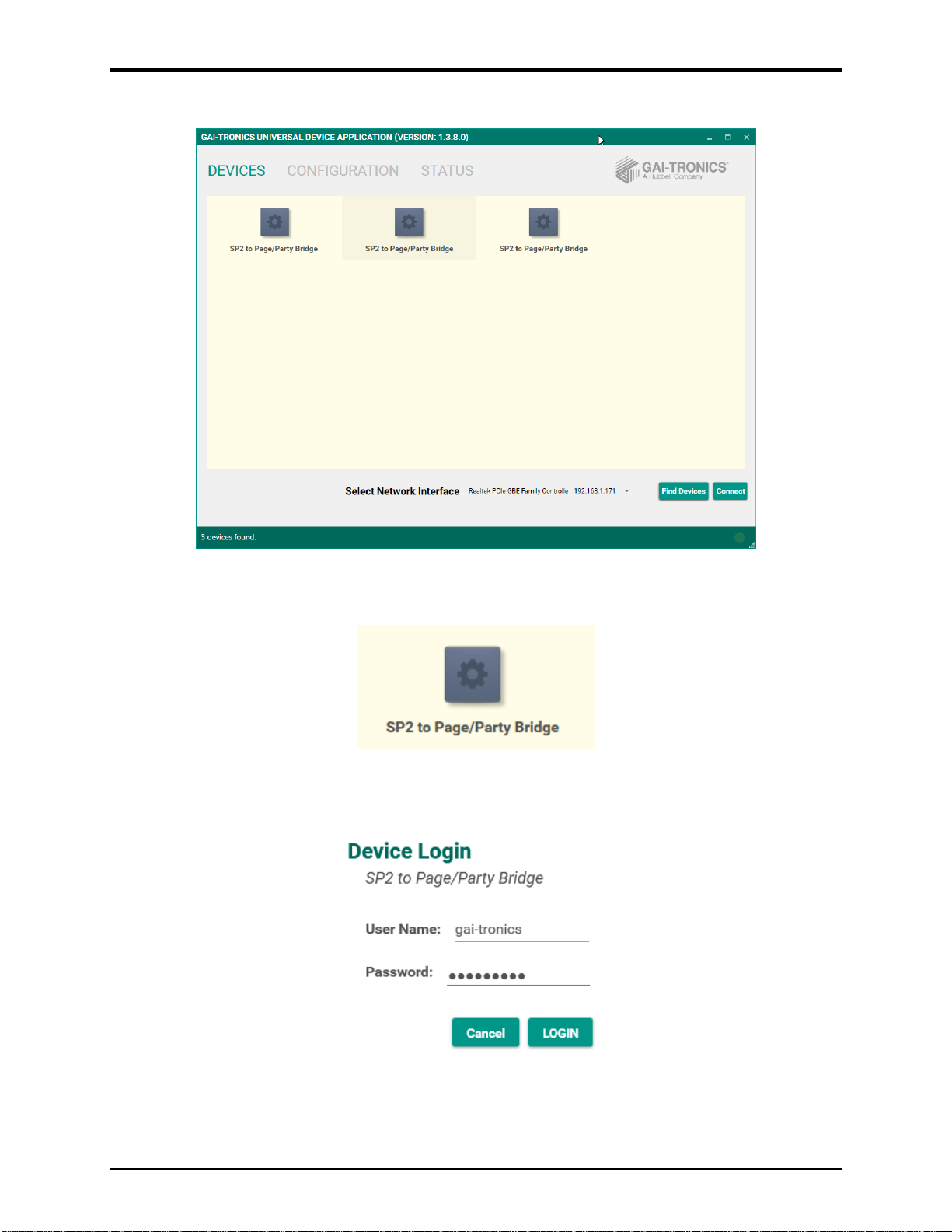
Configuration..................................................................................................................................7
Interface Configuration..........................................................................................................................9
Channel Configuration.........................................................................................................................10
GUDA Status.........................................................................................................................................11
Interface Status....................................................................................................................................11
Channel and Redundant Channel Status............................................................................................. 12
Operation.......................................................................................................................................12
Global Disable.......................................................................................................................................12
System Reset..........................................................................................................................................13
System Status LEDs..............................................................................................................................13
Ethernet Status LEDs...........................................................................................................................13
Maintenance..................................................................................................................................13
GUDA Device Administrator Options ................................................................................................14
Save Configuration Locally..................................................................................................................14
Import Saved Configuration................................................................................................................15