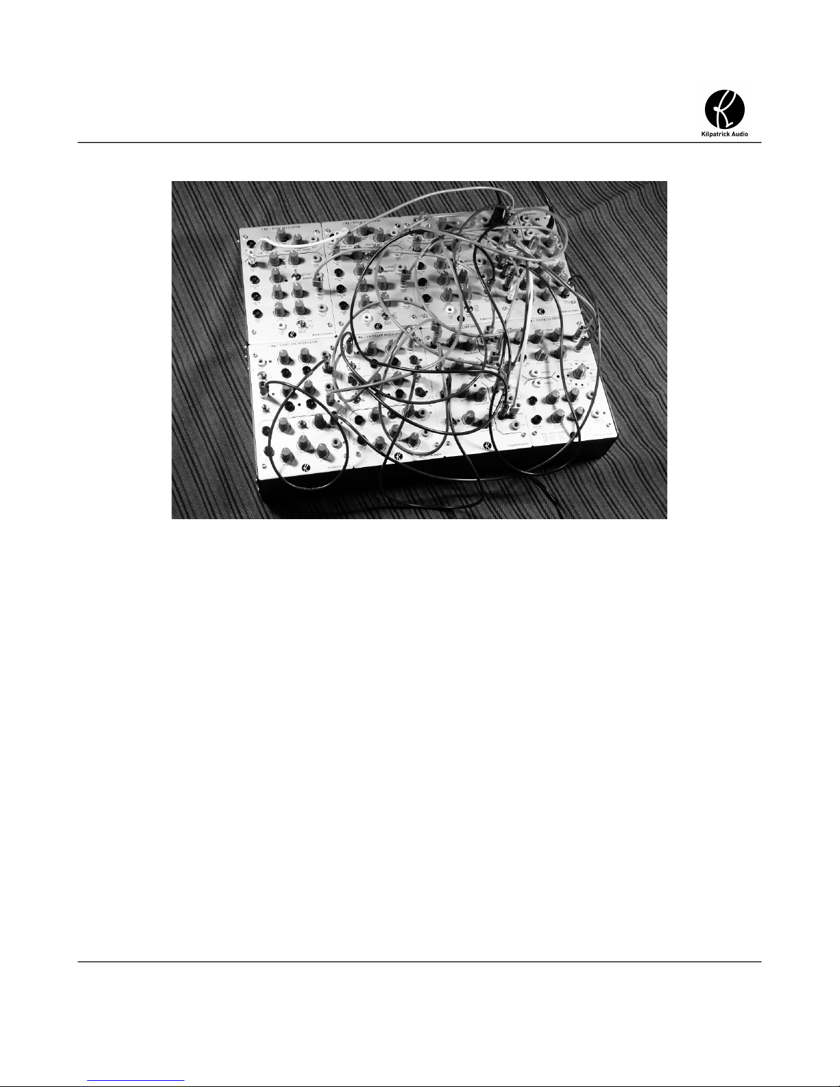
Kilpatrick Audio Format User manual

Kilpatrick Format
Technical Specications
Kilpatrick Format
Technical Specifications
A Specification and Guide for Module Designers
Copyright 2014: Kilpatrick Audio Andrew Kilpatrick
Written by: Andrew Kilpatrick
07/02/2014 Page 1 of 29
web: www.kilpatrickaudio.com – email: info@kilpatrickaudio.com

Kilpatrick Format
Technical Specications
Table of Contents
Introduction................................................................................................................................................4
A Few Words of Welcome.....................................................................................................................5
Use of the Kilpatrick Format Specification...............................................................................................6
Namin Requirements...........................................................................................................................6
Keep Kilpatrick Audio Informed...........................................................................................................6
Errors, Omissions and Su estions.......................................................................................................6
Physical Specifications..............................................................................................................................7
Module Stack-up Overview...................................................................................................................7
Panel Material........................................................................................................................................8
Panel Retainin Screw...........................................................................................................................9
Module Power Plu s...........................................................................................................................10
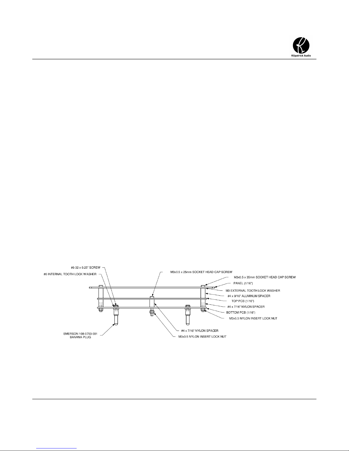
Module Stack-up Details.....................................................................................................................11
Panel Dimensions and Thickness........................................................................................................12
PCB Dimensions and Thickness.........................................................................................................12
Panel to Top PCB Spacin ..................................................................................................................12
Top PCB to Bottom PCB Spacin .......................................................................................................13
Enclosures................................................................................................................................................14
Module Mountin Plate.......................................................................................................................15
Power Supply......................................................................................................................................16
Active / Passive Enclosure Interconnect.............................................................................................17
Connectin Multiple Active Enclosures..............................................................................................17
Power Wirin and Power Supplies...........................................................................................................18
Analo and Di ital Grounds................................................................................................................18
System Power Groundin ....................................................................................................................19
Power Supplies on Modules................................................................................................................19
Audio and Control Si nals.......................................................................................................................20
Si nal Impedance................................................................................................................................20
Input and Output Volta e Ran e.........................................................................................................20
Gates and Pulses..................................................................................................................................21
Audio and CV Si nals.........................................................................................................................21
Indicator LEDs.........................................................................................................................................21
Module Desi n Techniques......................................................................................................................22
Module Power Supply Example..........................................................................................................22
Pulse Input Circuit...............................................................................................................................23
+3.3V to +5V Pulse Amplifier.............................................................................................................24
Bi-colour LED Driver.........................................................................................................................25
07/02/2014 Page 2 of 29
web: www.kilpatrickaudio.com – email: info@kilpatrickaudio.com

Kilpatrick Format
Technical Specications
Split Supply Usin an Opamp.............................................................................................................26
Goin Between AGND and DGND....................................................................................................27
Appendix A – Part Reference...................................................................................................................28
Appendix B – Module Reference Drawin s............................................................................................29
Appendix C – Enclosure and Power Supply Drawin s...........................................................................29
07/02/2014 Page of 29
web: www.kilpatrickaudio.com – email: info@kilpatrickaudio.com

Kilpatrick Format
Technical Specications
Introduction
The Kilpatrick Format is a unique and flexible modular synthesizer format with many useful features.
The format can be applied to modular synthesizers, audio equipment, li htin and video system, and
any system where low-power modules, strai ht-forward module desi n, hi h quality construction and
easy module installation and removal is desirable.
Main Features:
•4U (7”) panel height - makes desi nin attractive and functional modules enjoyable
•Easy Plug-in System - makes installin and removin modules easy – no panel screws used
•Simple module construction – improves desi n work flow and removes uess-work – all
modules fit all enclosures
•Improved Electrical Properties – 15V rails plus separate analo and di ital rounds provide a
better electrical environment for circuit desi ners
•Banana Cables for Patching – the use of standard banana connectors offer a hi h quality,
stackable, colour-coded connector which is low-cost and easy to assemble on PCBs
•Off-the-Shelf Components – no custom connectors or toolin means parts are available from
most distributors
07/02/2014 Page 4 of 29
web: www.kilpatrickaudio.com – email: info@kilpatrickaudio.com

Kilpatrick Format
Technical Specications
A Few Words of Welcome
On behalf of Kilpatrick Audio I thank you for taking the time to get to know more about the Kilpatrick
Format. After many years searching for the “ultimate” format for my own designs I developed the
Kilpatrick Format to solve a number of problems I saw when designing for other modular systems.
After e perimenting with 5U Modcan style and 3U Eurorack formats and being frustrated by both, I
realized that 4U is the “right” size for modular synths. Buchla and Serge definitely had it right, and
although I could have copied their proprietary formats, there were aspects that bothered me.
I finally came up with what I feel lends itself to easy module design. Products can be built in small
quantities. (important if you want to offer a lot of modules on a built-to-order basis) It has good
electrical characteristics, feels good physically, and uses all off-the-shelf parts which should make
boutique designs somewhat future-proof. The enclosure and power supply design are low-cost and
reliable.
I hope that you are inspired to make your own modules in the Kilpatrick Format and I look forward to
seeing and hearing what you come up with!
Andrew Kilpatrick - 2014
07/02/2014 Page 5 of 29
web: www.kilpatrickaudio.com – email: info@kilpatrickaudio.com

Kilpatrick Format
Technical Specications
Use of the Kilpatrick Format Specification
The oal of this specification is to encoura e the use the Kilpatrick Format by both commercial
manufacturers and DIY builders. Please follow the specification as closely as possible, or contact
Kilpatrick Audio if your needs are not accounted for here. With so many low-quality products available
for other formats, strict compatibility is necessary to maintain the quality of the system. If your oal is
to make the cheapest possible products then please choose a different format. However, if you want to
make excellent modules that are cost-effective and very hi h quality then you are probably in the ri ht
place!
Naming Requirements
Somewhere within your advertised specifications, you must indicate that your product is a “Kilpatrick
Format” module or accessory. Use of the name means that the module or accessory meets the
requirements set out within this specification, or whichever version of the spec is current at the time
you undertake your desi n. This help customers who purchase modules to know that they are ettin a
quality product that will work well with existin and future module desi ns from other manufacturers.
Keep Kilpatrick Audio Informed
Use of the Kilpatrick Format is free of char e, but you must tell us if you release a module so that we
can keep track of products available in the format. We will also offer a module swap service so that
builders can put to ether nice systems at low cost. When you have a module ready let us know and
we'll arran e to swap a module of similar value with yours. We hope you will extend this opportunity to
other builders as well.
If you don't want to trade modules, sendin some info that we can post on our website would be reat
also. We are interested in linkin to both commercial and DIY sites if you want to become part of the
family. Prospective buyers often ask what other modules are available.
Errors, Omissions and Suggestions
Please help to improve this specification by reportin any errors, information that is missin or difficult
to understand, and any other ideas that would help to improve it.
07/02/2014 Page 6 of 29
web: www.kilpatrickaudio.com – email: info@kilpatrickaudio.com

Kilpatrick Format
Technical Specications
Physical Specifications
The Kilpatrick Format is built around panels which are one or more spaces wide. A space is set as 1/4
of a rack width, and 4U (7”) tall. Four spaces occupy one rack-mountable enclosure. Wider enclosures
are possible, with 5 or 6 spaces bein the most useful. Spaces are 4.250" x 7.000", but panels are
manufactured as 4.240" x 6.990" to compensate for sli ht manufacturin tolerances and also ali nment
when the modules are plu ed into the system. The dimensions should be reduced by 0.005” on each
ed e so that all holes, etc. are centered within the panel.
One and two space panels are the most useful sizes, althou h three and four spaces can be made as
well. You must not make modules wider than four spaces because all modules should fit into a
rack-mounted enclosure. The corners of modules are always rounded with a 0.125” radius to make
them less sharp and also hide small ali nment problems when the modules are sittin next to each
other. If you have an idea for a hu e module it mi ht make more sense to break it up into several
smaller desi ns.
odule Stack-up Overview
Before we o into detail on the each part of a module, have a look at the followin dia ram which
shows the components of a module as a section view. All modules are built with the same stack-up and
spacin between layers.
07/02/2014 Page 7 of 29
web: www.kilpatrickaudio.com – email: info@kilpatrickaudio.com
Fig 1 - Module Stack-up – Side View

Kilpatrick Format
Technical Specications
The spacin s are chosen to allow the use of common components such as banana jacks, to le
switches, board to board stackin headers, etc. Some components like pushbuttons and some kinds of
jacks may require additional PCBs or different spacin s, but for most modules the su ested spacin
should offer the most flexibility.
Panel aterial
Panels are enerally made from 14GA (0.062" or 1/16” thick) anodized aluminum. Kilpatrick panels
are vertically brushed and anodized and screened with black epoxy ink. Other finishes are acceptable
such as powder coatin . Panels must be made from metal. The panel thickness must be 0.062” to
ensure that all module faces are ali ned when installed in a system.
Note: The use of PCB material or acrylic as a panel material is not acceptable. If these materials
are required for specific reasons, they should be installed within an area of a metal panel and not
used to support the banana jacks or mountin bolts.
07/02/2014 Page 8 of 29
web: www.kilpatrickaudio.com – email: info@kilpatrickaudio.com
Fig 2 - Raw Panels

Kilpatrick Format
Technical Specications
Panel Retaining Screw
Below each module space in an enclosure is a blind M3x0.5 standoff used to secure a module to the
enclosure. Each module must contain a captive M3x0.5 x 25mm hex head cap bolt that uses a 2.5mm
hex key. The bolt is installed between the two PCB layers with a spacer between PCBs. The retainin
feature is accomplished by a nylon insert lock nut underneath the PCB. A hole in the top panel ives
access to the bolt. The module can be secured by ently ti htenin the bolt. When banana cables are
pulled out many at a time, the bolt keeps the module from pullin out of the enclosure. In production
the nut should be ti htened part way to allow some play in the bolt. The spacer prevents
over-ti htenin and dama e to the PCBs.
07/02/2014 Page 9 of 29
web: www.kilpatrickaudio.com – email: info@kilpatrickaudio.com
Fig 3 - Retaining Screw – Side View

Kilpatrick Format
Technical Specications
odule Power Plugs
The main parts that secure a module into an enclosure are the power plu s. The plu s are male banana
plu s of the same type used for panel patchin . These are available as metal plu s supplied with #6-32
bolts which screw into the back of the plu . Four plu s are secured to the PCB usin additional internal
toothed lock washer on the top side of the lower PCB. Locktite blue (medium stren th) is used
sparin ly on each bolt to help keep the bolts from loosenin , but not enou h to prevent ood electrical
contact as the bolts are used to couple power to the lower PCB.
The plu s supply the four power si nals: +15V, -15V, AGND and DGND. Note that the AGND plu is
ali ned differently, thus providin a keyin to prevent backwards installation.
07/02/2014 Page 10 of 29
web: www.kilpatrickaudio.com – email: info@kilpatrickaudio.com
Fig 4 - Power Plugs – Bottom PCB - Top View

Kilpatrick Format
Technical Specications
odule Stack-up Details
The module stack-up is inte ral to the physical robustness and overall hei ht of a module. The module
assembly is desi ned to use standard components and be easy to assemble. The spacin between the
panel and PCBs is a compromise, but must be kept within a ti ht tolerance to avoid hei ht problems
when plu in the module into an enclosure.
Notes about the photo:
•LED spacers used throu hout
•banana jacks metal tab soldered to top PCB throu h 0.197” hole
•30mm pots and standard to le switches can be used
•shorter parts and specialty displays, etc. should use dau hter PCB mounted to top PCB
07/02/2014 Page 11 of 29
web: www.kilpatrickaudio.com – email: info@kilpatrickaudio.com
Fig 5: Module Stack-up - Side View

Kilpatrick Format
Technical Specications
Panel Dimensions and Thickness
The panels are nominally 14GA aluminum 0.062” (1/16”) thick. A brushin / anodizin operation
usually removes a small amount of material. The overall dimensions of a sin le-space panel is 4.240”
wide and 6.990” tall. Each of four corners is rounded off with a 0.125” (1/8”) radius. Detailed drawin s
can be found in Appendix B of this document.
PCB Dimensions and Thickness
All PCBs are nominally 0.062” (1/16”) thick. Includin 1oz copper and a solder mask this thickness is
actually about 0.067”. The overall dimensions of a sin le-space PCB is 4.100” wide and 6.100” tall.
Detailed drawin s can be found in Appendix B of this document.
Wider PCBs can be made for modules of 2-4 spaces. In the case of wider modules some of the power
connections can be omitted. For instance in a 3 space module power plu s are used on space 1 and 3
but not in the center (2) space. Similarly only two retainin bolts are used.
Panel to Top PCB Spacing
The spacin from the panel to the top PCB is nominally 0.562” (9/16”) plus the thickness of an M3
external tooth lock washer. The overall hei ht is approx. 0.587”. Round, un-threaded aluminum spacers
are used between the panel and top PCB to create a round connection to the top panel. The external
tooth lock washer ensures a ood connection since anodized panels are non-conductive on the surface.
The metal panel is always connected to AGND so that the entire system is shielded.
The spacin from the panel to the top PCB allows standard Emerson banana jacks to be soldered to the
top PCB. It also allows the use of standard mini to le switches. For shorter components like
pushbuttons, etc. a small sub-assembly PCB may be required to support these types of components
closer to the panel. How this is implemented is up to the desi ner.
07/02/2014 Page 12 of 29
web: www.kilpatrickaudio.com – email: info@kilpatrickaudio.com

Kilpatrick Format
Technical Specications
Top PCB to Bottom PCB Spacing
The spacin from the top PCB to the bottom PCB is nominally 0.437”. (7/16”) Nylon spacers are used
between the top and bottom PCBs for low-cost. A spacer is required in each of four corners plus one in
the center where the retainin screw is held captive.
Connectin si nals between the top and bottom PCBs is possible by usin standard 0.100” stackin
header connectors. Kilpatrick Audio uses 20 pin sin le-row connectors on all desi ns. The possible
location of the headers is chosen per desi n. Alternately a dual-row header could be used for denser
modules. The combination of a standard male and female header results in precisely 0.437” (7/16”)
spacin between PCBs.
When choosin stackin headers, the male header protrudes from the bottom of the top module, and the
female header protrudes from the top of the bottom module. This ensures that durin prototypin ,
assembly and testin , sensitive circuits on the bottom PCB do not have their pins exposed. Top PCBs
usually only contain passive parts and LEDs.
07/02/2014 Page 1 of 29
web: www.kilpatrickaudio.com – email: info@kilpatrickaudio.com
Fig 6: Module Stacking Headers

Kilpatrick Format
Technical Specications
Enclosures
Enclosures are desi ned to be low-cost and easy to manufacture in small quantities. The existin
Kilpatrick Audio enclosure and power supply desi n is offered for use free-of-char e and drawin s are
available in Appendix C of this document. These included drawin s are for reference only. For the
latest drawin s includin DXF or IGES files of the enclosure for metal manufacturers please contact
Kilpatrick Audio or see our website for download info.
07/02/2014 Page 14 of 29
web: www.kilpatrickaudio.com – email: info@kilpatrickaudio.com
Fig 7: Enclosure - 4 Space Active Enclosure

Kilpatrick Format
Technical Specications
odule ounting Plate
The main part of the enclosure serves only to cover the sides of the modules and provide mountin
points to attach rack ears or stackin brackets for connectin two enclosures to ether. The important
interface between the modules and the enclosure is throu h the module mounting plate. This part is
mounted in the bottom of the enclosure on 0.875” (7/8”) standoffs which provide an electrical
connection to the main enclosure, as well as supportin the plate at the correct hei ht for modules to be
installed. #6 internal tooth lock washers used between the top and bottom screws and the metal ensures
a ood electrical connection so that the entire chassis is rounded to AGND.
Notes about the photo:
•banana jack colours are:
◦+15V = red
◦-15V = rey
◦AGND and DGND = black
07/02/2014 Page 15 of 29
web: www.kilpatrickaudio.com – email: info@kilpatrickaudio.com
Fig 8: Module Mounting Plate - Top View

Kilpatrick Format
Technical Specications
Underneath the plate is ample room for wirin the module power jacks, inlet power socket, switch,
power LED, and the actual power supply PCB. The power supply is mounted upside-down on the
underside of the module mountin plate which protects it and the associated wirin .
Power Supply
The power supply is a very simple module usin an off-the-shelf DC-DC converter. The power input
must be re ulated +15V and is simply passed throu h a reverse polarity protection diode (Schottky
type) and filtered. This raw supply is fed to the +15V jack on every module. The on-board DC-DC
module produces -15V with 10W max. output. This is filtered and fed to the -15V jack on every
module.
This scheme offers limited -15V power (but plenty for most desi ns) but allows the +15V supply to be
increased simply by usin a lar er external power supply. For di ital modules that contain embedded
computers, for instance, it mi ht be necessary to have many watts of power on a sin le module. The
most economical route to this is to allow the end-user to up rade their external adapter. A 24W unit is
supplied by Kilpatrick Audio and is suitable for up to ei ht modules. The typical wirin in a system
should handle +15V at 40-60W (3-4A) without any trouble. The input protection diode for the system
is rated for up to 7.5A, and desi ners who wish to build their own power supplies should keep in mind
that users may want to up rade their +15V power supply at a later time for hi her power use.
Note: The use of un rounded (2-wire) external power supplies is preferred over rounded types. (more
on this below)
07/02/2014 Page 16 of 29
web: www.kilpatrickaudio.com – email: info@kilpatrickaudio.com
Fig 9: Module Mounting Plate Underside - Active Type

Kilpatrick Format
Technical Specications
Active / Passive Enclosure Interconnect
The enclosure is desi ned with front/rear and bottom cutouts to allow flexibility in wirin the DC
power and inter-enclosure power cables. Normally two enclosures are used to ether. The top one
contains the power supply and is called the active enclosure whereas the bottom enclosure is passive
and contains wirin only. Connectors on the module mountin plate allow a short cable to be attached
to the front or rear of the plate. Four wires are needed to connect active and passive enclosures to ether.
For very low-power modules such as MIDI controllers, it mi ht be possible to connect two or even
three passive enclosures to a sin le active enclosure. Passive enclosures can be installed above or
below the main enclosure, but enerally they are installed below because this allows better access to
the power input jack and power switch on the rear of the active enclosure.
An important note about roundin is that the di ital round (DGND) from all modules and enclosures
is returned to the power supply PCB where it is connected to analo round (AGND) at a sin le point.
This prevents round loops and noise from bein injected into sensitive circuits. AGND and DGND
must never be tied to ether except at the power supply PCB of an active enclosure.
Connecting ultiple Active Enclosures
If a system rows beyond ei ht modules it is likely to require more than one active enclosure. In this
case it is necessary to connect the round between the two systems. A black banana jack is provided on
the rear of each enclosure which is internally connected to AGND. A standard banana patch cable can
be used to connect multiple sets of enclosures to ether. Each active enclosure requires its own external
power supply.
07/02/2014 Page 17 of 29
web: www.kilpatrickaudio.com – email: info@kilpatrickaudio.com

Kilpatrick Format
Technical Specications
Po er Wiring and Po er Supplies
Power wirin within a system uses a simple methodolo y which keeps wires short. In most cases the
wirin between modules within a sin le enclosure are daisy-chained. These roups of jacks are then
attached to the connectors which feed to the next and previous enclosures, and to the power supply in
the case of an active enclosure.
The topolo y is not particularly important for the most part. The most crucial aspect is that analo
round (AGND) and di ital round (DGND) must be kept separate throu hout an entire system and
only joined to ether at a sin le point within the power supply. Systems with multiple powered
enclosures must have their analo rounds connected to ether. Each module has an analo round
connection (banana jack) on the back of the enclosure for this purpose.
Analog and Digital Grounds
For optimum CV and audio performance it is crucial that noisy si nals and lar er loads which switch
on and off not be allowed to interfere with sensitive si nals. Because banana cables are a sin le wire,
the si nal return (analo round) is provided inside the enclosure. Thus any noise on the internal return
will be added to the patched si nal. Lar e or noisy loads within a module that draw current in and out
of the round connection will cause volta e drops on the round wirin within a system which will be
added to CV and audio si nal paths.
The Kilpatrick Format system uses separate analo and di ital rounds (AGND and DGND) to solve
this problem. Analo rounds are used for si nal returns, references for analo circuits, ADCs and
DACs, and other low-noise circuits.
Di ital rounds are used for noisy circuits such as DC-DC converter rounds, microcontroller power
supplies, LED rounds and other loads that could be noisy. In most cases it is easy to keep these two
rounds separate except in a few cases which will be covered in detail in the Module Design
Techniques section.
Power supplies (+15V and -15V) are shared between both analo and di ital circuits. These supplies
are also not uaranteed to be quiet or particularly well re ulated meanin that they should never be
used to directly power sensitive circuitry. Instead every module uses local volta e re ulators and power
supplies to deliver volta es to the various sta es. A typical hybrid module containin both analo and
microcontroller circuitry mi ht have the followin supplies:
•+12V and -12V linear volta e re ulators for op amp supplies –fed from +15V and -15V
•+3.3V DC-DC buck converter for microcontroller power supply – fed from +15V
•+3.3V linear re ulator connected to the +12V supply for ADC and DAC power supplies
07/02/2014 Page 18 of 29
web: www.kilpatrickaudio.com – email: info@kilpatrickaudio.com

Kilpatrick Format
Technical Specications
System Power Grounding
One flaw of many modular systems is the use of a rounded power cord. Althou h this may be required
for re ulatory purposes, it often causes round loops and hum in typical systems. Almost always a user
will have a computer and/or a mixin console which will be rounded to the electrical supply. (third
pron ) Kilpatrick Audio uses power supplies that require only two wires. The audio cables provide a
round reference from the studio mixin console, and no round loops exist within the system.
In hi her power systems where a two pron power supply is not possible, or where the synthesizer is
the central mixin point for an entire system it may be preferable to use a rounded power supply. But
enerally power supplies with 2-pron input plu s will offer the best noise and hum performance in a
typical setup.
Power Supplies on odules
It is important that the volta e drop and tolerance of the main power supply and linear re ulators on
modules be taken into account. Kilpatrick Audio modules use Schottky diodes on both the main power
supply and also the +15V and -15V inputs on each module. This offers minimal volta e drop and
permits the use of standard linear volta e re ulators for +12V and -12V.
For +3.3V linear supplies for DACs and the like, usin the +12V re ulated supply will enable more
choices of low volta e re ulators as they have to withstand a lower maximum input volta e than if they
were fed from the +15V input.
Input filterin on modules should be moderate to avoid excessive capacitance on the supplies for a full
system. Particularly on the -15V side, many DC-DC converters have a maximum capacitance they can
handle on the load. Kilpatrick Audio uses 100uF for the +15V supply on each module and 10uF for the
-15V on each module. These capacitors are installed after the input protection diodes. As the input is
already smooth DC this has proven more than adequate.
07/02/2014 Page 19 of 29
web: www.kilpatrickaudio.com – email: info@kilpatrickaudio.com

Kilpatrick Format
Technical Specications
Audio and Control Signals
Audio and control si nals are interchan eable on a Kilpatrick Format system. There are two types of
si nals and four types of jacks. The jack colours used on modules must follow the same standard.
Additional colours can be used for jacks which serve a different purpose such as interfacin other kinds
of non-audio or CV si nals.
•Gate Pulse Signals – A ate or pulse si nal is 0V when off and 5V when on. These are output
on red banana jacks and input on white jacks. Inputs should be set up to tri er when the
volta e is above about 1V.
•Audio CV Signals – Audio and CV si nals ran e from about -5V to +5V nominally. These
si nals are output on rey banana jacks and input on black jacks. An oscillator or LFO should
output a 10Vpk-pk si nal. (-5V to +5V) The center point in the ran e of an input is 0V, thus
when a cable is disconnected the input should be terminated so that it defaults to 0V.
•Pitch CV Signals – Pitch si nals calibrated to musical pitch are specified as 1V/octave. 0V is
the centre of the ran e, with +5 and -5 octaves (volts) possible.
Signal Impedance
All outputs must have an output impedance of 1K ohm or less. A 1K series resistor is the most common
way to lead a si nal out to a jack. For pitch outputs specifically the output impedance should be 100
ohms. This helps to avoid tunin errors with pitch oscillators.
All inputs must have an input impedance of 20K ohms or more. Generally 30-50K is best as this allows
multiple inputs to be fed from a si nal output without appreciable loss of si nal level. Pitch V/octave
inputs on oscillators should have an input impedance of 100K or more.
Grounded when off: All outputs should be rounded when the circuit is off. This is especially true for
modules that interface with other audio equipment such as mixers and interfaces. Trace back the si nal
from the output to ensure that it has a resistive path to round of less than a few hundred K ohms. If not
be sure to terminate the output. Ensure that the output termination does not introduce unwanted volta e
drop at the output jack.
Input and Output Voltage Range
Si nals are nominally -5V to +5V. However a typical TL084 or similar op-amp runnin off a +/-12V
supply can produce outputs of at least -10V to +10V. This ran e of volta es is completely acceptable in
the case of a circuit which adds ain to a si nal.
Inputs should be desi ned to withstand -15V to +15V without dama e. Inputs with attenuators can
accept any volta e ran e and allow the user to adjust the sensitivity of the input. Inputs without
attenuators should be carefully set up so that an input of -5V to +5V cause the full ran e of desired
07/02/2014 Page 20 of 29
web: www.kilpatrickaudio.com – email: info@kilpatrickaudio.com
Table of contents
Other Kilpatrick Audio Recording Equipment manuals