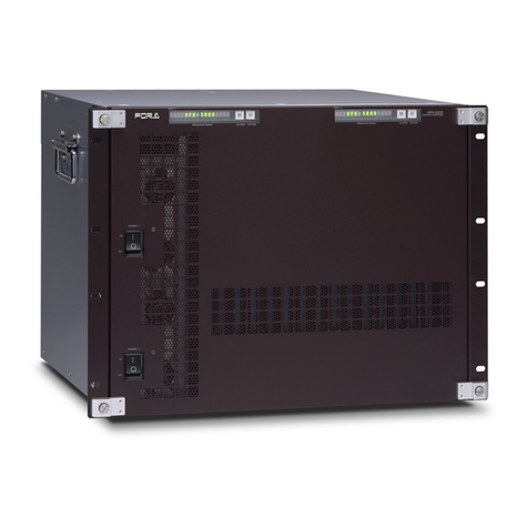
FOR-A MFR-4000 User manual

MFR-4000
Multi Format Routing Switcher
MFR-GPI
MFR-TALM
2nd Edition - Rev. 1
OPERATION
MANUAL

2
Edition Revision History
Edit.
Rev.
Date
Description
Section/Page
1
-
2013/08/13
First edition
2
-
2017/11/29
Support of SNMP
Support of MFR-2SDIGB/2SDOGB
Sec. 1-2
Secs. 2-1-1,
2-2, 2-3-5,
2-3-6, 5, 8-1-1
2
1
2018/08/29
Corrected Matrix Size Chart
Deleted AC adapters from consumable lists
Weight changed
Sec. 2-1-1
Secs. 11-1-3
11-1-4
Sec. 8-1-1

3
Precautions
Important Safety Warnings
[Power]
Caution
Operate unit only at the specified supply voltage.
Disconnect the power cord via the power plug only. Do not pull on the cable portion.
Stop
Do not place or drop heavy or sharp-edged objects on the power cord. A damaged
cord can cause fire or electrical shock hazards. Regularly check the power cord for
excessive wear or damage to avoid possible fire / electrical hazards.
Caution
Ensure the power cord is firmly plugged into the AC outlet.
[Grounding]
Caution
Ensure the unit is properly grounded at all times to prevent electrical shock.
Hazard
Do not ground the unit to gas lines, units, or fixtures of an explosive or dangerous
nature.
[Operation]
Hazard
Do not operate the unit under hazardous or potentially explosive atmospheric
conditions. Doing so could result in fire, explosion, or other hazardous results.
Hazard
Do not allow liquids, metal pieces, or other foreign materials to enter the unit. Doing so
could result in fire, other hazards, or a unit malfunction.
If a foreign material does enter the unit, turn the power off and immediately disconnect
the power cord. Remove the material and contact an authorized service representative
if damage has occurred.
[Transportation]
Hazard
Handle with care to avoid impact shock during transit, which may cause malfunction.
When you need to transport the unit, use the original or suitable alternative packing
material.

4
[Circuitry Access]
Do not remove covers, panels, casing, or access the circuitry with power applied to the
unit. Turn the power off and disconnect the power cord prior to removal. Internal
servicing / adjustment of unit should only be performed by qualified personnel.
Stop
Do not touch any parts / circuitry with a high heat factor.
Capacitors can retain enough electric charge to cause mild to serious shock, even after
the power has been disconnected. Capacitors associated with the power supply are
especially hazardous.
Hazard
Unit should not be operated or stored with cover, panels, and / or casing removed.
Operating the unit with circuitry exposed could result in electric shock / fire hazards or
a unit malfunction.
[Potential Hazards]
Caution
If abnormal odors or noises are noticed coming from the unit, immediately turn the
power off and disconnect the power cord to avoid potentially hazardous conditions. If
problems similar to the above occur, contact an authorized service representative
before attempting to operate the unit again.
[Rack Mount Brackets, Ground Terminal, and Rubber Feet]
Caution
To rack-mount or ground the unit, or to install rubber feet, do not use screws or
materials other than those supplied. Doing so may cause damage to the internal
circuits or components of the unit. If you remove the rubber feet that are attached to the
unit, do not reinsert the screws that secure the rubber feet.
[Consumables]
Caution
Consumable items that are used in the unit must be periodically replaced. For further
details on which parts are consumables and when they should be replaced, refer to the
specifications at the end of the Operation Manual. Since the service life of the
consumables varies greatly depending on the environment in which they are used,
such items should be replaced at an early date. For details on replacing consumable
items, contact your dealer.

5
OpenSSL
This product includes software developed by the OpenSSL Project for use in the OpenSSL Toolkit (http://www.openssl.org/)
Freetype
Portions of this software are copyright © 2005 The FreeType Project (www.freetype.org). All rights reserved.
Lighttpd
Copyright © 2004, Jan Kneschke, incremental. All rights reserved.
Redistribution and use in source and binary forms, with or without modification, are permitted provided that the following conditions
are met:
- Redistributions of source code must retain the above copyright notice, this list of conditions and the following disclaimer.
- Redistributions in binary form must reproducethe abovecopyright notice, this list of conditions andthe following disclaimer inthe
documentation and/or other materials provided with the distribution.
- Neither the name of the 'incremental' nor the names of its contributors may be used to endorse or promote products derived from
this software without specific prior written permission.
THIS SOFTWARE IS PROVIDED BY THE COPYRIGHT HOLDERS AND CONTRIBUTORS "AS IS" AND ANY EXPRESS OR
IMPLIED WARRANTIES, INCLUDING, BUT NOT LIMITED TO, THE IMPLIED WARRANTIES OF MERCHANTABILITY AND
FITNESS FOR A PARTICULAR PURPOSE ARE DISCLAIMED. IN NO EVENT SHALL THE COPYRIGHT OWNER OR
CONTRIBUTORS BE LIABLE FOR ANY DIRECT, INDIRECT, INCIDENTAL, SPECIAL, EXEMPLARY, OR CONSEQUENTIAL
DAMAGES (INCLUDING, BUT NOT LIMITED TO, PROCUREMENT OF SUBSTITUTE GOODS ORSERVICES; LOSS OF USE,
DATA, OR PROFITS; OR BUSINESS INTERRUPTION) HOWEVER CAUSED AND ON ANY THEORY OF LIABILITY,
WHETHER IN CONTRACT, STRICT LIABILITY, OR TORT (INCLUDING NEGLIGENCE OR OTHERWISE) ARISING IN ANY
WAY OUT OF THE USE OF THIS SOFTWARE, EVEN IF ADVISED OF THE POSSIBILITY OF SUCH DAMAGE.
WebHostingHub Glyphs
Copyright (C) 2013 WebHostingHub Glyphs (http://www.webhostinghub.com/glyphs/).
This font is licensed under the SIL Open Font License.
Noto Sans CJK JP Medium
Copyright (C) 2014, 2015 Adobe Systems Incorporated (http://www.adobe.com/).
This Font Software is licensed under the SIL Open Font License, Version 1.1.
* All other copyrights are property of their respective owners.

6
Upon Receipt
MFR-4000 units and their accessories are fully inspected and adjusted prior to shipment. Check your
received items against the packing lists below. Check to ensure no damage has occurred during
shipment. If damage has occurred, or items are missing, inform your supplier immediately.
Main Unit
ITEM
QTY
REMARKS
MFR-4000
1
AC Cord
1 set
AC cable and retaining clip
Rack Mount Brackets
1 set
EIA standard type (Attached to unit.)
CD-ROM
1
Operation manual (PDF)
Quick Setup Guide
1
Input / Output Cards
ITEM
QTY
REMARKS
MFR-9SDI12G
1-8
9 SDI-input card
MFR-9SDO12G
1-8
9 SDI-output card
MFR-8SDIEX
1-8
8 SDI-input card
MFR-8SDOEX
1-8
8 SDI-output card
MFR-2SDIGB
1-8
8 SDI-input card (Gearbox 2ch built-in)
MFR-2SDOGB
1-8
8 SDI-input card (Gearbox 2ch built-in)
* The number of installed cards varies depending on the system configuration. See Sec. 2-1-1. “Matrix
Size Chart.”
Option (for MFR-4000)
ITEM
QTY
REMARKS
MFR-CPUA
1
Redundant CPU card
MFR-PSA
1 set
Redundant power supply unit (with AC cord
and AC cord retaining clip.)
MFR-16/40RU
MFR-16RUD
MFR-16/32/64RUW
MFR-18RU/RUA
MFR-39RU/RUA
MFR-16RUTA
1
Remote Control Unit
Interface Expansion Unit
ITEM
QTY
REMARKS
MFR-GPI
1
AC Adaptor *
1
With DC lock plug
AC Cord
1
Rack Mount Brackets
1 set
EIA standard type
LAN Cable (straight)
1
* Depending on date of production, AC adapter is supplied without DC lock plug, but with a DC cable
retaining clip.

7
Tally Manager Unit
ITEM
QTY
REMARKS
MFR-TALM
1
AC Adaptor *
1
With DC lock plug
AC Cord
1
Rack Mount Brackets
(optional)
1 set
Single- or Dual-unit type
EIA standard type
* Depending on date of production, AC adapter is supplied without DC lock plug, but with a DC cable
retaining clip.
Font Conventions
The following conventions are used throughout this manual:
Shaded text (such as ON) indicates parameter values in the menu.
Text enclosed by a square (such as ALARM, MODE) indicates front panel buttons on the
MFR-4000 or Remote Control Units.
References to the MFR Series Web-based Control Software are indicated by [Web-based
Control: XXX page].

8
Table of Contents
1. Prior to Starting...................................................................................................................................10
1-1. Overview ...................................................................................................................................10
1-2. Features....................................................................................................................................10
2. Panel Descriptions..............................................................................................................................11
2-1. MFR-4000 Front Panel..............................................................................................................11
2-1-1. Matrix Size Chart ...............................................................................................................12
2-2. MFR-4000 Rear Panel..............................................................................................................13
2-2-1. Interfaces...........................................................................................................................14
2-3. SDI Input/Output Cards.............................................................................................................16
2-3-1. MFR-9SDI12G...................................................................................................................16
2-3-2. MFR-9SDO12G .................................................................................................................16
2-3-3. MFR-8SDIEX.....................................................................................................................17
2-3-4. MFR-8SDOEX ...................................................................................................................17
2-3-5. MFR-2SDIGB.....................................................................................................................18
2-3-6. MFR-2SDOGB...................................................................................................................19
2-4. MFR-GPI...................................................................................................................................20
2-4-1. Front Panel ........................................................................................................................20
2-4-2. Rear Panel.........................................................................................................................21
2-4-3. Interfaces (MFR-GPI) ........................................................................................................22
2-4-4. Card Switches....................................................................................................................24
2-5. MFR-TALM................................................................................................................................25
2-5-1. Front Panel ........................................................................................................................25
2-5-2. Rear Panel.........................................................................................................................26
3. System Configuration Example..........................................................................................................27
3-1. Basic Configuration...................................................................................................................27
3-2. Configuring an MFR-TALM.......................................................................................................28
4. Menu Display Operation.....................................................................................................................31
4-1. STATUS....................................................................................................................................32
4-1-1. STATUS > INFO................................................................................................................32
4-1-2. STATUS > MFR-LAN.........................................................................................................33
4-1-3. STATUS > PC-LAN ...........................................................................................................33
4-1-4. STATUS > SLOT ...............................................................................................................33
4-1-5. STATUS > POWER...........................................................................................................34
4-1-6. STATUS > TEMPERATURE .............................................................................................34
4-1-7. STATUS > FAN .................................................................................................................35
4-1-8. STATUS > VERSION ........................................................................................................35
4-1-9. STATUS > ALARM ............................................................................................................35
4-2. SETTING...................................................................................................................................36
4-2-1. Swapping Active CPU........................................................................................................36
4-2-2. Turning ON/OFF an Input/ Output Card ............................................................................36
4-2-3. Changing Power Supply 2 Installation Status....................................................................37
4-2-4. Changing Menu Display Settings.......................................................................................38
5. Gearbox Feature (MFR-2SDIGB / 2SDOGB).....................................................................................39
5-1. MFR-2SDIGB / 2SDOGB Cards ...............................................................................................39
5-2. Available Conversions...............................................................................................................40
5-3. Conversion Settings..................................................................................................................40
5-3-1. Converting 3G SQD input to 2SI (MFR-2SDIGB)..............................................................40
5-3-2. Converting 2SI to SQD Output (MFR-2SDOGB)...............................................................41
5-3-3. Converting 12G-SDI Input to 3G-SDI 2SI (MFR-2SDIGB)................................................42
5-3-4. Converting 3G-SDI SQD to 12G-SDI Output (MFR-2SDOGB).........................................42
6. Serial / LAN Command Control..........................................................................................................43

9
6-1. Serial Interface..........................................................................................................................43
6-2. LAN Interface............................................................................................................................43
6-3. Control Commands...................................................................................................................44
6-3-1. Command Responses (Commands 1-6)...........................................................................45
6-3-2. Receiving Responses (Commands 1-6)............................................................................46
6-3-3. Channel Name Request Commands (7) ...........................................................................49
6-3-4. CPU Status Request Command (8)...................................................................................53
6-3-5. Destination Lock Status Request Command (9)................................................................54
6-3-6. Channel Name Import Commands (10).............................................................................55
7. Troubleshooting..................................................................................................................................56
8. Specifications and Dimensions ..........................................................................................................57
8-1. Unit Specifications.....................................................................................................................57
8-1-1. MFR-4000..........................................................................................................................57
8-1-2. MFR-GPI............................................................................................................................59
8-1-3. MFR-TALM ........................................................................................................................59
8-2. External Dimensions.................................................................................................................60
8-2-1. MFR-4000..........................................................................................................................60
8-2-2. MFR-GPI............................................................................................................................61
8-2-3. MFR-TALM ........................................................................................................................62
Appendix 1. I/ O Card Installation / Replacement ..................................................................................63
1-1. How to Install a New Card.........................................................................................................63
1-2. How to Replace a Card.............................................................................................................64
Appendix 2. Installation/ Replacement of MFR-CPUA (Option) ..................................................65
2-1. How to Install a New MFR-CPUA.............................................................................................65
2-2. How to Replace a CPU1 Card ..................................................................................................66
Appendix 3. Installation/ Replacement of...............................................................................................67
MFR-PSA (Option) .................................................................................................................................67
3-1. How to Install a New MFR-PSA................................................................................................67
3-2. How to Replace an MFR-PSA ..................................................................................................68
Appendix 4. Replacing the Menu Display...............................................................................................69

10
1. Prior to Starting
1-1. Overview
The MFR-4000 is a multi-format routing switcher that supports 12G-SDI, 3G-SDI, HD-SDI, SD-SDI,
and ASI signals. Inside the 6U case a matrix of up to 72 inputs/ 72 outputs can be configured. It
supports various functions such as the capability of linking multiple units, tally connections with
peripheral devices, and automatic source name tracking, to allow the units to be the core product in
small to medium size systems.
1-2. Features
Support for 12G-SDI, 3G-SDI, HD-SDI, and ASI signals with automatic signal recognition that
enables operation without concern for the type of signal. Changing the input/output card
enables support for SD-SDI signals.
One routing switcher can be virtually partitioned to build any theoretical hierarchy, which
creates possibilities for use in various operating forms.
Various crosspoint control functions such as Salvo, Take, Link, Level operation, and Chop
Tally linking with FOR-A’s video switchers (HANABI Series) and multi viewers. Source name
displays on video switchers and multi viewers can be switched in conjunction with switching
controlled in the main unit. MFR routers support TSL and Harris protocol, enabling linkage to
other companies' products.
Built-in webserver for remote control through a web browser
SNMP support enabling SNMP monitoring system configuration
Status monitoring for power supply, fan, CPU, SDI input/output, etc.
CPU board redundancy allowing monitoring of primary CPU board operation via the
secondary board. Real time and smooth switching over to secondary board without down time
in case of malfunctions, as well as stable remote control operation supported by network
redundancy
Power unit redundancy for stable power supply against power unit failure or power supply
troubles
Main unit front display of settings and alarms enabling the main unit to take over operation in
the event a remote environment goes down.
Matrix partition and level setting capabilities support a flexible control environment (maximum
of 128 units total including main unit)
Remote control panel connectivity for configuring a huge control panel
Interface expansion unit (MFR-GPI) for additional 128 (32 x 4) GPI/O and 4 serial ports (9-pin
D-sub, male)
MFR-TALM Tally Manager Unit is designed specifically to manage tally and signal name data
in the MFR system and exchange of this data with external devices such as video switchers,
multiviewers, etc. The unit performs the task of tally data computation, ordinarily undertaken
by the MFR main unit, to accelerate the task.
Allows conversions between 12G-SDI and Quad Link 3G-SDI signals, and between 2SI and
SQD, by installing optional MFR-2SDIGB and MFR-2SDOGB (Gearbox feature built-in) cards.

11
2. Panel Descriptions
2-1. MFR-4000 Front Panel
MFR
POWER CPU1 CPU2
POWER 1
ON
OFF
POWER 2
ON
OFF
ROUTINGSWITCHER
MFR-4000
No.
Name
Description
A
POWER1
Switch used to turn unit power ON / OFF.
B
POWER2
Switch used to power ON / OFF the optional power supply.
C
Status
Indicators
POWER
Lit green
Power is supplied to the unit.
Unlit
No power is supplied to the unit. Or power supply
unit is not installed.
Lit red
A failure has occurred. Turn off the power supply unit
immediately and consult your reseller.
CPU1
Lit green
CPU1 card (standard equipment/ Primary CPU) is
active.
Unlit
CPU1 card (standard equipment/ Primary CPU) is
inactive.
CPU2
Lit green
CPU2 card (optional equipment/ Secondary CPU) is
active.
Unlit
CPU2 card (optional equipment/ Secondary CPU) is
inactive.
D
Menu Display
Displays menu. See Sec. 4. “Menu Display Operation” for
details.

12
2-1-1. Matrix Size Chart
Standard SDI Signal Routing
Matrix size varies depending on the number of installed MFR-9SDI12G and MFR-9SDO12G
cards as shown below. (72 x 72 to 9 x 9)
Number of cards: MFR-9SDO12G
8
7
6
5
4
3
2
1
Number of
cards:
MFR-9SDI12G
8
72 x 72
72 x 63
72 x 54
72 x 45
72 x 36
72 x 27
72 x 18
72 x 9
7
63 x 72
63 x 63
63 x 54
63 x 45
63 x 36
63 x 27
63 x 18
63 x 9
6
54 x 72
54 x 63
54 x 54
54 x 45
54 x 36
54 x 27
54 x 18
54 x 9
5
45 x 72
45 x 63
45 x 54
45 x 45
45 x 36
45 x 27
45 x 18
45 x 9
4
36 x 72
36 x 63
36 x 54
36 x 45
36 x 36
36 x 27
36 x 18
36 x 9
3
27 x 72
27 x 63
27 x 54
27 x 45
27 x 36
27 x 27
27 x 18
27 x 9
2
18 x 72
18 x 63
18 x 54
18 x 45
18 x 36
18 x 27
18 x 18
18 x 9
1
9 x 72
9 x 63
9 x 54
9 x 45
9 x 36
9 x 27
9 x 18
9 x 9
Matrix size varies depending on the number of installed MFR-8SDIEX, MFR-8SDOEX,
MFR-2SDIGB and MFR-2SDOGB cards as shown below. (64 x 64 to 8 x 8)
Number of cards: MFR-8SDOEX/MFR-2SDOGB
8
7
6
5
4
3
2
1
Number of
cards:
MFR-8SDIEX
/MFR-2SDIGB
8
64 x 64
64 x 56
64 x 48
64 x 40
64 x 32
64 x 24
64 x 16
64 x 8
7
56 x 64
56 x 56
56 x 48
56 x 40
56 x 32
56 x 24
56 x 16
56 x 8
6
48 x 64
48 x 56
48 x 48
48 x 40
48 x 32
48 x 24
48 x 16
48 x 8
5
40 x 64
40 x 56
40 x 48
40 x 40
40 x 32
40 x 24
40 x 16
40 x 8
4
32 x 64
32 x 56
32 x 48
32 x 40
32 x 32
32 x 24
32 x 16
32 x 8
3
24 x 64
24 x 56
24 x 48
24 x 40
24 x 32
24 x 24
24 x 16
24 x 8
2
16 x 64
16 x 56
16 x 48
16 x 40
16 x 32
16 x 24
16 x 16
16 x 8
1
8 x 64
8 x 56
8 x 48
8 x 40
8 x 32
8 x 24
8 x 16
8 x 8

13
2-2. MFR-4000 Rear Panel
CPU2
MFR-LAN PC-LAN
PC-LANMFR-LAN
CPU1
ALARM
SERIAL
232C 422
REF IN
AC100-240V50/60HzIN
AC100-240V50/60HzIN
12
OUTPUT
1 2 3 4 5 6 7 8
INPUT
1 2 3 4 5 6 7 8
1
2
3
4
5
6
7
8
9
1
2
3
4
5
6
7
8
9
1
2
3
4
5
6
7
8
9
1
2
3
4
5
6
7
8
9
1
2
3
4
5
6
7
8
9
1
2
3
4
5
6
7
8
9
1
2
3
4
5
6
7
8
9
1
2
3
4
5
6
7
8
9
111 11111
2 2 2 2 2 2 2 2
33333333
4 4 4 4 4 4 4 4
55555555
6 6 6 6 6 6 6 6
77777777
8 8 8 8 8 8 8 8
99999999
*The above figure shows an MFR-4000 with MFR-9SDI12G and MFR-9SDO12G cards installed.
No.
Name
Description
A
MFR-LAN
(CPU1 / CPU2)
Ethernet ports for connection to MFR Remote Control Units and
MFR-GPI (10/100BASE-TX, RJ-45)
B
PC-LAN
(CPU1 / CPU2)
Ethernet ports for connection to PC or other external unit
(10/100/1000BASE-T, RJ-45)
C
SERIAL
Used for control via a serial interface. RS-232C or RS-422 selectable.
►See Sec. 2-2-1. “Interfaces.”
D
ALARM
Used for alarm output
►See Sec. 2-2-1. “Interfaces.”
E
REF IN1, 2
Used to input reference signals (BB or Tri-level sync signal)
(with loop-through. Terminate with 75Ω terminator, if unused.)
F
AC IN1
Used to connect Power Supply Unit 1 (standard equipment) to an AC
power source
G
AC IN2
Used to connect Power Supply Unit 2 (optional) to an AC power
source
H
INPUT 1-8
MFR-9SDI12G/8SDIEX/2SDIGB: Used to input digital component
video signals
I
OUTPUT 1-8
MFR-9SDO12G/8SDOEX/2SDOGB: Used to output digital
component video signals
J
Ground Terminal
Used to ground the unit to protect operators against static electricity
and/ or electrical shock.
IMPORTANT
All 4 MFR-LAN and PC-LAN connectors (2 each) must be connected to their respective devices
to enable CPU redundancy. The LAN connections for MFR Series devices must be separated
from the network segment of other devices.
Cooling fan location
CPU2
MFR-LAN PC-LAN
PC-LANMFR-LAN
CPU1
ALARM
SERIAL
232C 422
REF IN
AC100-240V50/60HzIN
AC100-240V50/60HzIN
12
OUTPUT
1 2 3 4 5 6 7 8
INPUT
1 2 3 4 5 6 7 8
1
2
3
4
5
6
7
8
9
1
2
3
4
5
6
7
8
9
1
2
3
4
5
6
7
8
9
1
2
3
4
5
6
7
8
9
1
2
3
4
5
6
7
8
9
1
2
3
4
5
6
7
8
9
1
2
3
4
5
6
7
8
9
1
2
3
4
5
6
7
8
9
111 11111
2 2 2 2 2 2 2 2
33333333
4 4 4 4 4 4 4 4
55555555
6 6 6 6 6 6 6 6
77777777
8 8 8 8 8 8 8 8
99999999

14
2-2-1. Interfaces
SERIAL Connector (9-pin D-sub, male)
Select RS-232C or RS-422 using the slide switch
on top of the connector.
RS-232C Connector Pin Assignments
Pin No.
Signal Name
Description
1
NC
Not used
2
RxD
Received Data
3
TxD
Transmitted Data
4
DTR
Data Terminal Ready
5
SG
Signal Ground
6
DSR
Data Set Ready
7
RTS
Request To Send
8
CTS
Clear To Send
9
NC
Not used
The maximum cable length is 10 m.
DTR/DSR and RTS/CTS are internally connected respectively.
RS-422 Connector Pin Assignments (Factory default settings)
Pin No.
Signal Name
Description
1
FG
Frame ground
2
T-
Transmit data (-)
3
R+
Receive data (+)
4
SG
Signal Ground
5
NC
Not used
6
SG
Signal Ground
7
T+
Transmit data (+)
8
R-
Receive data (-)
9
FG
Frame Ground
The maximum cable length is 100 m.

15
ALARM Connector (9-pin D-sub, female)
Alarm 1 Out:
Normal operation:
Pins 1 and 6 are open.
Malfunction or power-off:
Pins 1 and 6 are closed.
Alarm 2 Out:
Normal operation:
Pins 2 and 7 are open.
Malfunction or power-off:
Pins 2 and 7 are closed.
ALARM Connector Pin Assignments
Pin No.
Signal Name
Description
1
ALARM1 OUT
Alarm 1 output (Default setting: Fan)
2
ALARM2 OUT
Alarm 2 output (Default setting: Power)
3
NC
Not used
4
NC
Not used
5
NC
Not used
6
ALARM 1 COMMON
Alarm 1 output, common
7
ALARM 2 COMMON
Alarm 2 output, common
8
GND
Signal Ground
9
GND
Signal Ground
The following items can be set for ALARM1OUT and ALARM2 OUT. Alarms can be assigned
in Web-based Control.
Available alarm signals
Fan (including power unit cooling fans)
Power
Secondary CPU error
CPU Changeover (issued when activated to change over to secondary CPU operation)
Crosspoint Error

16
2-3. SDI Input/Output Cards
2-3-1. MFR-9SDI12G
The MFR-9SDI12G is an SDI input card and can accept 9 total of 12G/3G/HD-SDI and ASI
signals.
Up to 8cards can be installed into Slot No. 01 to 08.
►See Sec. 2-1-1. “Matrix Size Chart.”
1
2
3
4
5
6
7
8
9
BNC x 9 inputs (12G/3G/HD-SDI or ASI signal auto-detection)
Set up input signals in the Web-based Control Software as shown below.
Source Name
Open the [Web-based Control: ROUTER SYSTEM SETTINGS - Source Name page].
This page allows you to change source names displayed on Remote Controllers or other
devices.
Source Assignment
Open the [Web-based Control: ROUTER SYSTEM SETTINGS - Source Assignment page].
This page allows you to assign physical inputs to logical input channels.
2-3-2. MFR-9SDO12G
The MFR-9SDO12G is an SDI output card and can accept 9 total of 12G/3G/HD-SDI and ASI
signals.
Up to 8cards can be installed into Slot No. 09 to 16.
►See Sec. 2-1-1. “Matrix Size Chart.”
1
2
3
4
5
6
7
8
9
BNC x 9 outputs (12G/3G/HD-SDI or ASI signal depending on crosspoint selection)
Set up output signals in the Web-based Control Software as shown below.
Destination Name
Open the [Web-based Control: ROUTER SYSTEM SETTINGS - Destination Name page].
This page allows you to change destination names displayed on Remote Controllers or other
devices.
Destination Assignment
Open the [Web-based Control: ROUTER SYSTEM SETTINGS - Destination Assignment
page].
This page allows you to assign physical outputs to logical output channels.

17
2-3-3. MFR-8SDIEX
The MFR-8SDIEX is an SDI input card and can accept 8 total of 3G/HD/SD-SDI signals.
Up to 8cards can be installed into Slot No. 01 to 08.
►See Sec. 2-1-1. “Matrix Size Chart.”
9
8
7
6
5
4
3
2
BNC x 8 inputs (3G/HD/SD-SDI)
Set up input signals in the Web-based Control Software as shown below.
Source Name
Open the [Web-based Control: ROUTER SYSTEM SETTINGS - Source Name page].
This page allows you to change source names displayed on Remote Controllers or other
devices.
Source Assignment
Open the [Web-based Control: ROUTER SYSTEM SETTINGS - Source Assignment page].
This page allows you to assign physical inputs to logical input channels.
2-3-4. MFR-8SDOEX
The MFR-8SDOEX is an SDI output card and can accept 8 total of 3G/HD/SD-SDI signals.
Up to 8cards can be installed into Slot No. 09 to 16.
►See Sec. 2-1-1. “Matrix Size Chart.”
9
8
7
6
5
4
3
2
BNC x 8 outputs (3G/HD/SD-SDI signal depending on crosspoint selection)
Destination Name
Open the [Web-based Control: ROUTER SYSTEM SETTINGS - Destination Name page].
This page allows you to change destination names displayed on Remote Controllers or other
devices.
Destination Assignment
Open the [Web-based Control: ROUTER SYSTEM SETTINGS - Destination Assignment
page].
This page allows you to assign physical outputs to logical output channels.

18
2-3-5. MFR-2SDIGB
The MFR-2SDIGB is a 12G/3G-SDI input card. Its Gearbox function enables conversion
between 12G-SDI and Quad Link 3G-SDI signals and conversion between 2SI and SQD
signals.
Maximum of 8 cards can be installed into slot Nos.01-08.
►See Sec. 2-1-1. “Matrix Size Chart.”
The following listed SDI signals can be input.
12G-SDI: Max. 2 inputs (BNC 1A, 2A)
3G-SDI: Max. 8 inputs
►See Sec. 2-1-1. “Matrix Size Chart.”
1A
1B
1C
1D
2A
2B
2C
2D
12G / 3G-SDI12G / 3G-SDI
BNC x 8 inputs (12G/3G-SDI)
Set up input signals in the Web-based Control Software as shown below.
Gearbox settings
Open the [Web-based Control: (Main Unit Settings)-Gearbox Settings page].
This page allows you to specify input/ output signals to Gearbox, reference signal and delay.
Source Name
Open the [Web-based Control: (Router System Settings)-Source Name page.].
This page allows you to change displayed source names on Remote Controllers or other
devices.
Source Assignment
Open the [Web-based Control: (Router System Settings)-Source Assignment page].
This page allows you to assign physical inputs to logical input channels.

19
2-3-6. MFR-2SDOGB
The MFR-2SDOGB is a 12G/3G-SDI output card. Its Gearbox function enables conversion
between 12G-SDI and Quad Link 3G-SDI signals, and between 2SI and SQD signals.
Max. 8 cards can be installed into slot Nos.09-16.
►See Sec. 2-1-1. “Matrix Size Chart.”
The following listed SDI signals can be input.
12G-SDI: Max. 2 outputs (BNC 1A, 2A)
3G-SDI: Max. 8 outputs
►See Sec. 2-1-1. “Matrix Size Chart.”
1A
1B
1C
1D
2A
2B
2C
2D
12G / 3G-SDI12G / 3G-SDI
BNC x 8 Outputs (12G/3G-SDI)
Set up output signals in the Web-based Control Software as shown below.
Gearbox settings
Open the [Web-based Control: (Main Unit Settings)-Gearbox Settings page].
This page allows you to specify input/ output signals to Gearbox, reference signal and delay.
Destination Name
Open the [Web-based Control: (Router System Settings)-Destination Name page.].
This page allows you to change destination names displayed on Remote Controllers or other
devices.
Source Assignment
Open the [Web-based Control: (Router System Settings)-Destination Assignment page].
This page allows you to assign physical outputs to logical output channels.

20
2-4. MFR-GPI
2-4-1. Front Panel
No.
Item
Description
A
POWER
Displays the power status.
►See the table below for details on indications.
B
BUSY
Displays the flash memory writing status of backup settings.
►See the table below for details on indications.
C
GPI
When the GPI function is assigned using Web-based Control, the
LED lights green. The LED remains unlit when there is no
assignment.
D
SERIAL1 - 4
When a serial port is assigned using Web-based Control, the LED
lights green. The LED remains unlit when there is no assignment.
E
RESET
Used to re-initialize the GPI unit.
Color indications on the MFR-GPI front panel
LED Color
LED
Green
Red
Orange
POWER
Normal
Power alarm
BUSY
Normal processing
Writing to flash
memory
* POWER LED lights red if the unit is turned on but is unconnected to a network.
IMPORTANT
After finishing settings, do not power OFF the unit while BUSY LED is lit orange, since the
system is writing to Flash memory. (approx. 2 minutes max.)
POWER BUSY GPI 1 2 3 4
SERIAL RESET
MFR-GPI
GPIUNIT
A
B
D
E
C
Other manuals for MFR-4000
1
Table of contents
Other FOR-A Network Router manuals