for Living 085-1522-0 User manual

1
Flame Patio Heater
Model No. 085-1522-0
Instruction Manual
Toll-free: 1-877-483-6759
IMPORTANT: Please read this manual carefully before beginning assembly of this product.
Keep this manual for future reference.
2
!WARNING: For outdoor use only.
Important Safety Instructions 2
! DANGER
If you smell gas:
1. Shut off gas to the appliance.
2. Extinguish any open flame.
3. If odour continues, keep away from the appliance and immediately call your
gas supplier or fire department.
Failure to follow these instructions could result in fire, explosion or burn
hazard, which could cause property damage, personal injury or death.
Read the installation, operating and maintenance instructions thoroughly
before installing or servicing this equipment.
WARNING
Do not store or use gasoline or other flammable vapours and liquids
in the vicinity of this or any other appliance.
An LP-cylinder not connected for use must not be stored in the
vicinity of this or any other appliance.
WARNING : Improper installation,
adjustment,alteration,service or
maintenance can cause property
damage,injury or death.Read the
installation,operating and maintenance
instructions thoroughly before installing
or servicing this equipment.
CARBON MONOXIDE HAZARD
This appliance can produce carbon monoxide
which has no odor.
Using it in an enclosed space can kill you.
Never use this appliance in an enclosed space
such as a camper,tent,car or home.

3
Important Safety Instructions
3 Model No. 085-1522-0
This instruction manual contains important information necessary for the
proper assembly and safe use of the appliance.
Read and follow all warnings and instructions before assembling and
using the appliance.
Follow all warnings and instructions when using the appliance.
Keep this manual for future reference.
Note to installer: Leave this Instruction Manual with the consumer after delivery and/or
installation.
Note to customer: Leave this Instruction Manual in a convenient place for future reference.
STOP!
Should you encounter a problem with your new e patio heater, call us
rst!
Question, problems, missing parts? Do not return the product to the store.
We can help: 1-877-483-6759.

4
Product Speci cations 4
Safety Information 5
Exploded View 8
Parts List 10
Assembly Preparation 13
Assembly 14
How to Open the Knob Lid 30
Safety Check 32
Operating Instructions 32
Care and Maintenance 33
Storage 34
Troubleshooting 34
Warranty 35
PRODUCT SPECIFICATIONS
ASCnoitacifitreC
2” (2.1 m)8llarevOthgieH
18 1/8" (46 cm)retemaiDrotcelfeR
RH/UTB000,04OutputtaeHdetaR
PL-enaporPleuF
rednilycsaG- PLb (9 kg)l02ylppuSsaG
C.W11" (28 cm)erusserPdlofinaM
0.08" (2.0 mm)e (diameter)ziSrotcejnI
hctiwStliT&elpuocomrehTserutaeFytefaS
GasSupply Pressure Max150 PSI, Min5 PSI
Produc
Table Of Contents
4
Product Specifications

5
SAFETY INFORMATION
If these instructions are ignored, there is a possibility of a hazardous fire or explosion which
could result in physical injury or property damage! It is your responsibility to assemble,
operate and maintain your flame patio heater inasafe manner.
Please read and understand this entire manual before attempting to assemble, operate or install
the product.
WARNINGS:
1. The installation must conform with local codes or, in the absence of local codes, with the
2. Minimum clearance to the combustible materials is 59" (150 cm).
3. Perform a leak test with a soapy solution:
(a) To check gas connections.
(b) After connecting a new cylinder.
(c) Upon re-assembly after disassembly.
Please refer to the leak test procedure indicated in this instruction manual on page 32.
Replace the hose assembly prior to the appliance being put into operation if there is
evidence of excessive abrasion or wear, or if the hose is damaged. The pressure regulator
and hose assembly supplied with the appliance must be used. The replacement hose
assembly/regulator must be that specified by the manufacturer.
4. If you don’t feel the heater is on a stable surface, use a ground screw to fix the base of the
heater on the surface where the heater is installed. Fix the base on an incline no wider than
15°.
5. Place the propane hose with regulator assembly out of pathways where people may trip
over it or in areas where the hose will not be subjected to accidental damage.
6. This heater is equipped with a battery-operated ignition device; please refer to the
assembly instructions on page 32.
7. Materials or items when stored under the heater will be subjected to intense heat and
could be seriously damaged.
8. Clothing or other flammable materials should not be hung on the heater, or placed on,
under or near the heater.
9. Children and adults should be alerted to the hazards of high surface temperatures and
should stay away to avoid burns or clothing ignition.
10. Young children should be carefully supervised when they are in the area of the heater.
11. Any guard or other protective device removed for servicing the heater must be replaced
Safety Information
5
5
Model No. 085-1522-0
National Fuel Gas Code, ANSI Z223.1/NFPA 54, Natural Gas and Propane Installation Code,
CSA B149.1, or Propane Storage and Handling Code, B149.2.

6
prior to operating the heater.
12. Installation and repair should be done by a qualified service person; the heater
should be inspected before use and at least annually by a qualified service person.
13. More frequent cleaning may be required as necessary. It is imperative that the control
compartment, burners and circulating air passageways of the heater be kept clean.
14. Keep the appliance area clear and free from combustible materials, gasoline and other
flammable vapours and liquids.
15. Do not obstruct the flow of combustion and ventilation air.
16. Keep the ventilation opening(s) of the cylinder enclosure free and clear of debris. Use
this appliance in a well-ventilated space only. Do not use it in a building, garage, or any other
enclosed area.
Use this appliance in outdoor areas described below:
(a) With walls on all sides, but at least one permanent opening at ground level and no
overhead cover.
(b) Within a partial enclosure that includes overhead cover and no more than two walls.
These walls may be parallel, or at right angles to each other.
(c) Within a partial enclosure that includes overhead cover and no more than two walls.
The following shall apply:
(i) One wall that is equivalent to at least 25% of the total wall area is completely
open.
(ii) 30% or more in total of the remaining wall area is open and unrestricted.
17. The LP-gas supply cylinder to be used must be:
(a) Constructed and marked in accordance with the Specifications for LP-gas cylinders of the
U.S. Department of Transportation (D.O.T) or the National standard of Canada, CAN/CSA-B339,
as applicable;
(b) Provided with a listed overfilling prevention device; and
(c) Provided with a cylinder connection device compatible with the connection for the
appliance.
18. Disconnect the cylinder when the appliance is not in use.
19. Storage of an appliance indoors is permissible only if the cylinder is disconnected and
removed from the appliance.
20. Store the cylinder outdoors in a well-ventilated area (not in a building, garage, or other
enclosed area) out of the reach of children.
21. The cylinder used must include a collar to protect the cylinder valve.
22. Do not store a spare LP-gas cylinder under or near this appliance;
23. Never fill the cylinder beyond 80% full;
24. Place the dust cap tightly on the cylinder valve outlet whenever the cylinder is not in use.
Install only the type of dust cap on the cylinder valve that is provided with the cylinder valve.
Other types of caps or plugs may result in a propane leak.
Safet
y
Information
6

7
25. Inspect the visible portion of the hose before each use of the appliance.
27. Every part of the heater must be secure against displacement and must be constructed
to maintain a fixed relationship between essential parts under normal and reasonable
conditions of handling and usage. Parts not permanently secured must be designed so they
cannot be incorrectly assembled and cannot be improperly located or misaligned in
removing or replacing during cleaning or other servicing.
28. CALIFORNIA PROPOSITION 65 WARNING:
(a) Combustion by-products produced when using this product contain chemicals known to
the State of California to cause cancer and birth defects or other reproductive harm.
(b) Handling the brass material on this product exposes you to lead, a chemical known to
the State of California to cause cancer and birth defects or other reproductive harm. Wash
hands after handling.
(c) This product contains chemicals, including lead and lead compounds, known by the State
of California to cause cancer, reproductive harm, or other birth defects.
(d) Wash your hands after using this product.
Safety Information
7
Model No. 085-1522-0
WARNING!
R
ET
A
I
N
FOR FUTURE
REFERENCE,
AND READ
C
A
R
EF
U
LL
Y!
26. More frequent cleaning may be required as necessary. It is imperative that the control
compartment, burners and circulating air passageways of the heater be kept clean.
8
1
2
6
3
23
17
7
11
8
10
5
4
24
9
16
18
15
14
13
12
22
2
1
2
B
0
19
26
25
8
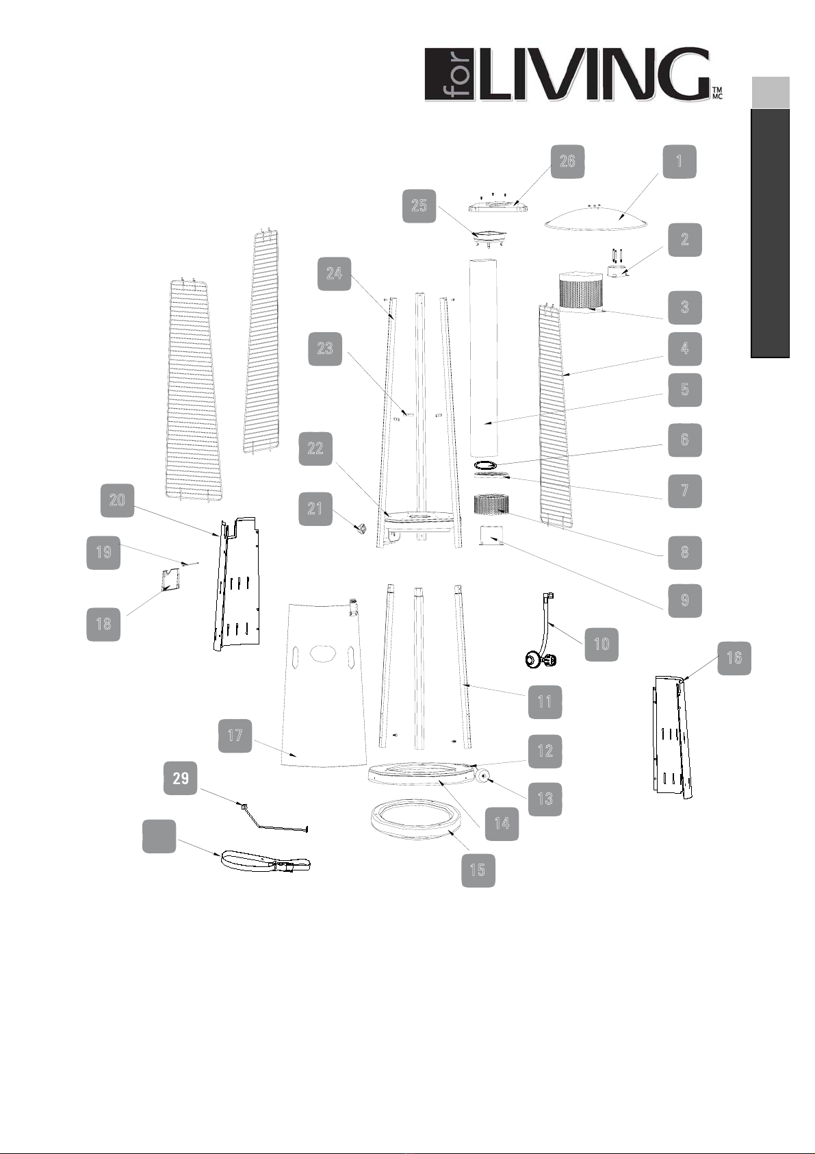
Exploded View
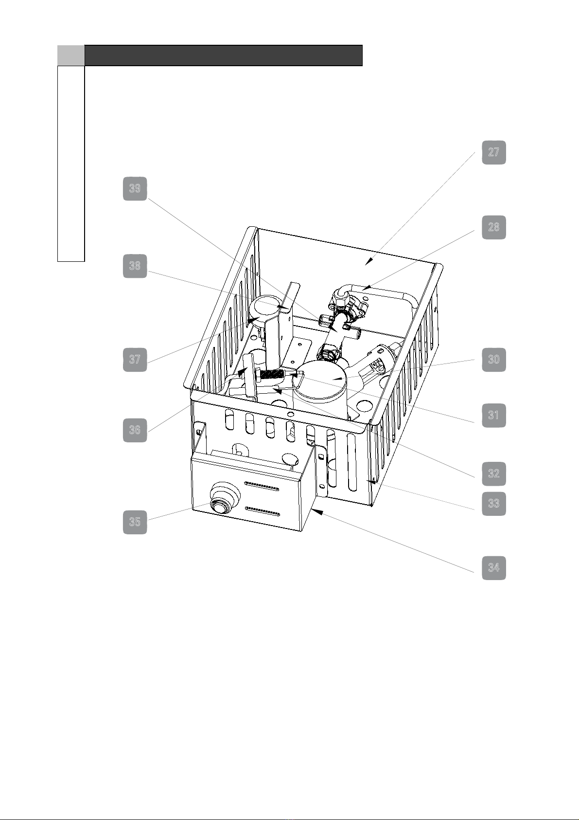
9
32
31
30
29
28
27
Exploded View
9
Model No. 085-1522-0
39
38
37
36
35
34
33

10
10
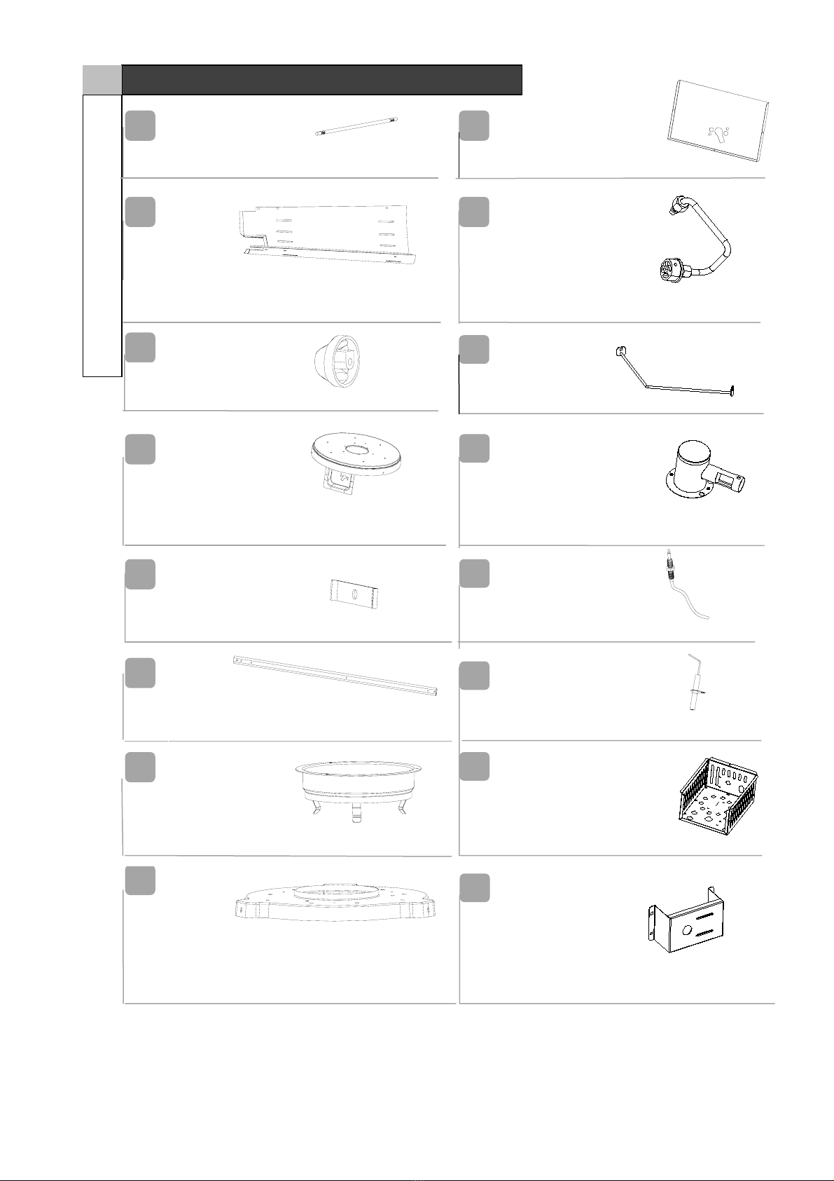
Parts List
1
2
3
4
5
6
Small Round Cover Assembly - 1
Reector - 1
Round Cover Assembl
y
- 1
Protecting Guard - 3
7
Glass Tube - 1
8
Silica Gel Ring - 1
Outside Cover - 1
11
Lower Holder For Glass Tube - 1
12
13
14
15
18
16
17
Wind Shield - 1
Regulator - 1
Lower Support Member - 3
Wheel Bracket - 1
Wheel - 2
Base Assembly - 1
9
10
Wei
g
ht Plate - 1
Columnar Body 1 - 1
Door Assembly - 1
Knob Cover - 1
11
Columnar Body 2 Assembly - 1
Parts List
11 Model No. 085-1522-0
Rotation Shaft For Knob Cover - 1
Knob - 1
1
9
20
21
22
23
24
Plate Cover Assembl
y
- 1
Hooks - 3
Upper Support Member - 3
25
Upper Holder For Glass Tube - 1
26
Upper Plate - 1
27
Clapboard 1 For Valve - 1
28
Gas Pipe Assembly - 1
29
30
31
32
33
34
Separator
Burner Assembly - 1
Thermocouple - 1
Ignition Pin - 1
Clapboard 2 For Valve - 1
Installation Plate For Electronic Igniter - 1

12
12
Parts List
Electronic I
g
nition - 1
35
36
37
38
39
A
Ignition Pin Holder - 1
Tilt Over Switch - 1
Support Brack etFo rTilt Switch - 1
B
Valve - 1
C
M5 Dome Nut - 3
Cylinder Belt - 1
F
Ф5 Washer - 1
G
H
I
Battery - 1
M6x10 Bolt - 3
ST3.5x8 - 5
ST4.2x10 - 3
M4x10 Screw - 13
r - 3
D
E

13
DO NOT RETURN YOUR PRODUCT TO THE STORE. CALL
US FIRST!
1-877-483-6759
If you have questions regarding your product, require warranty assistance,
or have damaged or missing parts, please call our customer service toll-free
helpline.
Contact us for assistance:we’re here to help.
IMPORTANT: Please read and understand this manual before any assembly. Before
beginning assembly of product, make sure all parts are present. Compare parts with
packaging contents list. If any part is missing, or if you have questions, contact the
service centre at 1-877-483-6759 (toll free).
Place all parts from the box in a cleared area and position them on the floor in front of
you. Remove all packing materials and place them back into the box. Do not dispose
of the packing materials until assembly is complete. Reach step carefully before
beginning any assembly and make sure you understand each step. If you are missing
a part, please call our toll-free number for assistance:1-877-483-6759.
Needed for assembly (not included):
Adjustable Open Wrench Magnetic head Cross-head Screwdriver 2 people
Estimated Assembly Time: 40 minutes
13 Model No. 085-1522-0
Assembly Preparation
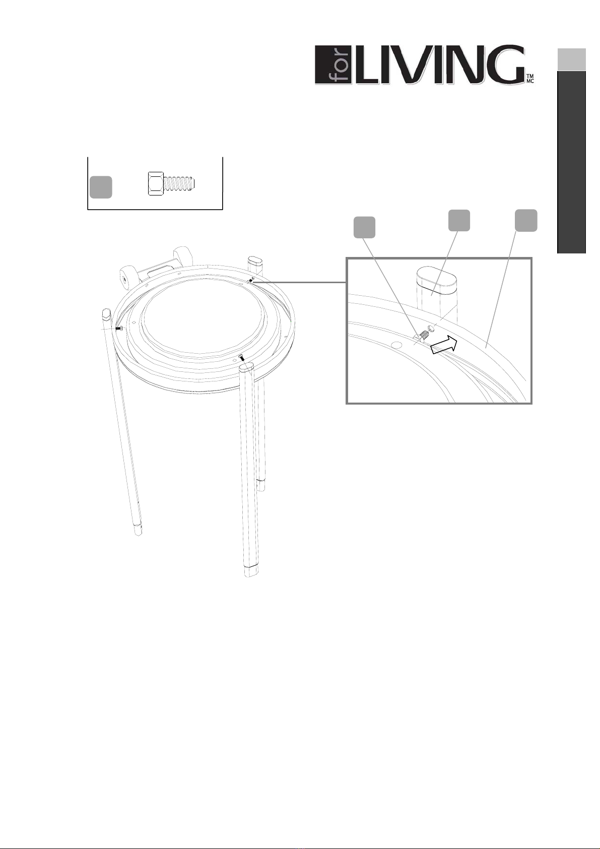
14
Step
1
Requires
14, 11, E
Fix the bottom base (14) and 3 pcs lower support members (11) with 3 pcs M6x10 bolt
(E).
14
Assembly
E
11
11
E14

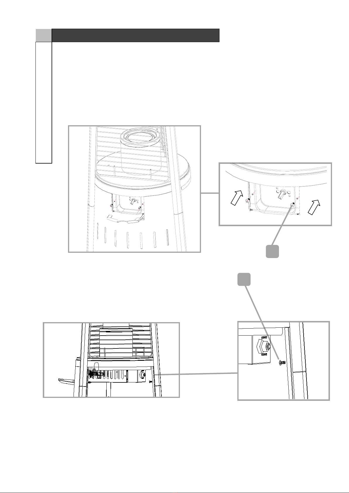
15
Step 2
Requires 16
, 20, 29, H
Assemble 1pc columnar body 1 (16) and 1pc columnar body 2 assembly (20) with 6 pcs
M4x10Screw (H) . Attach the separator (29) to two
M4x10screws, and fasten them.
Step 3 Loosen Upper Plate 26
Loosen 3 pcs M4x10 screw (H) , and then take out upper plate (26).
15 Model No. 085-1522-0
Assembly
16
20
H
29

16
16
Assembly
26
M4 Screw

17
Step 4
Requires Step 2 and Step 3 Assemblies, each 1 pc
Attach the upper part of the heater to the columnar body.
17 Model No. 085-1522-0
Assembly

18
18
Assembly
19
Step 5
Requires 1 pc Step 4 Assemblies, F, H
Screw the upper part and columnar body with 2 pcs ST3.5x8 self-tapping screw (F) and 3
pcs M4x10 screw (H).
19 Model No. 085-1522-0
Assembly
F
H
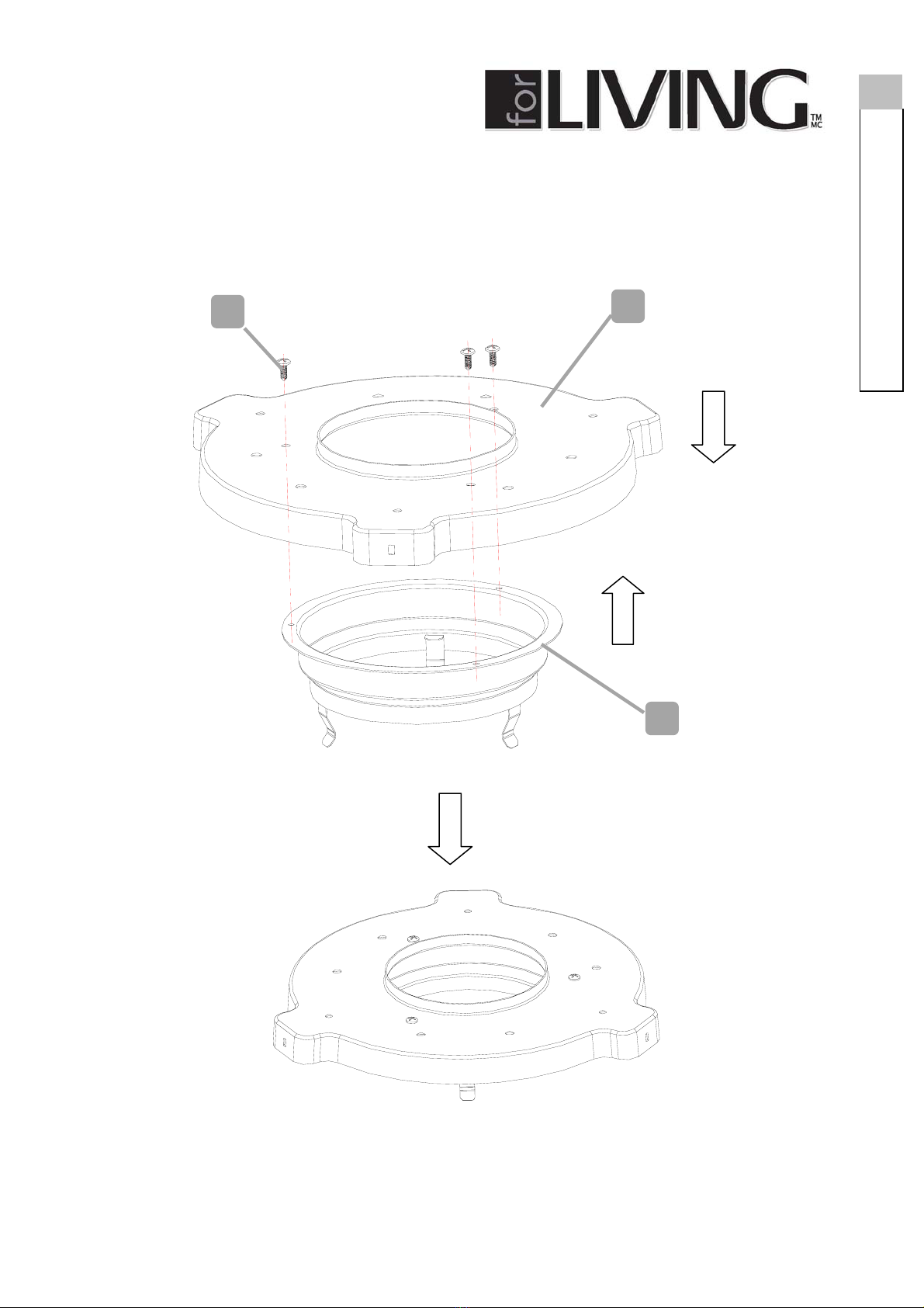
20
Step 6
Requires 25 (1 pc), 26 (1 pc), G (3 pcs)
Attach 1 pc upper plate 26 to 1 pc upper holder for glass tube and fix them with 3 pcs
ST4.2x10 self-tapping screw (G).
20
Assembly
26
25
G
Table of contents
Other for Living Patio Heater manuals

Popular Patio Heater manuals by other brands

EUROM
EUROM Spirit 1500 instruction manual

Flash Furniture
Flash Furniture NAN-FSDC-02-BR-GG owner's manual

EUROM
EUROM PD2100XXL instruction manual

OriPower
OriPower H1207 instruction manual

Sonnenkonig
Sonnenkonig WARMEPILZ ELEKTRO black user manual

Outback
Outback OUT370610/PH200T Assembly and operating instructions


