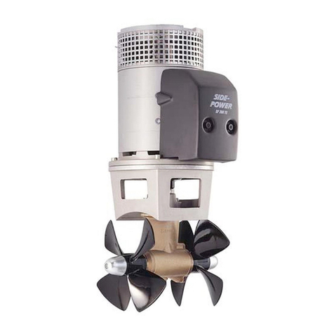
Force 75 User manual

90-826881990 398- 1 -Printed in U.S.A.
FORCE 75/90/120 MODELS
INSTALLATION MANUAL
NOTICE to INSTALLER
After Completing Installation, These Instruc-
tions Should Be Placed with the Product for
the Owner’s Future Use.
75/90/120 Model
This installation manual provides outboard installa-
tion procedure, proper setup and necessary adjust-
ments. PLEASE READ CAREFULLY AND THOR-
OUGHLY BEFORE BEGINNING INSTALLATION.
The remote control connected to your outboard
MUST be equipped with a start-in-gear protection de-
vice. This prevents the engine from starting when the
outboard is in gear.
1998 Mercury Marine
The following are registered trademarks of Brunswick Corpora-
tion: Autoblend, Force, Jet-Prop, Mariner, Merc, MerCathode,
MerCruiser, Mercury, Mercury Marine, Quicksilver, Ride-Guide,
Sport-Jet, and Thruster.
Table of Contents Page
Notice to Installer and Owner 2. . . . . . . . . . . . . . . . .
Selecting Steering Cables and
Remote Control Cables 2. . . . . . . . . . . . . . . . . . . .
Installing Outboard on Transom 2. . . . . . . . . . . . . . .
Determining Recommended
Outboard Mounting Height 2. . . . . . . . . . . . . .
Locating Centerline of Boat Transom 2. . . . . . .
Drilling Outboard Mounting Holes 3. . . . . . . . . .
Lifting Outboard 3. . . . . . . . . . . . . . . . . . . . . . . . .
Securing Outboard to Boat Transom 3. . . . . . . .
Ride Guide Steering Cable/Attaching
Kit Installation 4. . . . . . . . . . . . . . . . . . . . . . . . . . . . .
Installing Ride Guide Steering
Cable To The Outboard 4. . . . . . . . . . . . . . . . .
Steering Link Rod Installation 4. . . . . . . . . . . . . .
Lubrication 5. . . . . . . . . . . . . . . . . . . . . . . . . . . . . .
Remote Control Installation 5. . . . . . . . . . . . . . . . . . .
Shift and Throttle Cable
Installation to the Outboard 6. . . . . . . . . . . . . . . . .
Shift Cable Installation 6. . . . . . . . . . . . . . . . . . . .
Throttle Cable Installation 6. . . . . . . . . . . . . . . . .
Fuel Line Installation 7. . . . . . . . . . . . . . . . . . . . . . . . .
Fuel Line 7. . . . . . . . . . . . . . . . . . . . . . . . . . . . . . .
Portable Fuel Tank 8. . . . . . . . . . . . . . . . . . . . . . .
Permanent Fuel Tank 8. . . . . . . . . . . . . . . . . . . . .
Required Side Mount Remote Control
or Ignition Key Switch Assembly 8. . . . . . . . . . . . .
Boats Equipped with Side Mount
Remote Control 8. . . . . . . . . . . . . . . . . . . . . . . .
Boats equipped with Panel
or Console Mount Remote Control 8. . . . . . .
Connecting Remote Control or Key Switch Wire
Harness to Engine Wire Harness 8. . . . . . . . . . . .
Battery Connections 9. . . . . . . . . . . . . . . . . . . . . . . . .
Propeller Selection 9. . . . . . . . . . . . . . . . . . . . . . . . . .
Propeller Installation 9. . . . . . . . . . . . . . . . . . . . . . . . .
Power Trim System 10. . . . . . . . . . . . . . . . . . . . . . . . .
General Information 10. . . . . . . . . . . . . . . . . . . . .
Power Trim Operation 10. . . . . . . . . . . . . . . . . . .
Trim “In” Angle Adjustment
(Models With Power Trim) 11. . . . . . . . . . . . . .
Checking Power Trim Fluid Level 11. . . . . . . . .
Tilt Pin Adjustment
(Models Without Power Trim) 11. . . . . . . . . . . . . .
Trim Tab Adjustment 12. . . . . . . . . . . . . . . . . . . . . . . .
Boat Performance 13. . . . . . . . . . . . . . . . . . . . . . . . . .
Test Instructions 13. . . . . . . . . . . . . . . . . . . . . . . .

- 2 -
Notice to Installer and Owner
This manual as well as safety labels posted on the
outboard use the following safety alerts to draw your
attention to special safety instructions that should be
followed.
!DANGER
DANGER - Immediate hazards which WILL result
in severe personal injury or death.
!WARNING
WARNING - Hazards or unsafe practices which
COULD result in severe personal injury or death.
CAUTION
CAUTION - Hazards or unsafe practices which
could result in minor personal injury or product
or property damage.
!WARNING
DO NOT OVERPOWER - Most boats are rated and
certified for the maximum horsepower capabili-
ties of the boat. Refer to the boat’s “Certification
Plate” for the maximum horsepower limit or, if in
doubt, contact your dealer or boat manufacturer.
U.S. COAST GUARD CAPACITY
MAXIMUM HORSEPOWER XXX
MAXIMUM PERSON
CAPACITY (POUNDS) XXX
MAXIMUM WEIGHT
CAPACITY XXX
Selecting Steering Cables
and Remote Control Cables
Refer to “Quicksilver Accessories Guide” to deter-
mine correct length of steering cables and remote
control cables.
IMPORTANT: Steering cables and remote control
cables must be the correct length. Sharp bends
on too-short cables result in “kinks;” too-long
cables require unnecessary bends and/or loops.
Both conditions place extra stress on the cables.
Installing Outboard on
Transom
Determining Recommended
Outboard Mounting Height
Long drive shaft housing models are designed to op-
erate on boats that have a 20 inch transom (51 cm).
X-Long drive shaft housing models are designed to
operate on boats that have a 25 inch transom (64 cm).
For best all-around boating performance, it is recom-
mended that the outboard be mounted with the
anti-ventilation plate flush with the boat bottom.
Locating Centerline of Boat Transom
Locate (and mark with pencil) vertical centerline (a)
of boat transom.
BA
DC
a
a - Centerline of Transom
NOTE: Dimensions “A” = “B” and “C” = “D”.

- 3 -
Drilling Outboard Mounting Holes
IMPORTANT: Before drilling any mounting holes,
carefully read “Determining Recommended Out-
board Mounting Height,” preceding. There is a 3/4
in. (19 mm) difference between outboard mount-
ing holes in transom brackets.
!WARNING
DO NOT, under any circumstances, allow upper
outboard mounting bolts to be closer than 1 in.
(25.4 mm) from top of boat transom. Upper
mounting bolts must never be installed thru
shims.
NOTE: When drilling into a fiberglass boat, place
masking tape directly onto boat where mounting
holes will be drilled to help prevent fiberglass from
chipping.
IMPORTANT: When using “Transom Drilling Fix-
ture” (part number 91-98234A2), use drill guide
holes marked “A” when drilling outboard mount-
ing holes.
a
b
a - Centerline of Transom
b - Transom Drilling Fixture (91-98234A2)
1. Use a 17/32 in. (13.5 mm) diameter drill bit to drill
4 mounting holes perpendicular to and thru tran-
som.
Lifting Outboard
!WARNING
Make sure lifting ring is threaded on flywheel a
minimum of 5 turns and that hoist has a maximum
lift capacity over 500 lbs. (227 kg) BEFORE lifting
outboard.
Remove top cowl from outboard. Thread lifting ring
(a) on flywheel a minimum of 5 turns.
a - Lifting Ring (91-90455)
Connect hoist [maximum lifting capacity over 500 lbs.
(227 kg)] to lifting ring and lift outboard onto boat tran-
som.
Securing Outboard to Boat Transom
IMPORTANT: If boat is equipped with thru tilt tube
steering, steering cable end must be installed
into tilt tube of outboard before securing out-
board to transom. Refer to “Steering Cable and
Steering Link Rod Installation” following.
Position outboard on boat transom to align mounting
holes in transom brackets with those drilled in boat
that will place the outboard at the recommended
mounting height (refer to “Determining Recom-
mended Outboard Mounting Height,” preceding).
CAUTION
Marine sealer must be used on shanks of mount-
ing bolts (not threads) to make a water-tight in-
stallation.
IMPORTANT: DO NOT use an impact driver when
tightening transom mounting bolts.
Apply marine sealer to shanks of mounting bolts (not
threads). Secure outboard to transom using four (4)
bolts, flat washers and locknuts, as shown. Be sure
installation is water-tight.

- 4 -
!WARNING
Before operating, outboard(s) MUST BE SE-
CURED to boat transom with four 1/2 in. diameter
bolts, flat washers and locknuts (supplied) as fol-
lows: two (2) bolts must be installed thru upper
mounting holes and two (2) bolts thru lower
mounting holes. Installation must be water-tight
and outboard should be checked for tightness on
transom during operation. Failure to bolt out-
board to transom as described may result in dam-
age to the boat and/or loss of outboard and possi-
ble injury to occupants of boat.
a - 1/2 Inch Diameter Bolts
b - Flat Washers
c - Locknuts
d - Marine Sealer
Ride Guide Steering Cable/
Attaching Kit Installation
NOTE: These instructions are for single cable-single
outboard installations. Instructions for mounting dual
engines are included with the applicable dual engine
attaching kit. Refer to “Quicksilver Accessories
Guide” to determine correct kit.
Refer to “Quicksilver Accessories Guide” to deter-
mine correct length of steering cable.
IMPORTANT: Steering cable must be correct
length. Sharp bends on too-short of a cable result
in “kinks;” too-long of a cable requires unneces-
sary bends and/or loops. Both conditions place
extra stress on the cable.
Install steering mount and steering wheel in accor-
dance with installation instructions that accompany
each.
Installing Ride Guide Steering Cable
To The Outboard
IMPORTANT: Before installing steering cable in
tilt tube, lubricate entire cable end with Quicksil-
ver 2-4-C Marine Lubricant.
NOTE: Ride Guide steering cable is lubricated at the
factory and requires no additional lubrication at initial
installation.
1. Lubricate seal (a) inside of outboard tilt tube and
entire cable end (b) with Quicksilver 2-4-C Marine
Lubricant.
2. Insert steering cable end thru outboard tilt tube
and secure steering cable to tilt tube with steering
cable attaching nut (c), as shown. Torque nut to
35 lb. ft. (47.5 N·m).
a
cb
Steering Link Rod Installation
IMPORTANT: The steering link rod that connects
the steering cable to the engine must be fastened
using special washer head bolt (“a” – Part Num-
ber 10-14000) and self locking nuts (“b” & “c” –
Part Number 11-34863). These locknuts must
never be replaced with common nuts (non lock-
ing) as they will work loose and vibrate off freeing
the link rod to disengage.
IMPORTANT: Disengagement of a steering link
rod can result in the boat taking a full, sudden,
sharp turn. This potentially violent action can
cause occupants to be thrown overboard expos-
ing them to serious injury or death.
3. Assemble steering link rod to steering cable with
two flat washers (d) and nylon insert locknut (“b”
– Part Number 11-34863). Tighten locknut (b) un-
til it seats, then back nut off 1/4 turn.

- 5 -
4. Assemble steering link rod to engine with special
washer head bolt (“a” – Part Number 10-14000)
and nylon insert locknut (“c” – Part Number
11-34863). First torque bolt (a) to 20 lb. ft. (27.1
N·m), then torque locknut (c) to 20 lb. ft. (27.1
N·m). Install access hole plug in bottom cowl.
a
c
d
b
e
f
a - Head Bolt
b - Locknut
c - Nylon Insert Locknut
d - Flat Washers
e - Access Hole Plug
f - Access Hole (located in bottom cowl)
!WARNING
After installation is complete (and before operat-
ing outboard), check that boat will turn right when
steering wheel is turned right and that boat will
turn left when steering wheel is turned left. Check
steering thru full range (left and right) and at all tilt
angles to assure interference-free movement.
Lubrication
Lubrication and maintenance inspection of the steer-
ing system is the owners responsibility. It must be per-
formed every 60 days in fresh water or 30 days in salt
water.
Refer to operators manual for correct lubrication and
maintenance procedure.
Remote Control Installation
Refer to “Quicksilver Accessories Guide” to deter-
mine correct length of remote control cables.
IMPORTANT: Remote control cables must be cor-
rect length. Sharp bends on too-short cables re-
sult in “kinks;” too-long cables require unneces-
sary bends and/or loops. Both conditions place
extra stress on the cables.
IMPORTANT: Install control cables to remote con-
trol and mount remote control BEFORE attaching
control cables to engine. Refer to installation in-
structions included with remote control.
This manual suits for next models
2
Table of contents