FORD HIGGINS POWERFRAME User manual

Fciiill
tf
1gg1ns
ltd.
Troubleshooting Guide
PowerrP!l@JllflD®
MicrocomputerSystems
4755 Walnut Street
Boulder, Colorado 80301
(303) 449-8803
TLX:
752267 FHL BLDR
TWX:
910-997-0429
EASYLINK: 62317580
PART
NO.
20224701
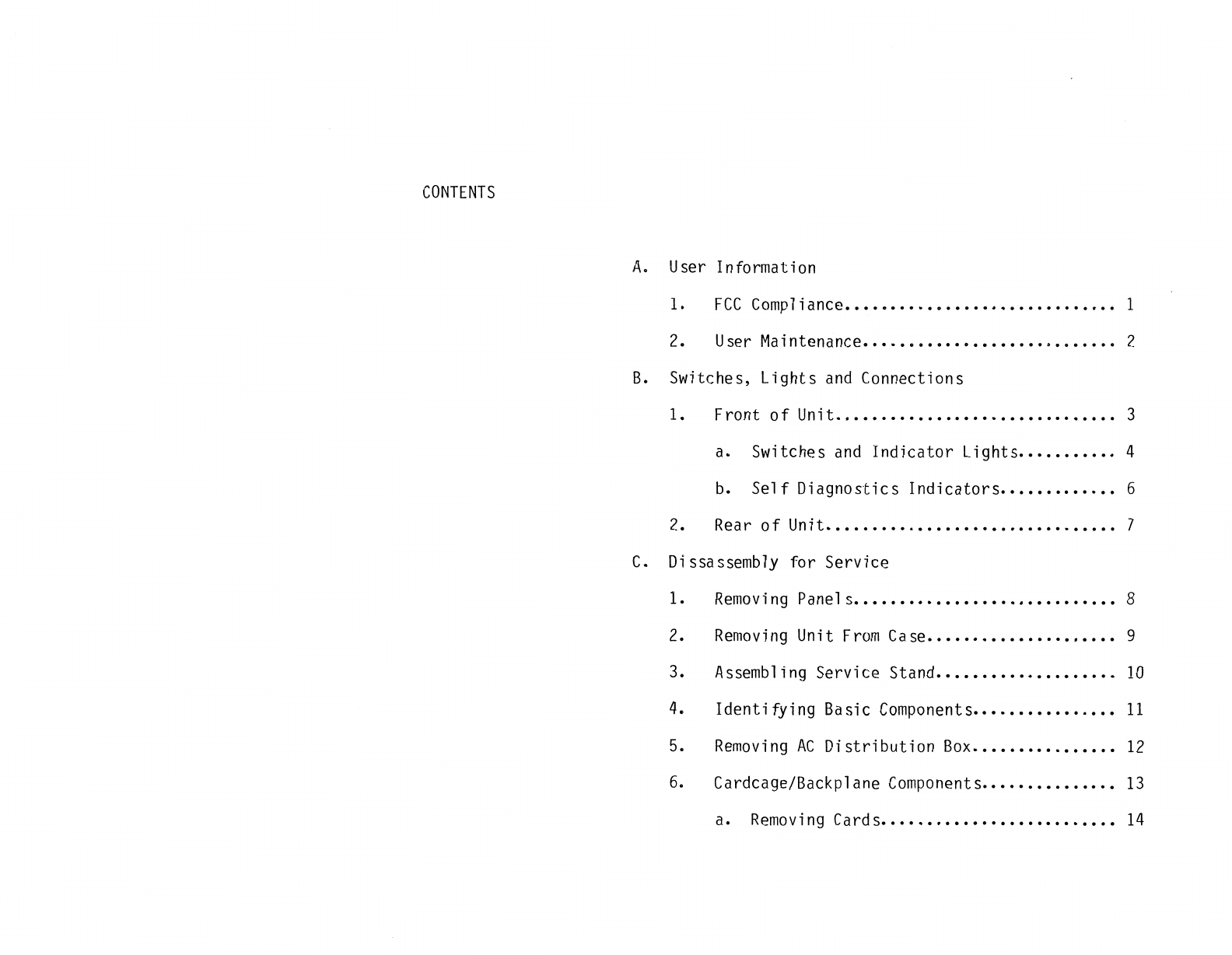
CONTENTS
A.
User Information
1.
FCC
Compliance
••••••••••••••••••••••••.••.•.
1
2.
User
Maintenance
...............•............
2
B.
Switches, Lights
and
Connections
1. Front
of
Unit
•••••..•.•••••••••••••••••••.•.
3
a. Switches
and
Indicator
Lights
••••.••••••
4
b.
Self
Diagnostics
Indicators
••••••..•.•••
6
2.
Rear
of
Unit
•••••.••••••••.•••••••••••••••••
7
C.
Di
ssassembly for Service
1.
Removing
Panels
.............................
8
2.
Removing
Unit
From
Case
•••••••••••••••••••••
9
3. Assembling Service Stand
••••••••.•••••••••••
10
4.
Identifying
Basic
Components
•••••.••••••••••
11
5.
Removing
AC
Distribution
Box
•.••••••••••••.•
12
6.
Cardcage/Backplane
Components
•••••.•••••••••
13
a.
Removing
Cards
•••••••••••••.••••••..••••
14
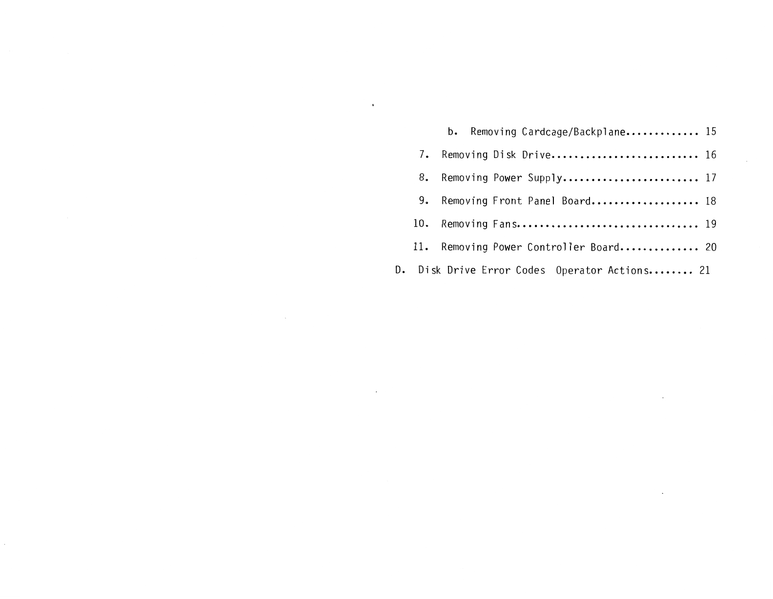
b.
Removing
Cardcage/Backplane
•••••••••••••
15
7.
Removing
Disk
Drive
..........................
16
8.
Removing
Power
Supply
........................
17
9.
Removing
Front
Panel
Board
•••••••••.••.•••.•.
18
10.
Removing
Fans
••••••••••••••••
11
•••••••••••••••
19
11.
Removing
Power
Controller
Board
•••••.•••••.••
20
D.
Disk
Drive Error
Codes
Operator Actions
.•••••••
21

Version 1.0
Version 2.0
Publication History
Aug.
l,
1984
Nov.
28,
1984
,
Original Version
Added
explanation to
40MB
Error
Codes
section
SWITCHES,
LIGHTS
AND CONNECTIONS...

F-CC
Compliance
This equipment
generates
and
uses radio frequency energy
and
if
not
installed
and
used
properly,
i.e.,
in
strict
accordance with
the operating
instructions,
reference
manuals,
and
the service
manual,
may
cause
interference
to
radio
or
television
reception.
It
has been
tested
and
found
to
comply
with the
limits
for a
Class A computing device pursuant
to
Subpart J
of
Part
15
of
FCC
Rules,
which
are designed
to
provide reasonable
protection
against
such
interference
when
operated in a commercial
installation.
If
this
equipment does cause
interference
to
radio
or
television
reception,
which
can
be
determined
by
turning the
equipment
off
and
on, the user
is
encouraged to
try
to
correct
the
interference
by
one
or
more
of
the following measures:
1)
Reorient the
receiving
antenna.
2}
Relocate
the
equipment with
respect
to
the
receiver.
3)
Move
the equipment
away
from
the
receiver.
4)
Plug the equipment
into
a
different
outlet
so
that
equipment
and
receiver
are
on
different
branch
circuits.
If
necessary,
consult
your
dealer
service
representative
for
additional suggestions.
The
manufacturer
is
not
responsible
for
any
radio
or
TV
interference
caused
by
unauthorized
modifications
to
this
equipment.
It
is
the
responsibility
of
the
user to
correct
such
interference.
1

User
Information
...
Dl5K_
Df11VE
FRONT
PANEL
FILTEJ\
o~
o~
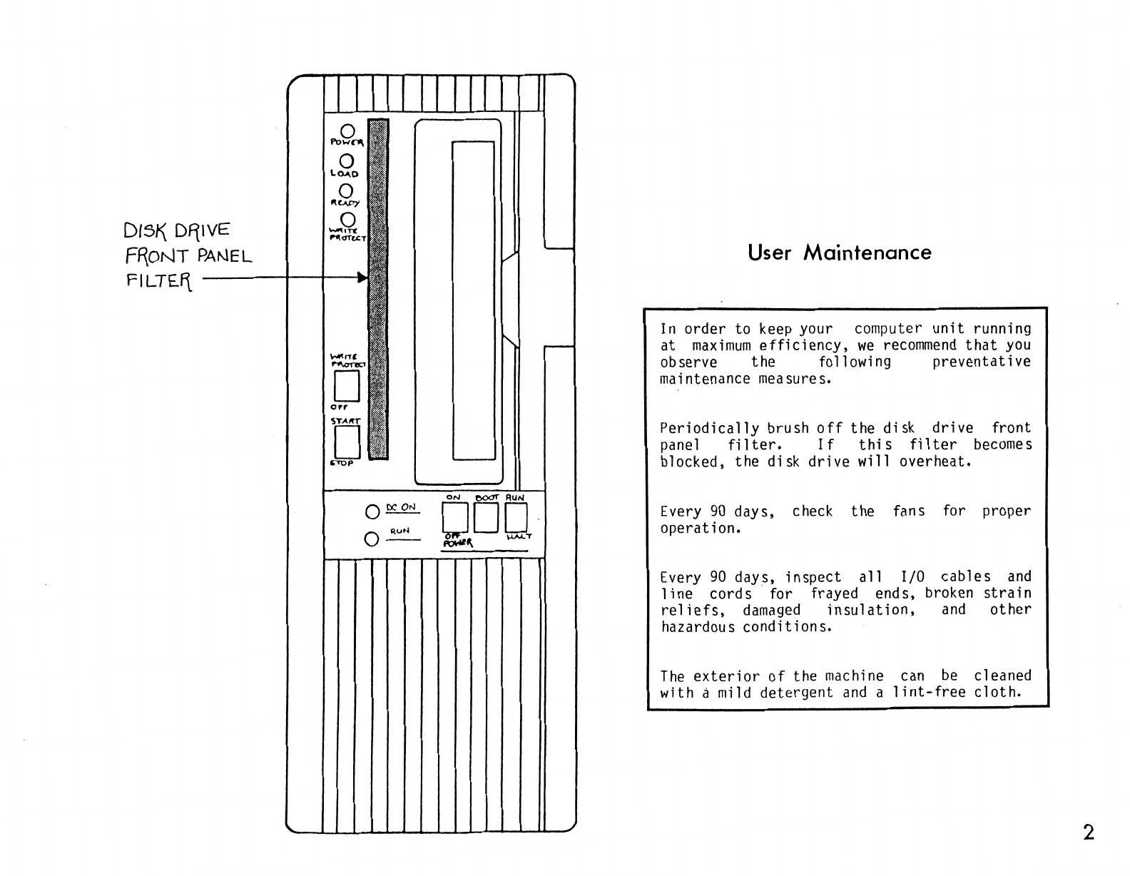
User
Maintenance
In
order to keep your computer
unit
running
at
maximum
efficiency,
we
recommend
that
you
observe the following
preventative
maintenance measures.
Periodically
brush
off
the
disk
drive
front
panel
filter.
If
this
filter
becomes
blocked, the disk
drive
will overheat.
Every
90
days, check the fans for proper
operation.
Every
90
days,
inspect
all
I/0
cables
and
line
cords·
for frayed ends, broken
strain
reliefs,
damaged
insulation,
and
other
hazardous
conditions.
The
exterior
of
the machine can
be
cleaned
with a mild
detergent
and
a
lint-free
cloth.
2
INDICATOR
LI
C:JHTS
DISK
POWER
-----+--t.-M1
LOAD
READY
-------.+--i~
w
RITE
PROTECT
-----+--1--Mii
ROCKER
SWITCHES
WRITE
'PROTEC.T
DISK 5TART/STOP
"""•ff
1"11<rn:.cT
INDICATOf3
Ll§HIS
DC
POWE~
ON
C.PU
~UN/HALT
----+-.+--..t,
·.
~
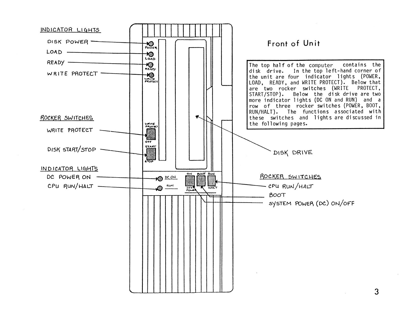
Front
of
Unit
The
top
half
of
the computer contains the
disk drive.
In
the top left-hand corner
of
the unit are four
indicator
lights
{POWER,
LOAD,
READY,
and
WRITE
PROTECT).
Below
that
are
two
rocker switches
(WRITE
PROTECT,
START/STOP).
Below
the disk drive are
two
more
indicator
lights
(DC
ON
and
RUN)
and
a
row
of
three rocker switches
(POWER,
BOOT,
RUN/HALT).
The
functions associated with
these switches
and
lights
are discussed in
the following pages.
Dl51\
DR\YE
BOCKER
sw r"fCl-\E:S
t-t--1[-----
CPU
RUN/HALI
--'---'...__
BOOT
5'f5TEM
POWE~
(DC)
ON/of"F
3

DC..
ON
Ll~HT
~"'
M\ons;T
D
orr
[]
..mp
Ru
N L\qi-\T
---t----t---Nli?lili
Switches
and
Indicator
Lights
The
POWER
switch,
located
below
the
disk
drive,
controls
all
the
DC
power
in
the
system.
When
the
power
is
ON,
the
DC
ON
indicator
light
(to
the
left
of
the
switch)
should
be
1
it.
The
BOOT
switch,
located
to
the
right
of
the
POWER
switch,
should
be
depressed
only
when
starting
up
the
computer
from
a
halted
state.
The
RUN/HALT
switch,
located
to
the
right
of
the
BOOT
switch,
controls
the
central
processing
unit.
It
will
normally
be
in
the
RUN
position
when
the
computer
is
operating.
The
RUN
indicator
light
(to
the
left
of
the
switches) should
be
green
and
red
when
the
computer
is
running.
~--+---RuN/HALT
6WITC.I-\
------BooT
6w1TCH
---..----
'-+--+--++--+---DC.
POWER
5WITC~
4
f\?WER
U
~HT
---+--t--11m
LOAD
LlqHT
READY
LI
q
I-ff
---t--+-M~
(llLINKINC:f)
WRITE.
PROTEC.T
L\Ej~Tt--+--.i
'"-"'lone
1'1'<1Te<:T
W~
ITE.
PROTECT
_-ir--t-ti
SWITCH
DI$}<\
SfART/5TOP-t--H
SWITCH
o~
o~
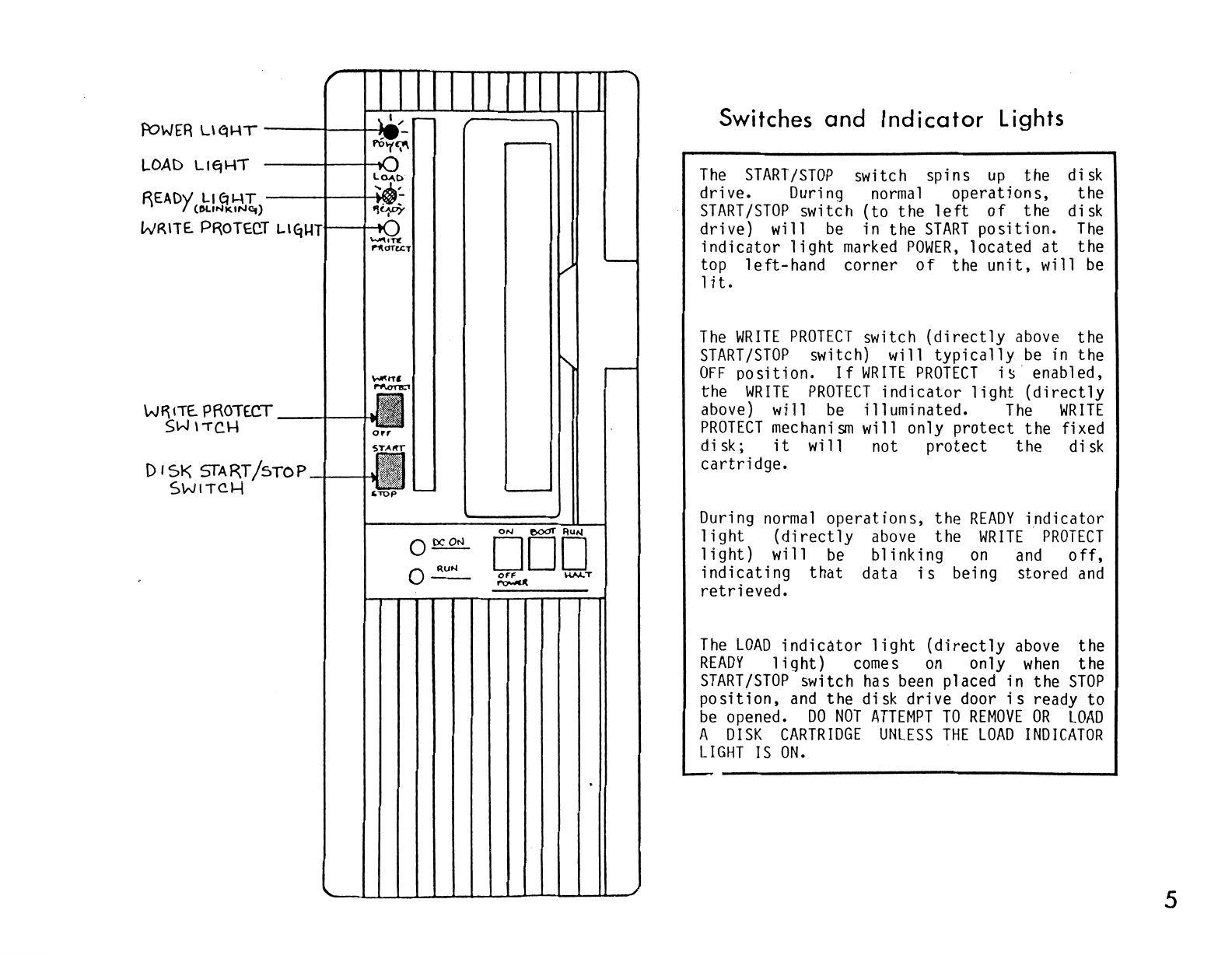
Switches
and
Indicator
Lights
The
START/STOP
switch spins
up
the disk
drive. During
normal
operations, the
START
/STOP
switch (to the
left
of
the disk
drive) will
be
in the
START
position.
The
indicator
light
marked
POWER,
located
at
the
top
left-hand
corner
of
the
unit,
will
be
1
it.
The
WRITE
PROTECT
switch
(directly
above
the
START/STOP
switch) will
typically
be
in the
OFF
po
sit
ion.
If
WRITE
PROTECT
i
!:>
enab
1ed,
the
WRITE
PROTECT
indicator
light
(directly
above) will
be
illuminated.
The
WRITE
PROTECT
mechanism
will only
protect
the fixed
disk;
it
will not
protect
the disk
cartridge.
During
normal
operations,
the
READY
indicator
light
(directly
above
the
WRITE
PROTECT
light)
will
be
blinking
on
and
off,
indicating
that
data
is
being stored
and
retrieved.
The
LOAD
indicator
light
(directly
above
the
READY
light)
comes
on
only
when
the
START/STOP
switch
has
been
placed in the
STOP
position,
and
the disk drive door
is
ready to
be
opened.
DO
NOT
ATTEMPT
TO
REMOVE
OR
LOAD
A
DISK
CARTRIDGE
UNLESS
THE
LOAD
INDICATOR
LIGHT
IS
ON.
5
DISASSEMBLY
FOR
SERVICE
...
....
Q
..
~"'!.
,_,
-···-
-,.
:::9:..
f~H--t---+---t---
B
\T
L\
LOJ\D
·~ww:·
1
t-t--r--t---
BIT
j_
~ll'C
r"f\<1fc.t:T
I
-
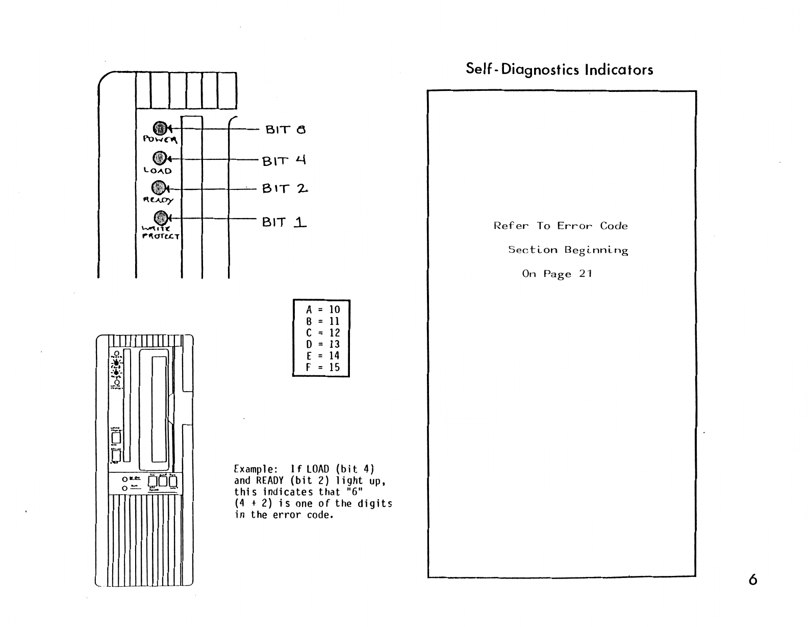
A =
10
B =
11
c =
12
D =
13
[ =
14
F =
15
Example:
If
LOAD
(bit
4)
and
READY
(bit
2)
light
up,
this
indicates
that
"6"
(4
+
2)
is
one
of
the
digits
in the
error
code.
Self-
Diagnostics Indicators
Refer
To
Error
Code
On
Page
21
6

AIR
INTAKE
BLANK
C.OVEf{
(NO-T
USED)
Rear
of
Powerframe
At
the top
of
the
rear
panel
is
a screen.
This
is
an
air-intake.
Below
the
air-intake
are
three
similarly
sized panels.
The
Computer
system has
two
25-pin
"male" connectors in the top panel.
These
two
ports
are the console
ports.
The
Model
1-0040 will normally
have
covers over these
two
positions.
The
Model
1-2340 will
typically
have
a
small
rectangular
plate
on
the port
farthest
to the
right
and
another
plate
immediately to
its
left.
In
certain
cases,
a bus extension connector will
be
installed
on
the
right,
and
a disk extension
connector
may
be
installed
to
its
immediate
1
eft.
The
small
rectangular cover to the
left
of
the
RS232
connectors covers a hole
that
does not
presently
have
a designated
use.
SECOND
PANE.L
WITH
8ADDITIONAL
-
--'-"--~
r
.............
} ,
............
,
.
\'...........
.
...
..........
.
2S-PIN
CONNt:C.TOR5
If
a "multiplexer" option has been
installed,
there
will
be
eight
additional 25-pin
connectors located in the second panel •
fOR
MULT1PLEX£R
OPTION.
NOTE.:
MODEL
1.-23LJO
S\-\OWN
ONjofF
SWITC.l--t
11
1"
•ON
"0'' "'OFF
FU5E
HOLDER
-----
•
@j3
••
@jjjjj) •
·······-···
·········-·
®
TH
IRD
PANEL
SLOT
(UNU5E:D)
The
third
large panel
is
a blank cover
and
does not presently
have
a designated use.
At
the bottom
of
the machine
on
the far
right-hand side
is
the
unit's
serial
tag.
To
the
left
of
the
serial
tag
is
the input
socket for
AC
power,
and
directly
above
that
is
the
ON/OFF
switch
("l"
indicates
"ON";
"O"
indicates
"OFF").
To
the
left
of
this
is
the fuse holder.
WARNING:
For continued
protection
against
risk
of
fire,
replace
only with the
same
type
and
rating
of
fuse.
5ER1Al-TA<::f
'-----t-f--1--1----
AC
A::>Wl:.R
IN
PUT
~De.KET
7

·
ITll
Ill
g
DOD
g
DOD
A1
0 0
0
IF
NECESSAR)',
USE
A SCREW
DRIVEf\
TO
6fNTLY
PRY
Tl-\E
PANELS
LOOSE.
.___
REMOVINq FF\ONT PANEL
REMOVINg
F\EAR
PANE"L
Removing Panels
If
AC
power
i s not needed for
the
POWER
switch
at
the
back
and
unplug the
line
cord
receptacle.
se
r
vi
cing,
turn
of
the unit
OFF
from
the
wa
11
To
remove
the front panel, grasp the panel
at
the top
and
the bottom
and
pull
it
straight
off.
It
may
be
necessary
to
use
a
screwdriver to pry
it
off.
If
so,
insert
the
screwdriver between the panel
and
the case
at
the top
rear
of
the front panel.
Pry
the
panel
off
gently
to
avoid
damaging
the case.
Repeat
this
procedure
at
the bottom
of
the
panel.
The
rear
panel
may
be
removed
in the
1
same
manner.
WARNING:
No
operator-serviceable
parts
inside
unit.
8
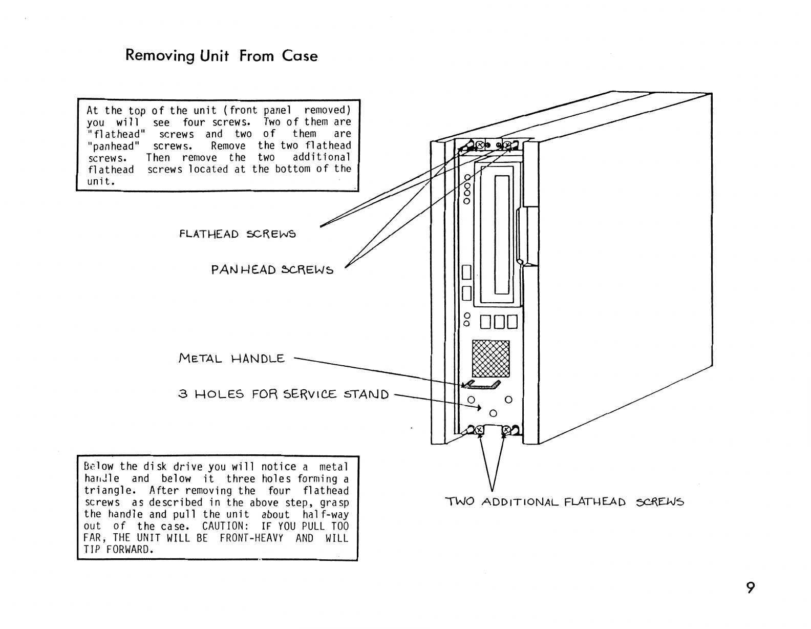
Removing Unit
From
Case
At
the
top
of
the
unit
(front
panel removed)
you
will
see four screws.
Two
of
them
are
"fl
at
head" screws
and
two
of
them
are
"panhead" screws.
Remove
the
two
flathead
screws.
Then
remove
the
two
additional
flathead
screws 1ocated
at
the
bottom
of
the
unit.
FLATHEAD
5CREWS
METAL
l-IANDLE
3
l-10LES
FOR 5ERv1C£ sTAf\JD
B~low
the
disk
drive
you
will
notice
a metal
har1Jle
and
below
it
three
holes
forming a
triangle.
After
removing
the
four
flathead
screws
as
described
in
the
above
step,
grasp
the
handle
and
pull
the
unit
about half-way
out
of
the
case.
CAUTION:
IF
YOU
PULL
TOO
FAR,
THE
UNIT
WILL
BE
FRONT-HEAVY
AND
WILL
TIP
FORWARD.
D
D
~====.JI
g
DOD
TWO
ADDITIONAL
FLATl-IEAD
ec~EJ.JS
9
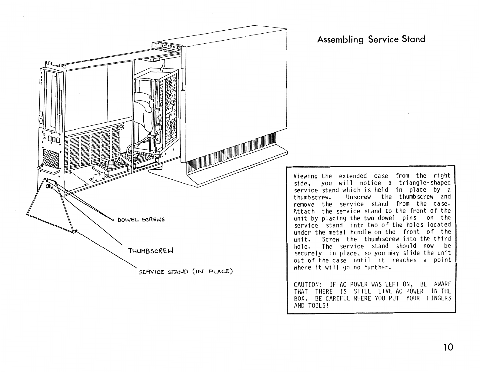
DOWEL
~REWS
St..f\VICE STAND
(1N
PLACE.)
Assembling Service Stand
Viewing
the extended case
from
the
right
side,
you
will notice a triangle-shaped
service stand
which
is
held in place
by
a
thumbscrew.
Unscrew
the
thumbscrew
and
remove
the service stand
from
the case.
Attach the service stand to the front
of
the
unit
by
placing the
two
dowel
pins
on
the
service stand into
two
of
the holes located
under the metal handle
on
the front
of
the
unit.
Screw
the
thumbscrew
into
thP.
third
hole.
The
service stand should
now
be
securely in place,
so
you
niay
slide the unit
out
of
the case
until
it
reaches a point
where
it
will
go
no
further.
CAUTION:
IF
AC
POWER
WAS
LEFT
ON,
BE
AWARE
THAT
THERE
IS
STILL
LIVE
AC
POWER
IN
THE
BOX.
BE
CAREFUL
WHERE
YOU
PUT
YOUR
FINGERS
AND
TOOLS!
10

FRONT PANEL BoARD
(
MOU
l\J
TE[)
BE\-\\
ND)
R:JW£R
COt-JTROLLE.R
6oARD
Identifying
Basic
Components
Dl5K
D~IVE
SERVtc..£
STAN.D
EXTRA:
:::.Lo-r
FoR
ACD11i1or-.JAL
FAN
-----------~!--
~CX!..EssoR
OOAR.D
(1!>1"
SLOT)
l-------=n11'RffitHl!ltl---
ME.MCRY BD.A..R.D
(2.JJ
D
SLOT)
DISK
cotJTRoLLtR
BC>ARD (3RD
sLOT)
AC
DISTRIBUTION
Box
The
disk
drive
left-hand
corner
viewed
from
the
be
1
ow
the
di
sk
is
located
in
the
top
of
the
extended
unit
when
right
side.
Immediately
drive
is
the
power supply.
Between
the
power supply and
the
front
panel
is
the
front
panel
board,
which
contains
the
switches
and
indicator
lights
discussed
on
page 2.
At
the
bottom
of
the
computer
are
two
cooling
fans
and
an
extra
slot
available
for
an
optional
fan.
To
the
right
of
the
fans,
at
the
back
of
the
computer
is
the
AC
distribution
box.
11
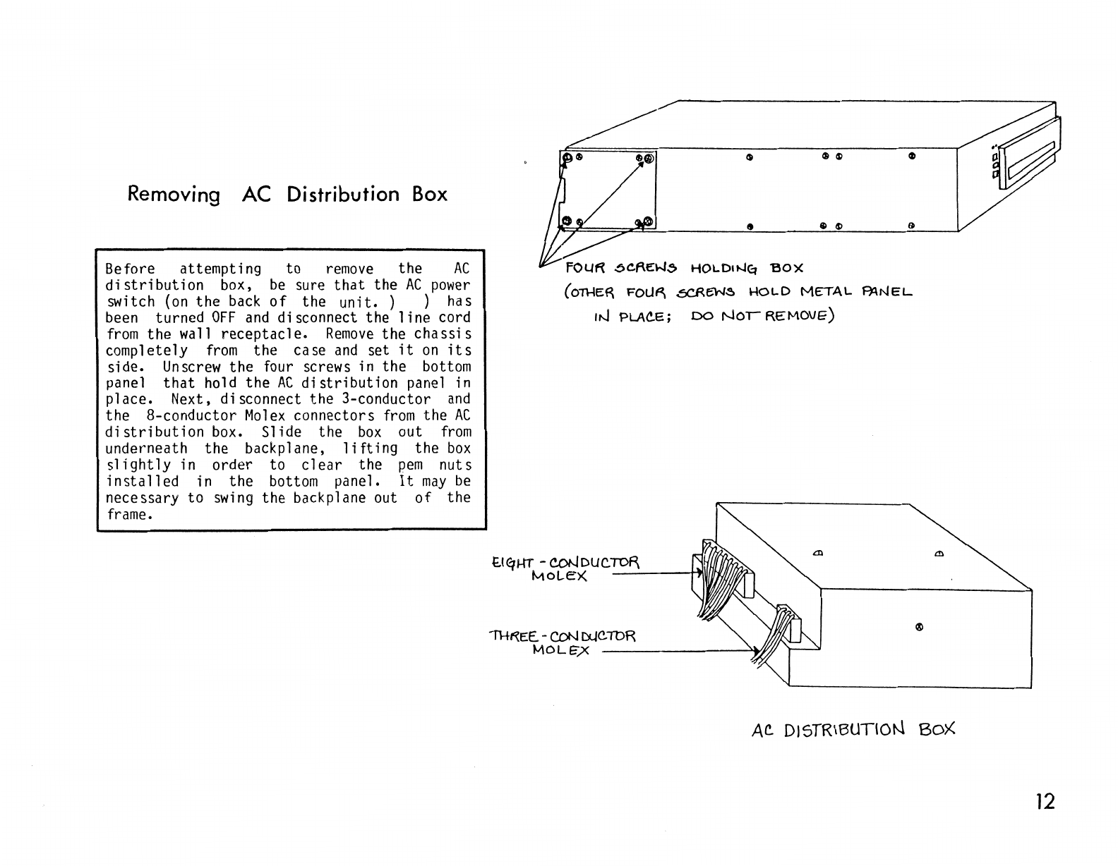
Removing AC Distribution Box
Before attempting to
remove
the
AC
distribution
box,
be
sure
that
the
AC
power
switch
(on
the
back
of
the
unit.
) ) has
been
turned
OFF
and
disconnect the
line
cord
from
the wall receptacle.
Remove
the
chassis
completely
from
the case
and
set
it
on
its
side.
Unscrew
the four screws in the
bottom
panel
that
hold the
AC
distribution
panel in
place. Next, disconnect the 3-conductor
and
the 8-conductor
Molex
connectors
from
the
AC
distribution
box. Slide the
box
out
from
underneath the backplane,
lifting
the
box
slightly
in order to
clear
the
pem
nuts
installed
in the
bottom
panel.
It
may
be
necessary to
swing
the backplane out
of
the
frame.
6C.f\Ei.-l,5>
HOLDOJEt
'BO)(
(o~ER
FOLJ~
.5CREW~
HOl-D
METAL
F):\NEL
IN
PLAC.E;
DO
NOi
REMOVE)
t.l<qHT -coNDUC.TOF\
MOLE>(
_....:...,_
__
~
1111
~
IH~EE.-CON
DUC.TbR
MOL~X
-------~ffff
AC.
DISTRIBUTION
Box
12
Other manuals for POWERFRAME
1
Table of contents


