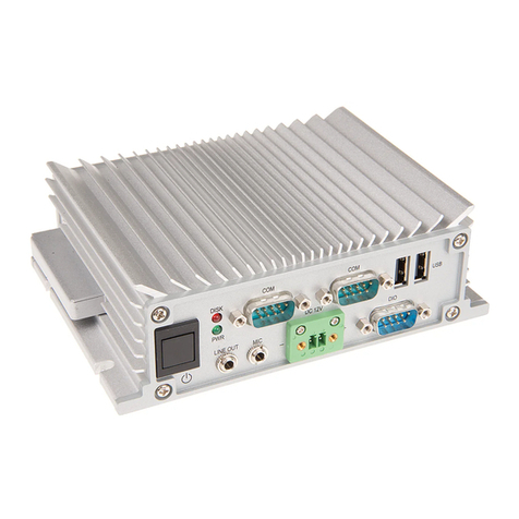
Forenex FES91W Series User manual

http://www.forenex.com.tw -3-
Record of version
FES91W User's Manual
Version
Revise Date
Page
Description
V1.0
V2.0
V2.1
V2.2
V2.3
2011-03-24
2011-07-30
2011-08-22
2013-01-13
2013-06-04
First issue
1.Dimension changed more 1mm in (D) side.(page 9)
2.Add VESA -75 hole in rear side.(page 9)
3.Add reset hole in rear side.(page 22)
4.Speaker connector change location(page 29).
5.Add SPI description.(page 48)
1.Add Section 2-4.2 Serial port Rs485 test
2.Add Section 4-5.3 Example code
1.Add PCL Printer Driver
2.Add SPI Write and Read of the lastTransfer
parameter (page 42-43).
3. Re-define the pin assignment of J7 & J9

http://www.forenex.com.tw -4-
General Description (FES91W series) ……………………………………….
.Appearance
.Order information
.Packing list
1. Specifications with FES91W series ………………………………………
1-1. Function Block Diagram
1-2. System Specifications
1-3. Mechanical Dimension
2. System Installations with FES91W series ………………………………………
2-1. Power Plugging
2-2. Touch installation
2-3. Debug Port installation
2-4. Serial port installation
2-4.1 Serial port Rs232 test
2-4.2 Serial port Rs485 test
2-5. Device USB installation
2-5.1 USB Connect test
2-6. Host USB installation
2-7. SD/MMC card installation
2-8. Extension Port installation
2-8.1 Port 2 installation
2-8.2 Port 1 installation
2-8.3 GPIO test
2-8.4 PWM test
2-8.5 ADC test
2.9 External stereo earphone installation
2-10. Internet installation
2-9.1 Internet setting
2-11. Wi-Fi installation (with an external dongle)
2-12. CAN BUS installation (with an external module)
3. FES91W series Programming Guide ………………………………………….
3-1 Function table
3-2 Function member description

http://www.forenex.com.tw -5-
4. Programming for FES91W ………………………….……….………
4-1 Install Visual studio 2005
4-1.1 Setup Development environment
4-1.2 Create New Project
4-1.3 Visual Basic Introduction.
4-2 GPIO Control
4-2.1 How to control GPIO for FES91W
4-2.2 Example code
4-3 PWM/ Backlight Control
4-3.1 How to control PWM/ Backlight for FES91W
4-3.2 Example code
4-4 ADC Control
4-4.1 How to control ADC for FES91W
4-4.2 Example code
4-5 Serial port Control
4-5.1 Overview
4-5.2 Member function of class SerialPort
4-5.3 Example code
4-6. SPI (Serial Peripheral Interface) Control
4-6.1 How to control SPI for FES91W
***The content of this document is subject to be change without notice***

http://www.forenex.com.tw -6-
General Description (FES91W series)
●Order information
• OS type ID: (FES91〝W〞xx-xxx).
• FES91Wxxx-xxx : Embedded WinCE 6.0.
Standard
Processor type
Memory size
Function
option
Panel type
FES91Wxx-xxx
FES91Wxx-xxx
FES91WXx-xxx
FES91WxX-xxx
FES91Wxx-XXX
CPU:AT91SAM9M10
FES91Wxx-xxx
64MB
FES91W0x-xxx
128MB
FES91W1x-xxx
WLAN
FES91WxA-xxx
CAN BUS
FES91WxB-xxx
WLAN
& CAN BUS
FES91WxC-xxx
800x480
FES91Wxx-070
800x600
FES91Wxx-080
1024x768
FES91Wxx-104
●Packing List
•FES91W series device with metal housing.
•Download Cable: USB-A male to mini-5p USB with 70cm length.
Numbering: WYUSBMINI500900
•Debug cable: header housing (2x5pin) to D_sub9 female connector.
Numbering: WH810B090173
•Utility software CD (including example program code).

http://www.forenex.com.tw -7-
1.Specifications (FES91W series)
1.1 Function Block Diagram
NAND Flash
SD/MMC
Card
DDR2
ADC x 4
Wi-Fi (WLAN)
Option
10/100 Ethernet
RJ45
Extension Port 1
COM2
D-SUB9
Male
RS232/485
GPIO x 16
PWM x 2
Extension Port 2
SPI0
SPI1
COM4
CAN BUS Option
LCD
Touch
4-wire
COM3
D-SUB9
Male
RS232/485
USB
A type
Audio
Codec
Stereo
AMP
CPU
(ARM926EJ/400MHz)
Atmel AT91SAM9M10
EEPROM
DC/DC
DC9 ~ 28V

http://www.forenex.com.tw -8-
1.2 System specifications
Parameter
Specification
CPU
■ Atmel AT91SAM9M10 @ 400MHz
■ 32 bit RISC architecture ARM926EJ core
System Memory
64MB or 128MB, DDR2 memory.
Storage Memory
2Gbit NAND Flash memory.
OS
■ Embedded WinCE 6.0.
LCD Panel
■ -070: 7” TFT LCD, 800x480, 400 cd/㎡, CR:500, 16M color.
■ -080: 8” TFT LCD, 800x600, 250 cd/㎡, CR:500, 16M color.
■ -104: 10.4” TFT LCD, 1024x768, 250 cd/㎡, CR:500, 16M color.
Video Hardware
Decoder
Support MPEG1/2/4, H.264,VC-1 Hardware decoder.
For FES91 series only
Touch
4-wired resistive type.
LAN
High performance RMII 10/100Mbps Ethernet controller.
Audio
■AC97 Codec, AMPinside for Ext. Stereo speaker 8Ohm/1W.
■Stereo Earphone Jack.
SD Slot
SD/MMC card.
Serial Port
■5 wire RS232 x 1 (COM2 connector sharing with RS485/422).
■3 wire RS232 x 1 (COM3 connector sharing with RS485/422).
■3 wire RS232 x 1 (COM4 located in Extension Port).
USB
■ USB 2.0 device x 1.
■ USB 2.0 Host x 1.
Extension Port1
■ Including programmable IO x 16 pin.
■ Including 10 bit high speed A/D converter channel x 4.
■ Including PWM channel x 2.
Extension Port2
■ Including SPI port x 2 (slave or master mode).
■ COM4 (3 wire RS232 only).
WiFi option
IEEE802.11 b/g/n, WiFi compliant (under development with an
external dongle)
CAN BUS option
(under development with an external module)
Power Supply
DC9V ~ 28V single power input.
Operating
Temperature
-20 ℃~ 80℃

http://www.forenex.com.tw -10-
2.System installation (FES91W series)
2.1 Power Plugging
Or
2.2 Touch installation
The following steps show how to use Coordinate calibration.
STEP 1. On Windows CE desktop, click on “My Device”.
STEP 2. Select “NandFlash” folder.
9 ~ 28V/1A
equivalent
Power jack
equivalent
+12
GND

http://www.forenex.com.tw -13-
2.3 Debug Port installation
Debug port is only available for internal use. User’s application program is unavailable.
Setup HyperTerminal
Using HyperTerminal on PC end can read information from FES91W or input command to
FES91W.
●It was necessary that PC connect with FES91W.
The following steps show how to setup HyperTerminal on PC end.
STEP 1. Run the HyperTerminal on PC.
Pin1
Pin6
Pin2
Debug_RX
Pin7
Debug_RTS
Pin3
Debug_TX
Pin8
Debug_CTS
Pin4
Pin9
Pin5
GND
Pin10
Debug Port
Header 2x5pin, pitch 2.0mm
PC or equivalent
Cable: WH810B090173

http://www.forenex.com.tw -14-
STEP 2. Select the applicable COM port, click OK.
●To find applicable COM port, click Control panel –> system –> hardware –> device
manager –> COM&LPT ports.
STEP 3. Port Settings
Bits per second (or Baud rate): 115200, Data bits: 8, Parity: None, Stop bits: 1,
Flow control: None. Click Apply, and then OK.

http://www.forenex.com.tw -16-
2.4 Serial port installation
FES91W supports three sets of RS232 or two sets of RS485 (option) or two sets of
RS422 (option).
COM2
●The port (COM2) provided 5-wire RS232 on D_SUB9-male connector.
●The connector D_SUB9 is shared with the signals of RS485/422.
●Due to a terminating resistor 120 Ohm has been installed inside. COM2 has
to enable as master or the last slave device while COM2 be dedicated to work
with mode RS485/422.
●Both working mode of RS232 and RS485/422 can not be enabled in simultaneously.
COM2
D_SUB9/male
COM2
PC or equivalent
PC_Rx
TX1
RX1
RTS1
CTS1
A1/Y1
B1/Z1
PC_Tx
PC_CTS
PC_RTS
PC_A/Y
PC_B/Z
GND
GND

http://www.forenex.com.tw -17-
COM3
● The port (COM3) provided 3-wire RS232 on D_SUB9-male connector.
● The connector D_SUB9 is shared with RS485/422 format.
● Due to a terminating resistor 120 Ohm has been installed inside. COM3 has
to enable as master or the last slave device while COM3 be dedicated to work
in mode RS485/422.
● Working mode RS232 and RS485/422 can not be enable in simultaneously.
COM4
●The port (COM4) provided 3-wire RS232 on two pin headers of extension port2.
PC_Rx
PC_Tx
RX3
TX3
GND
GND
COM3
D_SUB9/male
COM3
PC or equivalent
Header 2x7pin, pitch 2.0mm
Extension Port2
COM4
COM4
PC or equivalent
PC_Rx
TX2
RX2
A2/Y2
B2/Z2
PC_Tx
PC_A/Y
PC_B/Z
GND
GND

http://www.forenex.com.tw -18-
2-4.1> Serial port Rs232 test
The following steps show how to set HyperTerminal at PC end.
STEP 1. Run the hyper-terminal on PC.
STEP 2. Select the applicable COM port, click OK.
●To find applicable COM port, click Control panel –> system –> hardware –> device
manager –> COM&LPT ports

http://www.forenex.com.tw -19-
STEP 3. Make sure the “Bits per second” (or Baud rate) ranges from 9600 to 115200
and ”Flow control” settings “None”. Click on apply, then OK.
●Steps of PC end is complete.
Below steps guide is use Serialport-ap at Windows CE.
STEP 1. On Windows CE desktop, click on “My Device”.
STEP 2. Select “NandFlash” folder.
This manual suits for next models
8
Table of contents
Other Forenex Desktop manuals


