Forenex FEB600 User manual

-1-
FEB600 User Manual
FEB600-Q/D/U
ARM BOX PC
User Manual
(Preliminary)
Fanless ultra-compact quad core
ARM system ruggedized for
extreme environments
Version: V1.0
Document No: doc-FEB600x-V10
PCB Bare Board: PB630868-V10

-2-
FEB600 User Manual
Packing List
1 x FEB600 device.
1 x Terminal Block to DC Jack.
Ordering Information
Part number : FEB600-xyz-m-n-MN
•xyz : The feature code of Processor
Q10 Fanless ARM system with 1.0GHz NXP i.MX 6Quad Cortex-A9 SoC.
D10 Fanless ARM system with 1.0GHz NXP i.MX 6Dual Cortex-A9 SoC.
U10 Fanless ARM system with 1.0GHz NXP i.MX 6DualLite Cortex-A9 SoC.
• m: The size code of DDR3 Memory on board
1 1GB of DDR3.
2 2GB of DDR3.
• n: The size code of eMMC on board
4 4GB of eMMC.
8 8GB of eMMC.
F 16GB of eMMC.
•MN : The Function Summary code
SS HDMI, 3x USB2.0, Mini USB 2.0 OTG, 1x COM, Micro SD socket, CANbus &
Debug port, GPIO, Gigabit Ethernet, line-out/MIC-in, DC12V-in.
PS HDMI, 3x USB2.0, Mini USB 2.0 OTG, 1x COM, Micro SD socket, CANbus &
Debug port, GPIO, Gigabit Ethernet, line-out/MIC-in, DC12V-in,
PoE (802.3af/ PD mode A/ endspan only )
Optional Accessories
Part Number Description
EP21-B4356C AP12356,802.11 a/b/g/n/ac(2T2R)+BT(V4.1 LE), mPCIe Wifi
module.
WFS001I401nnnO8 SMA(ST. JR)to IPEX(IV) cable, 50Ω, nnn=130/230/400mm.
LN1RF2G20M0 2.4/5Ghz, 2dBi-antenna, SMA(ST. PR), bendable, 110mm.

-3-
FEB600 User Manual
Revision histories
Rev. No.
Date
Substantial Changes
1.0
2018/06
First issue.

-4-
FEB600 User Manual
Table of Contents
1. General Information ........................................................................................................ 6
1-1. Features .............................................................................................................................. 6
1-1-1. ARM based System ............................................................................................................ 6
1-1-2. Ultra compact, Ruggedized and Fanless ............................................................................ 6
1-1-3. The Operating Temperature .............................................................................................. 6
1-1-4. Storage Expansion.............................................................................................................. 7
1-1-5. Networking Option ............................................................................................................ 7
1-1-6. Power over Ethernet option .............................................................................................. 7
1-1-7. Embedded OS ready........................................................................................................... 7
1-2. Product Specifications......................................................................................................... 8
1-3. Outline Dimensions........................................................................................................... 10
1-3-1. Front view ........................................................................................................................ 10
1-3-2. Top view........................................................................................................................... 10
1-3-3. Rear view.......................................................................................................................... 10
1-4. Peripherals Port layout diagram ....................................................................................... 11
1-4-1. Front Panel....................................................................................................................... 11
1-4-2. Rear Panel ........................................................................................................................ 11
2. Peripherals Port Description.......................................................................................... 12
2-1. DC-in Jack .......................................................................................................................... 12
2-2. LEDs Indicator ................................................................................................................... 12
2-3. Micro SD/eMMC boot select switch ................................................................................. 12
2-4. COM1 Port ........................................................................................................................ 13
2-5. Gigabit Ethernet Port ........................................................................................................ 13
2-6. Reset Button ..................................................................................................................... 14
2-7. USB 2.0 Port ...................................................................................................................... 14

-5-
FEB600 User Manual
2-8. Mini USB OTG Port............................................................................................................ 14
2-9. CAN/Debug Port................................................................................................................ 15
2-10. Micro SD/SDHC card Slot .................................................................................................. 15
2-11. DIO port............................................................................................................................. 16
2-12. MIC with Stereo Jack......................................................................................................... 16
2-13. Headphone with Stereo Jack ............................................................................................ 16
2-14. HDMI®-1.4 port ................................................................................................................. 17
3. Software and Technical Supports .................................................................................. 18
3-1. Android Programming Guide ............................................................................................ 18
3-1-1. ADB installation........................................................................................................ 18
3-1-2. GPIO installation....................................................................................................... 20
3-1-3. CANbus installation .................................................................................................. 21
3-1-4. COM port installation and Sample code .................................................................. 22
3-2. Linux Programming Guide................................................................................................. 22
3-2-1. GPIOs installation ..................................................................................................... 22
3-2-2. CANbus installation .................................................................................................. 23
3-2-3. COM port installation and Sample code .................................................................. 24

-6-
FEB600 User Manual
1.General Information
The FORENEX FEB600 BoxPC is an ultra-compact solution designed to take full advantage of
ARM-based ultra-energy-saving and easily create a variety of easy-to-assemble, fanless system
designs for a wide range of industrial automation, transportation, HMI and energy management
applications.
The FEB600 is a completely fanless system. Its rugged design can endure a wide operating
temperature range of -20 °C to 70 °C, and it consumes extremely low power under typical operating
conditions. In addition, an optional miniPCIe slot is provided for 5G / Wi-Fi connection.
Comprehensive I / O functions on the front and rear panels make the FEB600 a flexible solution for a
variety of embedded applications.
The heart of the FEB600 PC box is the i.MX 6Quad/Dual/DualLite processor which provides all of the
interfaces necessary for connecting peripherals such as:
-Networking: RJ45 Gigabit Ethernet port, an optional miniPCIe Wi-Fi(WLAN) connectivity.
-Serial port: Mini USB 2.0 OTG port, USB 2.0 port, COM1/485/422 port, CAN/Debug port.
-Display: HDMI® 1.4 port.
-Audio: Stereo Line-out jack, MIC-in jack.
-Expansion storage & GPIO: Micro SD slot, DIO port.
-Others: Micro SD/eMMC boot select switch, reset button, power LED, Wi-Fi LED.
1-1. Features
1-1-1. ARM based System
ARM based Pico-ITX alike board with an NXP i.MX6 Quad (Dual or DualLite) Cortex-A9 ARM SoC,
offering high performance processing optimized for the lowest power consumption.
1-1-2. Ultra compact, Ruggedized and Fanless
The FEB600 fanless system is a 143mm (W) x 60mm (H) x 74mm (D) ruggedized chassis, which is
suitable to install in a space critical environment to ensure maximum reliability. The chassis design
has a ridged aluminum top cover does also acts as the heatsink of the NXP i.MX6 processor.
1-1-3. The Operating Temperature
This provide a wide range from -20°C up to 70°C, suitable for critical environment applications.
**Note: The Operating Temperature is a result of testing performed in an experimental chamber.
It is highly suggested to execute a solid testing under an actually application environment.

-7-
FEB600 User Manual
1-1-4. Storage Expansion
The Micro SD/SDHC card slot enables the FEB600 to have a flexible storage up to 32GB size.
**Note: More frequent and larger data access on eMMC memory makes its lifespan shorter.
Therefore, it is highly recommended to use a Micro SD card for large data access.
1-1-5. Networking Option
The FEB600 is equipped with RJ-45 port that supports high speed Gigabit Ethernet. An optional
miniPCIe slot is provided for 2.4G/5Ghz,Wi-Fi (WLAN) connectivity. The wireless module (Wi-Fi)
complies with IEEE 802.11a/b/g/n/ac 2x2 MIMO standard.
1-1-6. Power over Ethernet option
Integrated 802.3af, mode A (endspan) only, Powered Device (PD) controller and switching regulator
intended for high power IEEE 802.3at and 802.3af applications. The power over Ethernet (PoE) PD
board can output 15.4W of power. The FEB600 can be operated using either PoE or external
adaptors (12V).
1-1-7. Embedded OS ready
Android 6.0, Linux 4.1.15.
Yocto Project2.0 with QT 5.4 (Weston Wayland UI).

-8-
FEB600 User Manual
1-2. Product Specifications
Processor:
1.0GHz NXP i.MX 6Quad Cortex-A9 SoC (FEB600-Q10xx).
1.0GHz NXP i.MX 6Dual Cortex-A9 SoC (FEB600-D10xx).
1.0GHz NXP i.MX 6DualLite Cortex-A9 SoC (FEB600-U10xx).
System Memory:
2GB DDR3-1066 SDRAM onboard.
Storage:
8GB eMMC Flash memory.
Graphics:
Vivante GC2000 GPU (FEB600-Q10xx & FEB600-D10xx)
Two (identical) Image Processing Units (IPUs).
Supports HDMI 1.4 port.
Supports Hardware Graphics acceleration: OpenGL® ES 3.0, OpenCL and OpenVG™ 1.1.
Supports Hardware video acceleration: HD1080p60 Decode, Dual HD720p Encode.
Vivante GC880 GPU (FEB600-U10xx)
Two (identical) Image Processing Units (IPUs).
Supports HDMI 1.4 port.
Supports Hardware Graphics acceleration: OpenGL® ES 3.0, OpenVG™ 1.1.
Supports Hardware video acceleration: HD1080p30 Decode, Dual HD720p Encode.
LAN:
ATHEROS AR8031 Gigabit Ethernet transceiver with RGMII support.
WLAN: (Optional)
2.4G/5Ghz Wi-Fi module with miniPCIe interface. The wireless module complies with IEEE
802.11a/b/g/n/ac 2x2 MIMO standard.
Audio:
NXP SGTL5000 low power stereo codec.
USB:
MicroChip USB2514 USB 2.0 high speed 4-port hub controllers.
CAN:
MicroChip MCP2551T_I EMC optimized CAN transceiver.

-9-
FEB600 User Manual
Front Panel I/O:
1 x 2-pole Phoenix DC jack.
1 x Power LED & WLAN/WPAN/WWAN LED (if Wi-Fi has installed).
1 x COM1 port (supports 5-wire TX/RX/RTS/CTS) RS232 DTE mode/RS485/RS422.
1 x Gigabit Ethernet port (supports optional IEEE802.3 af type 1).
1 x Micro SD/eMMC boot select switch.
2 x Antenna holes for 5G/Wi-Fi.
Rear Panel I/O:
1 x Reset button.
1 x HDMI® port.
1 x Mini USB 2.0 type B port support OTG.
3 x USB 2.0 type A ports.
1 x Micro SD/SDHC card slot.
1 x CAN/Debug port supports one COM2(supports 2-wire TX/RX) and two CAN bus support
CAN Protocol specification Version 2.0 B) through a cable.
1 x DIO port supports eight GPIOs.
1 x Audio jack for Line-out(default)/Earphone-out(option).
1 x Audio jack for Mic-in(default)/Line-in(option).
Dimension (W x D x H):
143mm x 74mm x 60mm (5.6” x 2.9” x 2.4”).
Weight:
TBD.
Operating Temperature:
-20°C ~ 70°C.
Operating Humidity:
0% ~ 90% @ 45°C (non-condensing).
Operating System:
Android 6.0, Linux 4.1.15 (AMOS-820-QP SKU).
Yocto Project2.0 with QT 5.4 (Weston Wayland UI).

-10-
FEB600 User Manual
1-3. Outline Dimensions
1-3-1. Front view
1-3-2. Top view
1-3-3. Rear view
-11-
FEB600 User Manual
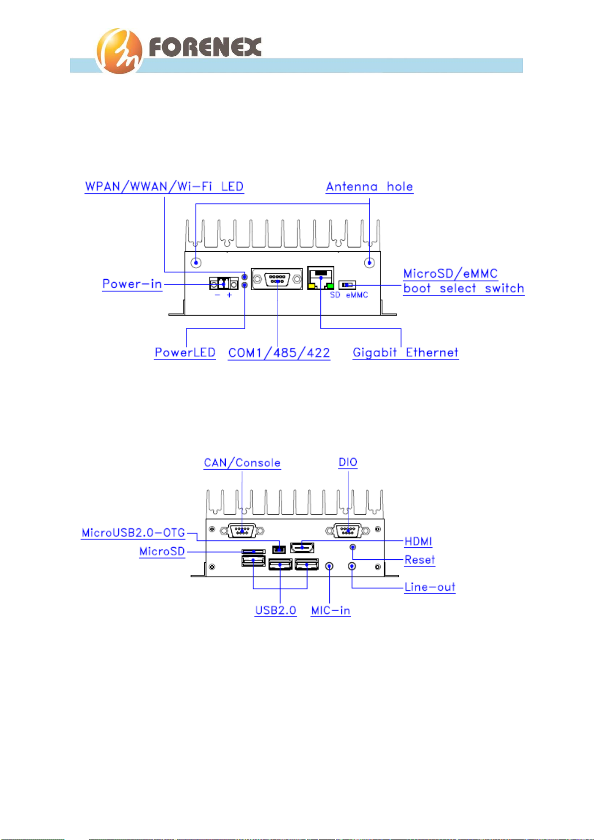
1-4. Peripherals Port layout diagram
1-4-1. Front Panel
1-4-2. Rear Panel

-12-
FEB600 User Manual
2.Peripherals Port Description
2-1. DC-in Jack
On front panel, carries external power input.
Pin Assignment:
2-2. LEDs Indicator
On front panel.
The green LED indicates the system’s power is plugged.
The red LED indicates the WPAN/WWAN status of the Wi-Fi module as installed.
2-3. Micro SD/eMMC boot select switch
On front panel.
The FEB600 comes with a boot select switch which allows users to select boot device from
Micro SD and eMMC.
Connector: ( 2-pole Phoenix DC Jack )
Pin number
Description
1
DC12V ~ 24V
2
GND
To boot from eMMC device
To boot from SD card

-13-
FEB600 User Manual
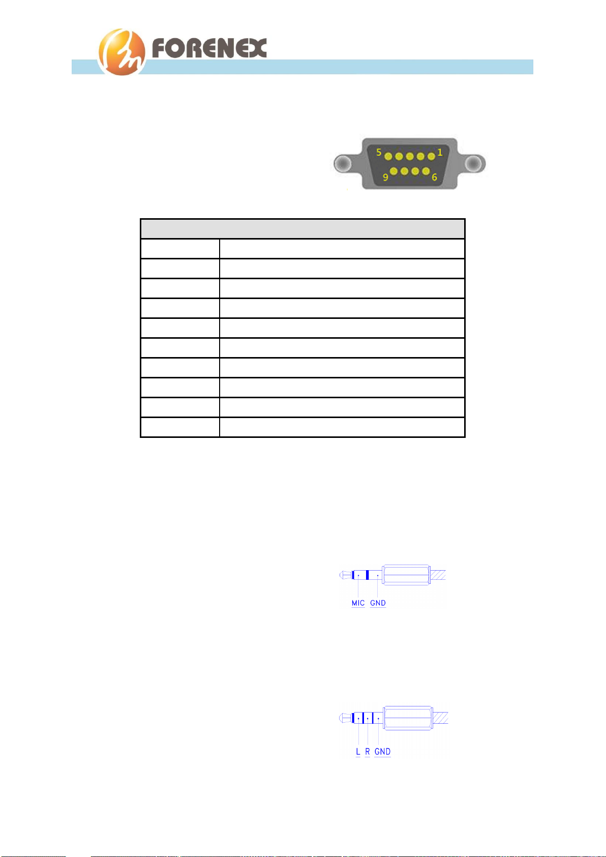
2-4. COM1 Port
On front panel.
The integrated 9-pin of COM1 port provides optional RS232/485/422 three operating
modes.
Please note the following!!!
-Even though the COM1 can be selected as RS232, RS422 or RS485 operating modes,
these absolutely cannot be used simultaneously.
-It is not allowed to use those pins which are specified with “DNC” in each individual
operating mode.
Pin Assignment:
“DNC”- means do not connection
2-5. Gigabit Ethernet Port
On front panel.
The integrated 8-pin Gigabit Ethernet port is using an 8 Position 8 Contact (8P8C)
receptacle connector (commonly referred to as RJ-45).
The Gigabit Ethernet port (RJ-45 port) has two individual LED
indicators located on the front side to show:
-Active LED is blinking in green color means activity of data flow
IN or OUT of the device.
-Link LED is in Red color means devices is operating in speeds 10/100Mbps.
Link LED is in Green color means devices is operating in speeds 1000Mbps.
Connector: ( DB-9/DTE-Male )
Pin number
RS232 mode
RS422 mode
RS485 mode
1
DNC
422-RX-A/Y
DNC
2
COM1-RX (SIN)
DNC
DNC
3
COM1-TX (SOUT)
DNC
DNC
4
DNC
422-TX-A/Y
485-A/Y
5
GND
GND
GND
6
DNC
422-RX-B/Z
DNC
7
COM1-RTS
DNC
DNC
8
COM1-CTS
DNC
DNC
9
DNC
422-TX-B/Z
485-B/Z

-14-
FEB600 User Manual
2-6. Reset Button
On rear panel.
Makes system warm start.
2-7. USB 2.0 Port
On rear panel.
The FEB600 provides three USB 2.0 ports. Each USB port gives complete hot plug
capability and complies with USB UHCI, Rev. 2.0.
Pin Assignment:
2-8. Mini USB OTG Port
On rear panel.
The Mini USB 2.0 OTG(On-The-Go) port.
The FEB600 is regarded as an USB device by default when connected to an USB host.
Pin Assignment:
Connector: ( USB Type A )
Pin number
Description
1
+5V
2
USB Data -
3
USB Data +
4
GND
Connector: ( Mini USB Type B )
Pin number
Description
1
VBUS
2
D-
3
D+
4
ID
5
GND

-15-
FEB600 User Manual
2-9. CAN/Debug Port
On rear panel.
The integrated 9-pin of CAN/Debug port uses a male DB-9 connector. The CAN bus port
supports CAN protocol specification Version 2.0 B while the Debug port supports TX/RX.
The purpose of the Debug port is for debug only.
Did not provide galvanic isolation.
Pin Assignment:
2-10. Micro SD/SDHC card Slot
On rear panel.
Micro SD/SDHC card slot without spring and enable the SD storage up to 32GB size.
Providing others OS boot from SD card.
Functions as an extra-storage device. Prevent more frequent and larger data access on
eMMC memory makes its lifespan shorter.
Connector: ( DB-9/Male )
Pin number
Description
1
COM-GND
2
Debug-RX (SIN), RS232 level
3
Debug-TX (SOUT), RS232 level
4
NC
5
COM-GND
6
CAN-GND
7
CANL
8
CANH
9
CAN-GND
-16-
FEB600 User Manual
2-11. DIO port
On rear panel.
Supports eight GPIOs without isolated
Pin Assignment:
2-12. MIC with Stereo Jack
On rear panel.
The MIC-in jack is a 3.5 mm connector for connecting to an external microphone.
The Jack can be re-defined to Line-IN before ordering
2-13. Headphone with Stereo Jack
On rear panel.
The Headphone Stereo jack is a 3.5 mm Tip Ring Sleeve (TRS) connector.
The Jack can be re-defined to Line Out before ordering.
Connector: ( DB-9/Female )
Pin number
Description
1
3.3V_GPO_3
2
3.3V_GPI_3
3
3.3V_GPO_2
4
3.3V_GPI_2
5
3.3V_GPO_1
6
3.3V_GPI_1
7
3.3V_GPO_0
8
3.3V_GPI_0
9
DIO-GND
-17-
FEB600 User Manual
2-14. HDMI®-1.4 port
On rear panel.
The HDMI port uses an HDMI Type A receptacle connector. It allows connecting the digital
video devices which utilize a high definition video signal without a HDCP.
Pin Assignment:
Connector: (19-pin HDMI Type A )
Pin number
Signal
Pin number
Signal
1
TMDA_Data2+
2
Data2_GND
3
TMDA_Data 2-
4
TMDA_Data1+
5
Data1_GND
6
TMDA_Data1-
7
TMDA_Data0+
8
Data0_GND
9
TMDA_Data0-
10
TMDA_CLK+
11
CLK_GND
12
TMDA_CLK-
13
NC
14
NC
15
DDC-SCL
16
DDC-SDA
17
CEC GND
18
Power 5V supply
19
Hot Plug Detect

-18-
FEB600 User Manual
3.Software and Technical Supports
3-1. Android Programming Guide
3-1-1. ADB installation
Enable USB debugging from Android environment of MBE60 :
1. Scroll to "Settings > About Tablet"
2. From “Settings” select "About tablet" to enter the dialog, and then click "Build
number" in the dialog as shown. Android will pop up a countdown message.
Keep clicking it until zero for Android to authorize the user to be a Developer.

-19-
FEB600 User Manual
3. After completing the above action, a new item "Developer Options" will
appear in the system block.
4. Next select "Developer Options" and turn on the USB debugging function.
Note: Please do not change the other settings if you do not understand what they
do.
To install APK software over the ADB function of PC. :
1. Complete the connectivity between USB-OTG port of MBE60 and USB port of
PC.
2. Enter the command string "adb install xxxxx.apk" from PC and to begin
-20-
FEB600 User Manual
user’s APK software installation.
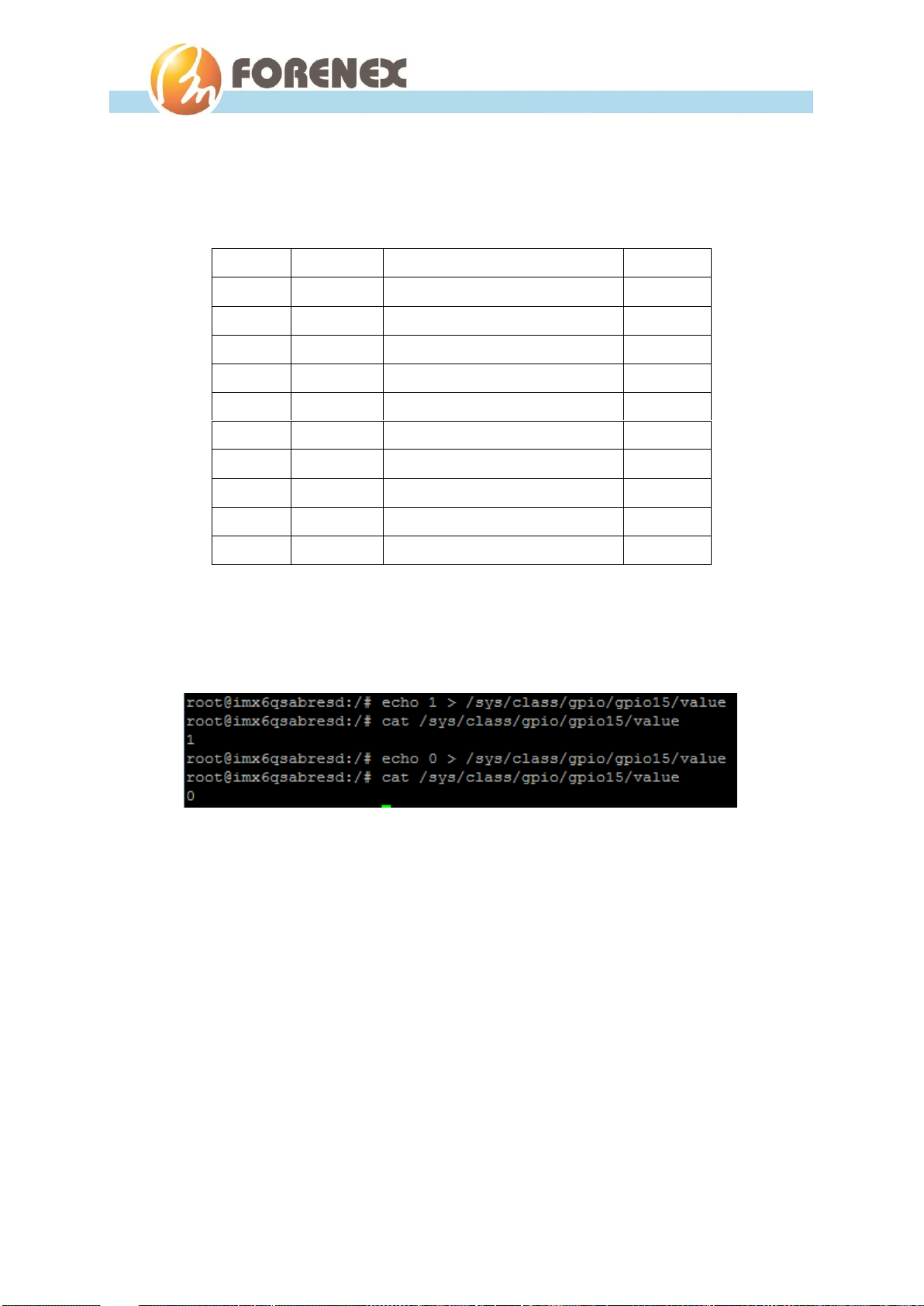
3-1-2. GPIO installation
GPIOs definition
GPIOs control method
The status of GPIOs can be set or read with the Linux command echo/cat
Debug.
Position
PIN name
Linux node/Note
Direction
PIN 7
3.3V
PIN 8
Ground
PIN 9
DOUT0
/sys/class/gpio/gpio15/value
Out
PIN 10
DIN0
/sys/class/gpio/gpio193/value
In
PIN 11
DOUT1
/sys/class/gpio/gpio14/value
Out
PIN 12
DIN1
/sys/class/gpio/gpio192/value
In
PIN 13
DOUT2
/sys/class/gpio/gpio13/value
Out
PIN 14
DIN2
/sys/class/gpio/gpio178/value
In
PIN 15
DOUT3
/sys/class/gpio/gpio12/value
Out
PIN 16
DIN3
/sys/class/gpio/gpio177/value
In
This manual suits for next models
3
Table of contents
Other Forenex Desktop manuals


