Foresight Sports SIM IN A BOX BIRDIE PACKAGE User manual

ASSEMBLY INSTRUCTIONS
VERSION 2.0BIRDIE PACKAGE
BEFORE YOU GET STARTED
ASSEMBLY INSTRUCTIONS BIRDIE PACKAGE VERSION 2.0
PAGE 2
THANK YOU for purchasing our SIM-IN-A-BOX package.
We're sure this package will provide you with years of enjoyment.
Before getting started with assembly, please conrm the following
to insure your safety and those using your simulator:
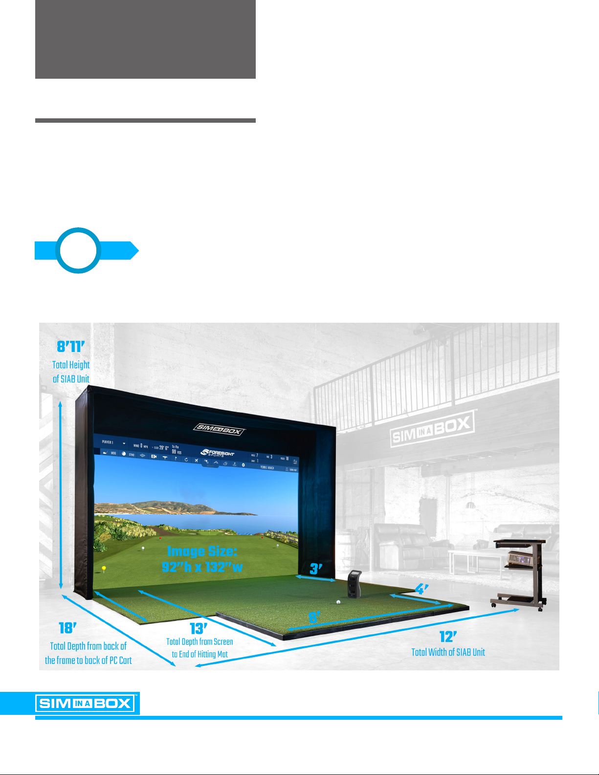
Measure and conrm you have enough space to safely install
and play. The nal setup size of your simulator will be
approximately 9 feet tall x 18 feet deep x 12 feet wide.
Make sure you have extra space for the assembly process.
1

BEFORE YOU GET STARTED
ASSEMBLY INSTRUCTIONS BIRDIE PACKAGE VERSION 2.0
PAGE 3
Following these simple guidelines will insure you get the most out of
your purchase, the safest way possible.
Make sure you have an assistant during the assembly process.
The frame assembly requires TWO PEOPLE to safely complete.
Make sure you have all required and recommended tools
(See Page 5) to insure a safe assembly and setup process.
REQUIRED FOR THIS STEP
2
3

CONTENTS INSIDE THE BOX
ASSEMBLY INSTRUCTIONS BIRDIE PACKAGE VERSION 2.0
PAGE 4
COMPONENTS
∙(1) Frame Assembly System
∙(1) Front (Hitting) Screen
∙(1) Back Screen
∙(2) Inner Walls
∙(2) Outer Wall Covers
∙(1) Lid Panel
∙(1) Above Screen Panel
∙(1) Rolling Computer Cart
∙(2) Rolls of Turf
∙(1) Hitting Mat and Tray System
∙(1) Projector with Power and HDMI Cables
∙(1) GC3 Launch Monitor
TOOLS
∙(1) Allen Wrench
∙(1) 15 Ft Steel Fish Tape (Roll)
∙(1) Zip Ties (Bundle)
∙(1) 15’ Ratcheting Rope
∙(1) Shock Cord

REQUIRED TOOLS & ITEMS
ASSEMBLY INSTRUCTIONS BIRDIE PACKAGE VERSION 2.0
PAGE 5
REQUIRED TOOLS (NOT INCLUDED)
∙(2) 6-8' Ladders
RECOMMENDED TOOLS (NOT INCLUDED)
∙Impact Drill with 3/8" Impact Adapter
∙Snips for cutting Zip Ties
∙Work Gloves
∙Eye Protection Glasses

TABLE OF CONTENTS
ASSEMBLY INSTRUCTIONS BIRDIE PACKAGE VERSION 2.0
PAGE 6
STEP 1: FRAME ASSEMBLY
STEP 2: TURF & SCREEN
STEP 3: EXTERIOR PANELS
STEP 4: COMPONENT SETUP
STEP 5: SOFTWARE SETUP
. . . . . . . . . . . . . . . . . Page 7
. . . . . . . . . . . . . . . . . Page 15
. . . . . . . . . . . . . . . . . Page 25
. . . . . . . . . . . . . . . . Page 32
. . . . . . . . . . . . . . . . . Page 41
STEP 1: FRAME ASSEMBLY
ASSEMBLY INSTRUCTIONS BIRDIE PACKAGE VERSION 2.0
PAGE 7
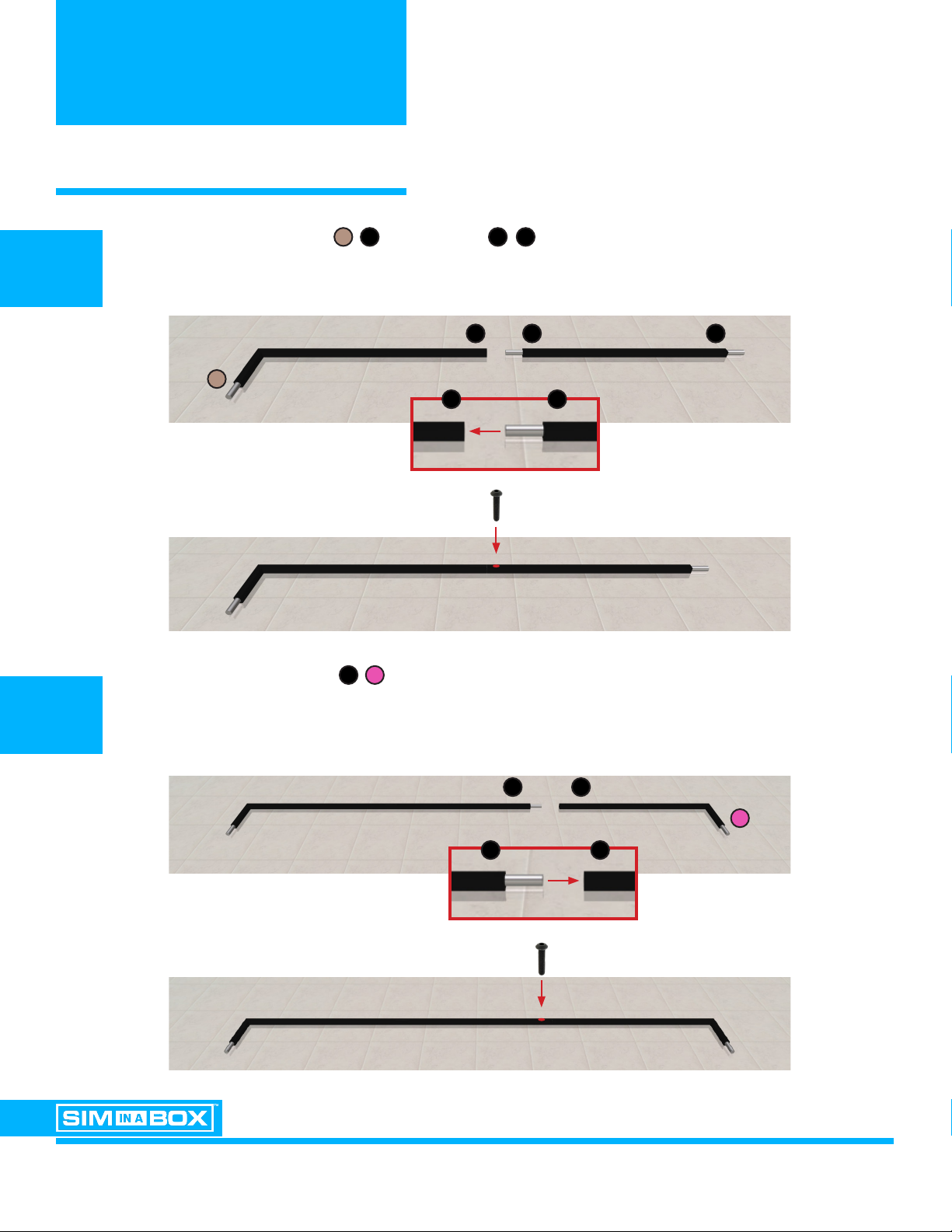
Locate the (L-Shaped) Left Base and the Center Base components. Insert the Center Base
into the Left Base as shown. Secure with 1 frame assemby screw.
Locate the (L-Shaped) Right Base component. Attach to the Base Assembly by
repeating Step 1A. Secure with 1 frame assemby screw.
1A
1B
Left Base Center Base
Right Base

STEP 1: FRAME ASSEMBLY
ASSEMBLY INSTRUCTIONS BIRDIE PACKAGE VERSION 2.0
PAGE 8
With the Base Assembly completed, locate the Left Wall Bottom and Left Wall Top
components. Connect the components as shown. Secure with 2 frame assemby screws.
2
Left Wall Top
Base Assembly
Left Wall Bottom
x 2

STEP 1: FRAME ASSEMBLY
ASSEMBLY INSTRUCTIONS BIRDIE PACKAGE VERSION 2.0
PAGE 9
Orient the Left Wall Assembly vertically as shown with the top assembly trays
facing INWARD.
3A
3B
Left Wall
Assembly
Base Assembly
Top Assembly Trays
Connect the two assemblies as shown. Secure with 1 frame assemby screw.

STEP 1: FRAME ASSEMBLY
ASSEMBLY INSTRUCTIONS BIRDIE PACKAGE VERSION 2.0
PAGE 10
Locate the Right Wall Bottom and Right Wall Top components.
Repeat Steps 3A + 3B to assemble and connect the Right Wall Assembly
4
Right Wall Bottom Right Wall Top
x 2

STEP 1: FRAME ASSEMBLY
ASSEMBLY INSTRUCTIONS BIRDIE PACKAGE VERSION 2.0
PAGE 11
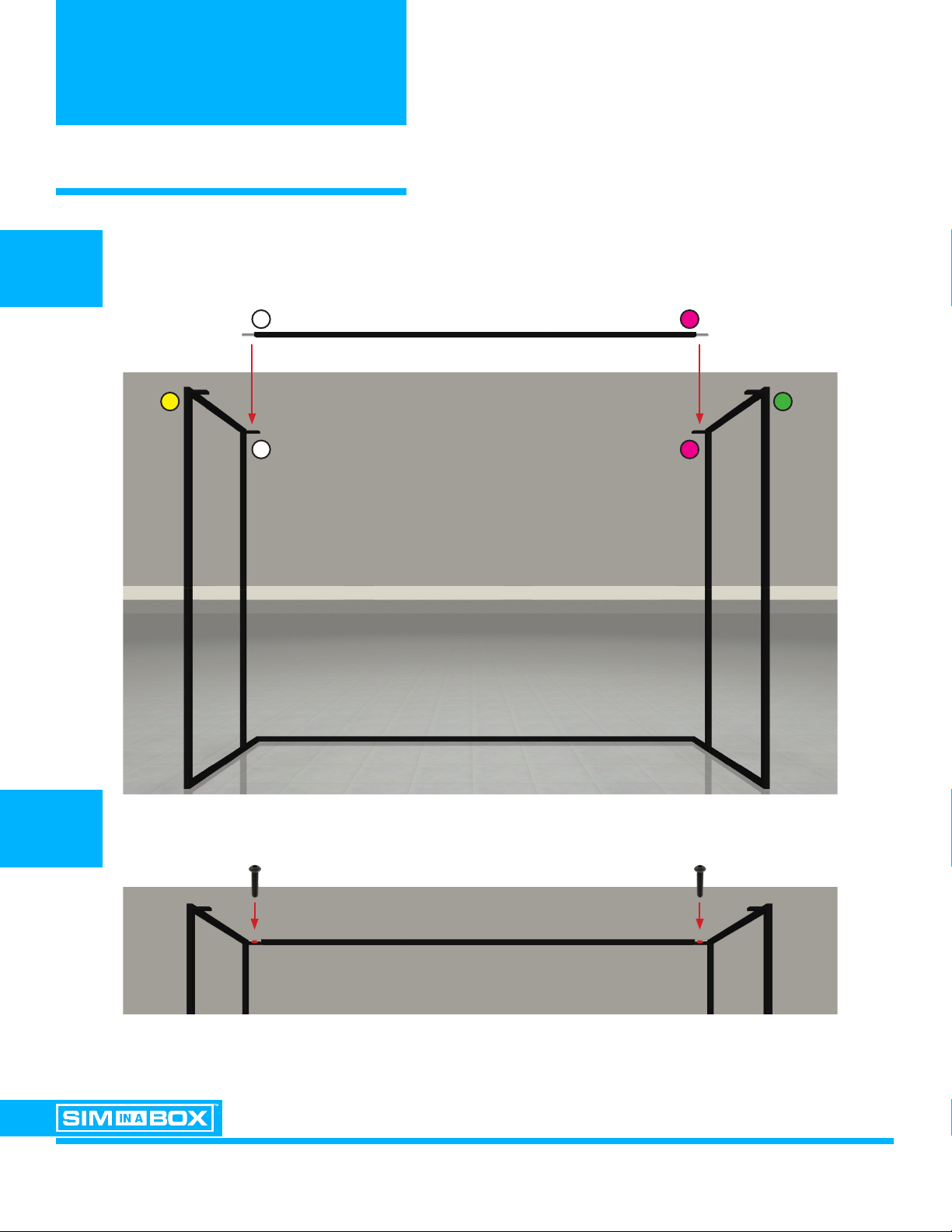
Locate the two (2) Top BACK Corner Span components and one (1) Top BACK Center Span
components. Connect the components as shown. Secure with 2 frame assemby screws.
5
Top Corner Span Top Corner SpanTop Center Span
STEP 1: FRAME ASSEMBLY
ASSEMBLY INSTRUCTIONS BIRDIE PACKAGE VERSION 2.0
PAGE 12
Using a ladder and with the help of an asssitant, carefully lower the Top Span assembly
onto the BACK Assembly Trays of the Main assembly.
Secure with 2 frame assemby screws.
6A
6B
BACK Top Span assembly
Main assembly

STEP 1: FRAME ASSEMBLY
ASSEMBLY INSTRUCTIONS BIRDIE PACKAGE VERSION 2.0
PAGE 13
Locate the two (2) Top FRONT Corner Span components and one (1) Top FRONT Center Span
Repeat Steps 5 - 6 to assemble and place the FRONT Top Span to the Main Assembly.
7
FRONT Top Span assembly
Main assembly

STEP 1: FRAME ASSEMBLY
ASSEMBLY INSTRUCTIONS BIRDIE PACKAGE VERSION 2.0
PAGE 14
Great job! The frame assembly is now complete.
DOUBLE-CHECK!
With the frame now assembled, please re-check that all
assembly bolts are tight and the frame is stable and rigid.

STEP 2: TURF & SCREEN
ASSEMBLY INSTRUCTIONS BIRDIE PACKAGE VERSION 2.0
PAGE 15
Locate the Interior Turf roll and place it inside the assembled frame.
NOTE: Make sure the assembled frame and interior turf are in their nal playing position.
1
STEP 2: TURF & SCREEN
ASSEMBLY INSTRUCTIONS BIRDIE PACKAGE VERSION 2.0
PAGE 16
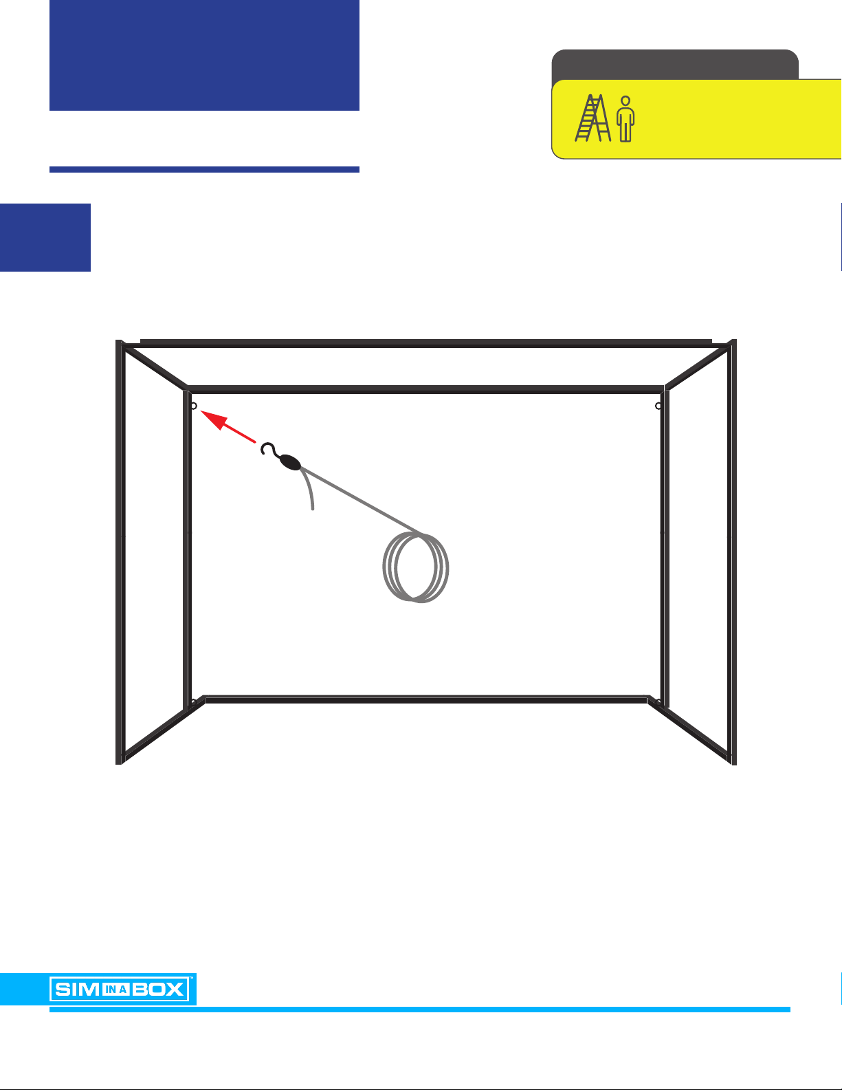
Locate the Mesh Screen Backing and the Top Attachment Cord
Attach the Top Attachment Cord to the frame by placing the hook into the steel eye hook
located on the inside top of the rear LEFT support as shown.
2
REQUIRED FOR THIS STEP
X1
STEP 2: TURF & SCREEN
ASSEMBLY INSTRUCTIONS BIRDIE PACKAGE VERSION 2.0
PAGE 17
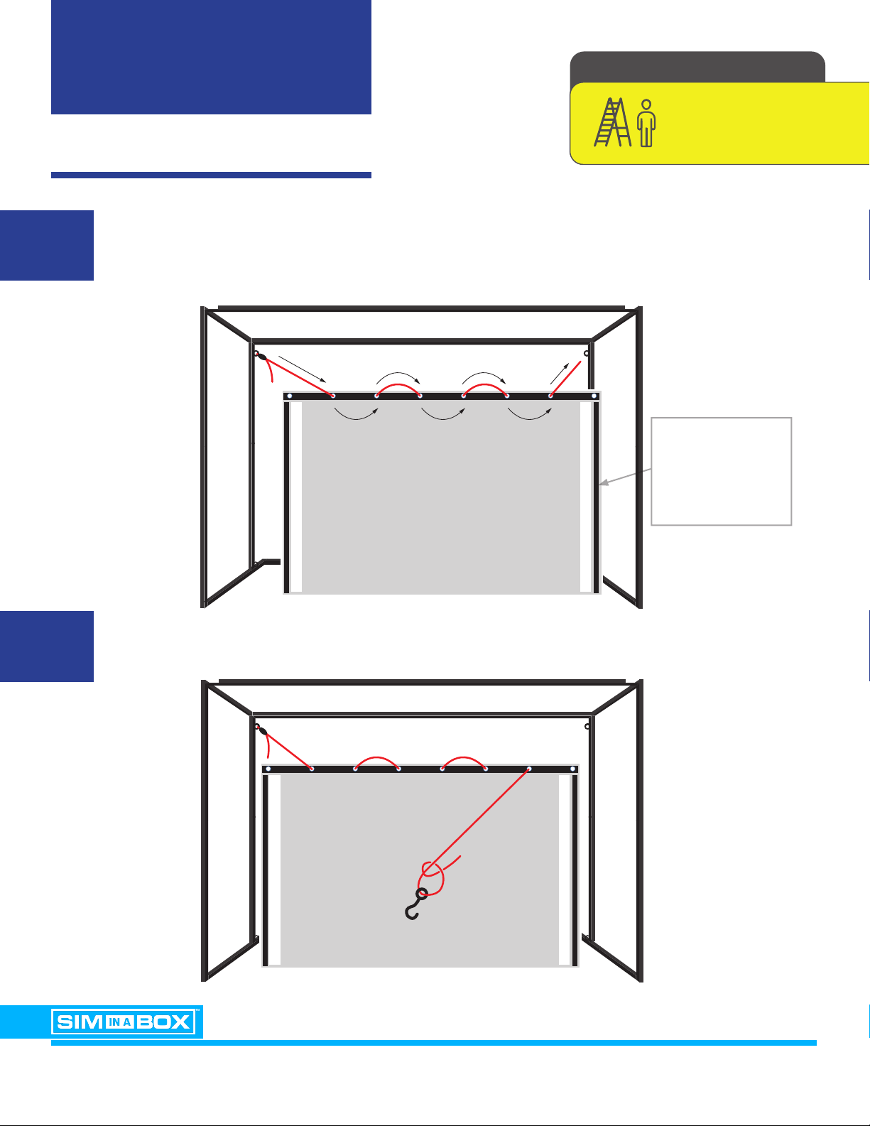
Unfold the Mesh Screen Backing and thread the Top Attachment Cord through the top row
of grommets holes STARTING WITH THE SECOND HOLE as shown. Thread the Top
Attachment Cord through all grommet holes BUT NOT the nal grommet hole.
With the Top Attachment Cord threaded, locate the separate attachment hook and tie it
onto the end. Make sure the know is propoerly tight and secure.
3A
3B
REQUIRED FOR THIS STEP
X1
Make sure the
vertical strips of
velcro are facing
forward.
STEP 2: TURF & SCREEN
ASSEMBLY INSTRUCTIONS BIRDIE PACKAGE VERSION 2.0
PAGE 18
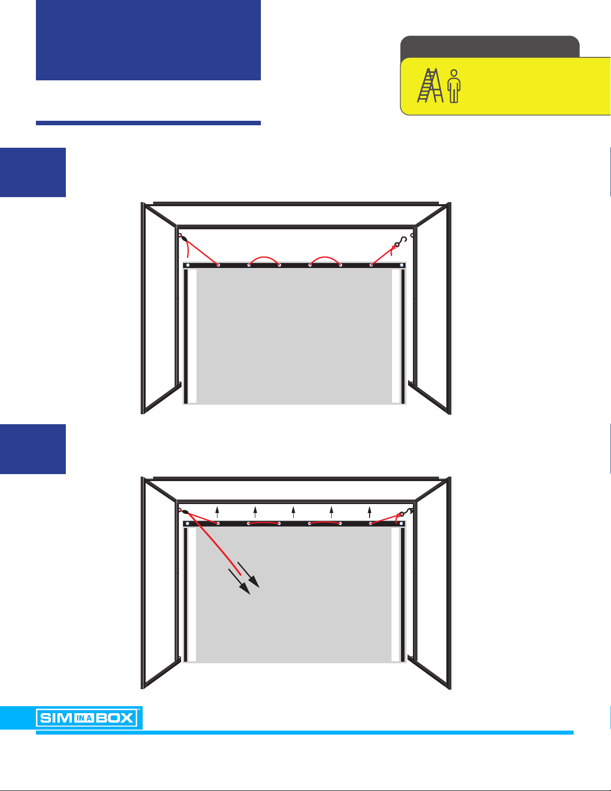
Attach the Top Attachment Cord to the frame by placing the hook into the steel eye hook
located on the inside top of the rear RIGHT support as shown.
Tighten the Top Attachment Cord by pulling on the loose end located on the left side. The
included pulley system will prevent the cord from loosening once pulled.
4A
4B
REQUIRED FOR THIS STEP
X1

STEP 2: TURF & SCREEN
ASSEMBLY INSTRUCTIONS BIRDIE PACKAGE VERSION 2.0
PAGE 19
With the Top Attachment Cord pulled tight and the Mesh Screen Backing spread out evenly,
locate the two (2) provided Zip Ties and secure the OUTER grommet holes of the Mesh
Screen Backing to the steel eye hooks holding the Top Attachment Cord on each side
of the frame.
Once attached, make sure the
two Zip Ties are secured tightly.
5A
5B
REQUIRED FOR THIS STEP
X1
STEP 2: TURF & SCREEN
ASSEMBLY INSTRUCTIONS BIRDIE PACKAGE VERSION 2.0
PAGE 20
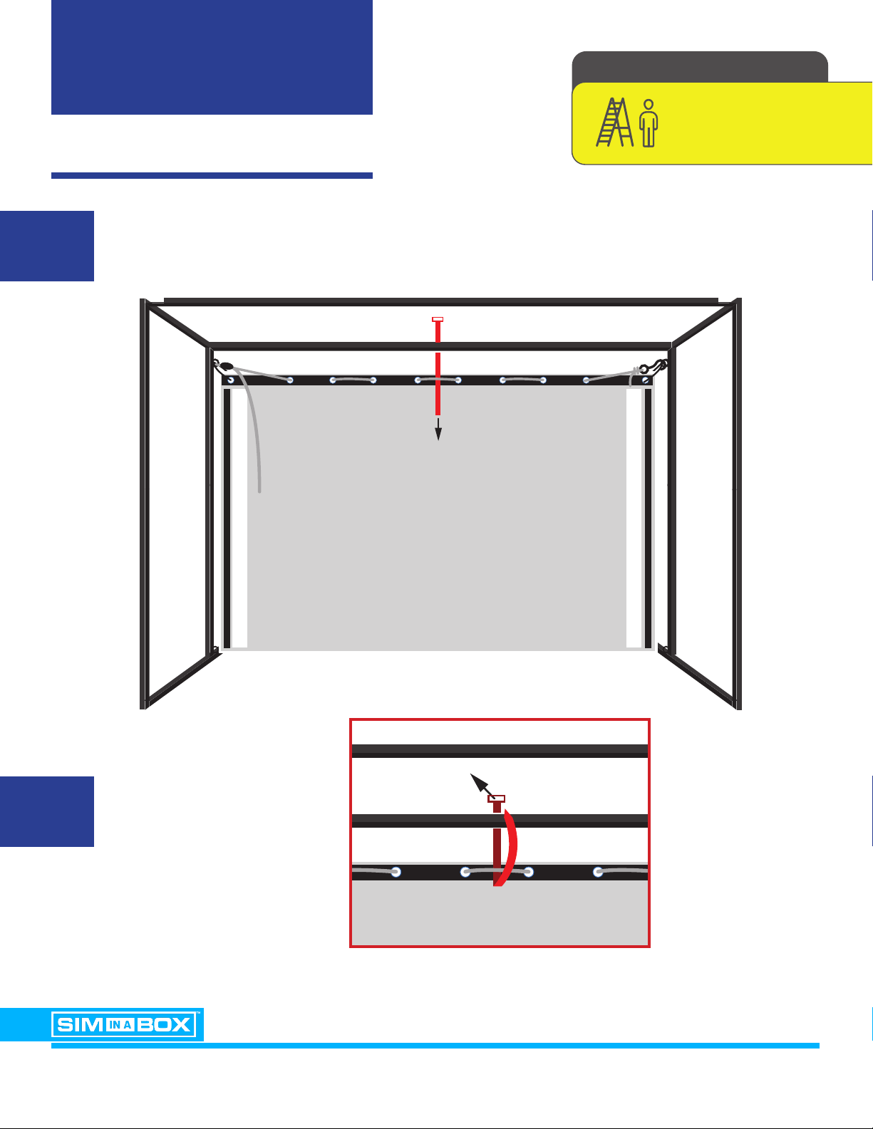
Locate the long Zip Tie provided and place it around both the center of the Rear Top Frame
Support and the Top Attachment Cord as illustrated below.
6A
6B
REQUIRED FOR THIS STEP
X1
Use to Zip Tie to raise the
Mesh Screen Backing until
it is LEVEL with both sides,
and then secure as shown.
Table of contents
Other Foresight Sports Golf Trolley manuals


