Formica Intentek Operating instructions

Formica Group Technical Guide | 1
FTB-0918 | Rev 2 | 6/20
TECHINCAL GUIDE USE & CARE, WARRANTY, AND INSTALLATON GUIDE
INTENTEK™ WIRELESS CHARGING SURFACE
TABLE OF CONTENTS
USE & CARE / SAFETY..................................................................................................................................2
Introduction: ......................................................................................................................................................................................................... 2
Intentek™System Componentry Provided by Formica Group:............................................................................................................................... 3
What is Wireless Charging: ................................................................................................................................................................................... 3
WPC, Qi and Qi Certication:................................................................................................................................................................................ 4
Incorporation of Intentek™Wireless Charging Surfaces into Furniture Design: Tips & Best Practices .................................................................... 4
To Order: 5
General Safety:..................................................................................................................................................................................................... 5
Customer Safety:.................................................................................................................................................................................................. 5
Customer Use & Care after Installation:................................................................................................................................................................. 5
Scratch and Impact Protection of the Decorative Surface: .................................................................................................................................... 5
Hot Objects: ......................................................................................................................................................................................................... 5
Ordinary Cleaning of the Decorative Surface:........................................................................................................................................................ 6
Ordinary Cleaning of Underside of Table/Counter:................................................................................................................................................. 6
FABRICATION & INSTALLATION....................................................................................................................7
Fabrication & Installation Related Safety:............................................................................................................................................................... 7
Inspection:............................................................................................................................................................................................................ 7
Storage Conditions:.............................................................................................................................................................................................. 7
Acclimation Conditions: ........................................................................................................................................................................................ 7
Fabrication Conditions:......................................................................................................................................................................................... 7
Intentek™ Wireless Charging Surfaces May Be Applied To: .................................................................................................................................. 7
Tools & Materials Sold by Formica Group:............................................................................................................................................................. 8
Additional Tools & Materials Needed: .................................................................................................................................................................... 8
Approved Adhesives:............................................................................................................................................................................................ 8
Important Installation Tips & Reminders: ............................................................................................................................................................... 9
Basic Installation Steps for Panel Lay-up and CNC Fabrication:.......................................................................................................................... 10
1. PANEL LAYUP.......................................................................................................................................................................................... 10
2. PRE-PRODUCTION – Engineering and CNC Operations .......................................................................................................................... 11
3. PRODUCTION - CNC Operations (Typical steps) ...................................................................................................................................... 12
4. PRODUCTION.......................................................................................................................................................................................... 15
5. ELECTRONICS INSTALLATION ................................................................................................................................................................ 15
6. FINISH ASSEMBLY................................................................................................................................................................................... 21
Connecting Multiple Electronics Modules to a Single AC Adapter: ...................................................................................................................... 17
Quality Check - Conrmation of Successful Installation: ...................................................................................................................................... 22
Troubleshooting:................................................................................................................................................................................................. 22
Electronics Module Unit Replacement:................................................................................................................................................................ 13
PHYSICAL PROPERTIES BACKER....................................................................................................................................22
PHYSICAL PROPERTIES LAMINATE .....................................................................................................................................23
ELECTRONICS SPECIFICATIONS & COMPLIANCE .............................................................................................................24
LIFETIME EXPECTANCY TESTING: .......................................................................................................................................25
FCC COMPLIANCE STATEMENT:...........................................................................................................................................25
UL STANDARDS:......................................................................................................................................................................26
LEGAL TERMS AND CONDITIONS OF USE ..........................................................................................................................26
WARRANTY..............................................................................................................................................................................26
Intentek™Wireless Charging Surfaces Limited Warranty:..................................................................................................................................... 26
OTHER INFORMATION:...........................................................................................................................................................29
Manufacturer: ..................................................................................................................................................................................................... 29
Electronics Disposal: .......................................................................................................................................................................................... 29
Technical Services: ............................................................................................................................................................................................. 29
Trademarks: ....................................................................................................................................................................................................... 29
Formica Group Technical Guide | 2
FTB-0918 | Rev 2 | 6/20
TECHINCAL GUIDE USE & CARE, WARRANTY, AND INSTALLATON GUIDE
INTENTEK™ WIRELESS CHARGING SURFACE
USE & CARE / SAFETY
INTRODUCTION
Intentek™Wireless Charging Surfaces feature integrated phone
charging technology within the decorative laminate surface for a
beautiful, seamless, clutter-free design and superior user experience.
• Embedded technology for an uninterrupted surface
• Fast charge times that rival cord charging
• Large 2"x2" charging zone for a simple drop and charge user
experience
• Qi Certied for safe, reliable wireless power transfer and device
protection
• Works with all Qi certied devices
• Durable laminate surface
• Easy to clean and maintain
• Full range of Formica®Brand Laminate designs
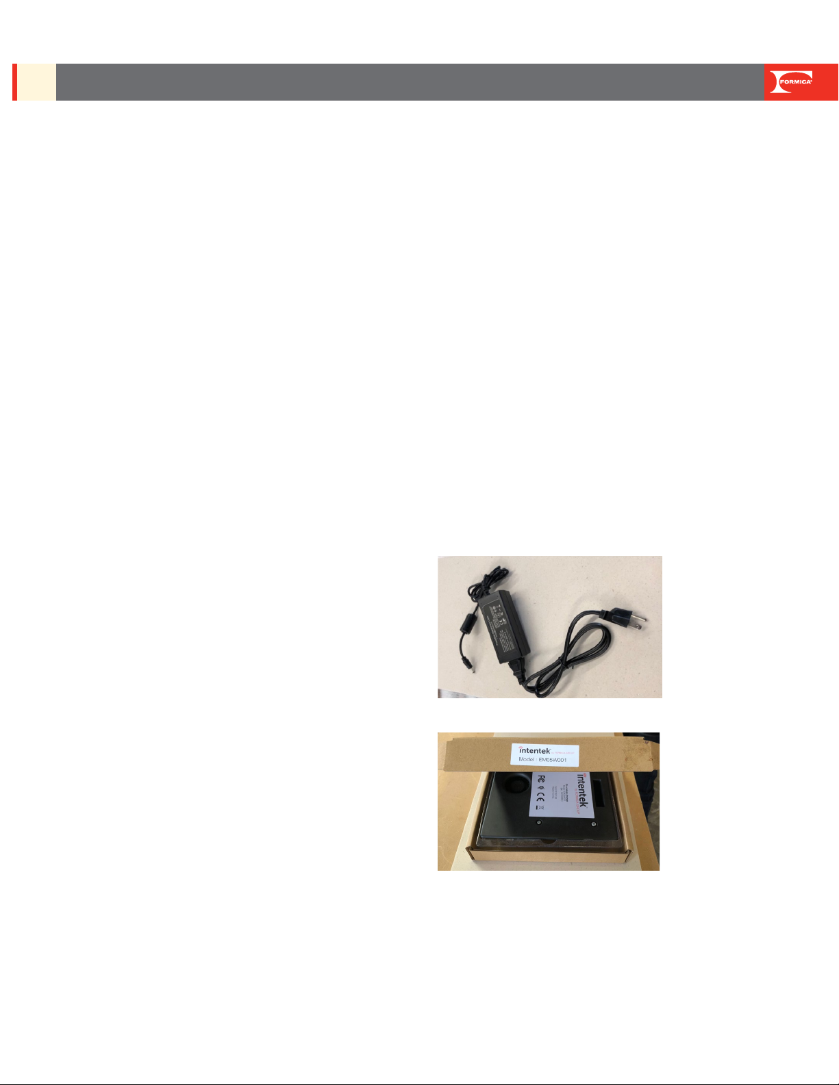
INTENTEK™ SYSTEM COMPONENTRY PROVIDED
BY FORMICA GROUP
• Intentek™Laminate
• Intentek™Laminate backer
• Intentek™Electronics universal AC power adapter
• Intentek™Electronics Module
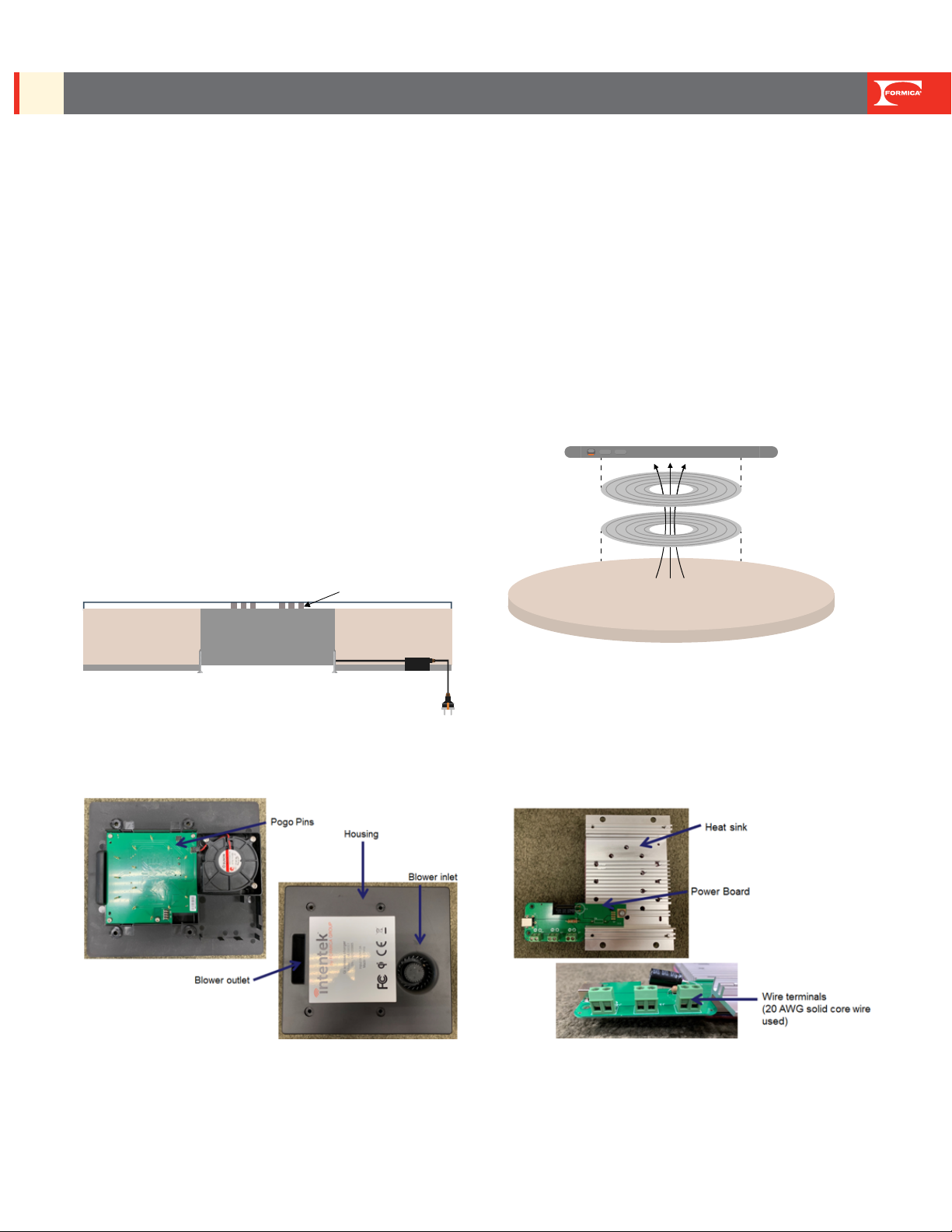
ELECTRONICS MODULE PARTS
WHAT IS WIRELESS CHARGING?
Wireless charging, also known as wireless power transfer, provides
the ability to charge a device without charging cables. The Intentek™
System uses the Qi wireless charging standard which provides safe
and reliable wireless power transfer. The power is transferred from the
Qi wireless transmitter to the Qi wireless receiver via magnetic resonant
induction. The magnetic eld is generated in the transmitter coils by a
time-varying electric current. This time-varying magnetic eld generates
an alternating electric current in the receiver coil which is rectied and
used to charge the battery.
The diagram below demonstrates this concept.
Charging Surface
Smartphone
Receiver in Smartphone
Magnetic field
Electronics
Module
Decorative Laminate
Electrical Coil Array
Substrate
Substrate
Backer
Backer
Transmitter in
Intentek™Laminate
Charging Surface
Smartphone
Receiver in Smartphone
Magnetic field
Electronics
Module
Decorative Laminate Electrical Coil Array
Substrate
Substrate
Backer
Backer
Transmitter in
Intentek™Laminate

Formica Group Technical Guide | 3
FTB-0918 | Rev 2 | 6/20
TECHINCAL GUIDE USE & CARE, WARRANTY, AND INSTALLATON GUIDE
INTENTEK™ WIRELESS CHARGING SURFACE
WPC, QI AND QI CERTIFICATION
Qi (pronounced “chee”) is the predominant standard for wireless
charging. The standard is governed by the Wireless Power
Consortium (WPC) which has more than 575 member companies. To
date, more than 500 million Qi enabled receivers have been shipped.
Qi Certied products have passed rigorous, independent laboratory
tests for safety, interoperability, energy eciency and quality. To be
certied, they must work with all Qi wireless products regardless
of brand or manufacturer. Qi certication ensures that devices (the
power receivers) and chargers (the power transmitters) always
worktogether for simple and easy charging.
INCORPORATION OF INTENTEK™WIRELESS
CHARGING SURFACES INTO FURNITURE DESIGN:
TIPS & BEST PRACTICES
Location of the charging zones will vary from project to project.
The following points represent tips and best practices that should
be considered for placement of the charging zones only. Formica
Group is not responsible and assumes no liability for the design,
engineering, installation, assembly or structural integrity of the
fabricated piece.
• Cavity for electronics module must be at least 1" from all
edges of table/top.
• Blower direction can point up, down, left, or right
(at 90°, 180°, 270°, or 360°).
• Blower inlet and outlet cannot be covered by pedestal, leg, or
other obstruction.
• When placing charging zones near each other, we recommend ..
at least 11" is left between center points of the charging icons.
The electronic module casing must be at least 1" apart.
• When placing two electronics modules near each other, a
blower inlet must be at least 8" from another blower’s outlet.
This rule is to be followed only if blower inlet and outlet are
designed to be near each other.
• If Intentek™System is going to be used in an enclosed counter
(i.e. on top of a cabinet or drawer), the enclosed space must
be properly vented. Vent determination is the responsibility
of the furniture designer. Venting must be sucient to support
the blower at 2CFM.
• Electronics module cannot be in direct contact with
obstructions: edges, screws, pedestals/legs.
TO ORDER
Call 1-800-FORMICA™or visit here: https://www.formica.com/en-
us/campaigns/intentek/intentek-inquiry-form
GENERAL SAFETY
Please read this Technical Guide, Use & Care, Warranty, and
Installation Guide and all warnings contained herein prior to handling
the Intentek™System.
CUSTOMER SAFETY
1. For indoor use only.
2. Do not overload electrical outlets.
3. AC Adapter must be plugged into a compatible mains supply to
operate.
4. Intentek™ Electronics AC Adapter or equivalent must be used.
5. Never use the AC Adapter if damaged in any way.
6. When using the AC Adapter or extension cord, conrm safety
precautions have been made so there are no tripping hazards.
7. Keep any wiring used to connect Electronics Modules covered.
CUSTOMER USE & CARE AFTER INSTALLATION
1. Do not unscrew the electronics module housing without
professional support. If internal parts are ever exposed, avoid
contact with sharp objects and moisture.
2. May not be housed outside of recommended temperature range.
3. May not be stored outdoors.
4. At all times, keep electronics module and AC adapter away from
liquids.
5. Do not place foreign or sharp objects in the electronics module
or or blower inlet/outlet.
6. Follow all cleaning instructions for decorative surface. Do not
attempt to clean inside of electronics module.
OUTLET
INLET

Formica Group Technical Guide | 4
FTB-0918 | Rev 2 | 6/20
TECHINCAL GUIDE USE & CARE, WARRANTY, AND INSTALLATON GUIDE
INTENTEK™ WIRELESS CHARGING SURFACE
SCRATCH AND IMPACT PROTECTION OF THE
DECORATIVE SURFACE
The decorative surface is resistant to scratches and impacts under
normal use and cleaning conditions. However:
• Heavy blows may crack or gouge the surface.
• Sharp or abrasive objects and unglazed ceramics materials may
slice, scratch or cause premature wear on the surface.
• Abrasive pads, scouring powders or cleaners may
permanently dull and scratch the decorative surface.
HOT OBJECTS
Hot objects, such as cookware, irons, hot appliances, cigarettes,
etc. should not be placed directly on decorative surfaces. Use a
trivet, insulated hot pad or other protective device beneath all hot
cookware, heat generated appliances or other heated objects.
Prolonged exposure to temperatures of 140°F (60°C) or higher may
cause the laminate to separate from the core material. Intentek™
Laminate surfacing material can withstand heat up to 275°F (135°C)
for short periods of time.
ORDINARY CLEANING OF THE DECORATIVE SURFACE
Decorative surface may be cleaned with a damp cloth and mild
detergent. Use of abrasive cleaners, powders, scouring pads, steel
wool, or sandpaper can damage the nish of the decorative surface.
Acid, or alkaline-based cleaners and/or compounds will mar, etch,
corrode, and permanently discolor the melamine decorative surface.
Do not use these cleaning materials on decorative laminate, nor
allow bottles and/or rags contaminated with acid or alkaline–based
cleaners/compounds to contact the surface. Accidental spills or
splatters from these harsh materials should be wiped o immediately,
and the area cleaned with a damp cloth.
Examples of cleaners containing acid, or alkali include, but are not
limited to:
• ceramic cooktop cleaners
• oven cleaners
• rust removers
• coeepot cleaners
• drain cleaners
• lime scale removers
• toilet bowl cleaners
• metal cleaners
• tub and tile cleaners
If in doubt about the suitability of a particular cleaner or detergent,
check with its manufacturer.
Additional Special Cleaning information can be found in the Formica®
Brand Laminate Use and Care Guide available on Formica.com
DISINFECTING RECOMMENDATIONS
The following branded cleaners and disinfectants are approved
for Intentek™when used according to recommended guidelines.
The products are grouped by active ingredient type. All
products on these lists meet the EPA’s criteria for use against
SARS-CoV-2, the virus that causes COVID-19. To avoid
surface damage or discoloration, wipe the surface clean to
avoid leaving disinfecting liquid open on the surface. It is also
recommended to follow disinfecting with a warm water wash
using a soft cloth and then dry the surface. Always follow the
manufacturers’ guidelines and safety precautions for these
products.
For EPA updates on the current List N and Frequently
Asked Questions about disinfectants related to coronavirus
visit:
https://www.epa.gov/pesticide-registration/list-n-disinfectants-
use-against-sars-cov-2
QUATERNARY AMMONIUM
Clorox®Disinfecting Wipes
Clorox Healthcare®VersaSure®Wipes
Lysol®Brand All Purpose Cleaner
Lysol®Kitchen Pro Antibacterial Cleaner
Virex™II
Fantastik®Multi-Surface Disinfectant Degreaser
Maquats®
QUATERNARY AMMONIUM: ISOPROPANOL
Super Sani-Cloth®Germicidal Disposable Wipe
Cavicide™Wipes
Sani-Prime®Germicidal Spray
Opti-Cide3®Wipes
ISOPROPANOL, IPA, RUBBING ALCOHOL,
SODIUM HYPOCHLORITE (BLEACH)
Clorox Healthcare®Bleach Germicidal Wipes
Clorox®Brand Regular Bleach
Sani-Cloth®Bleach Germicidal Wipe
Caviwipes™Bleach
Dispatch®
Lysol®Brand Bleach Mold/Mildew Remover
All related brands containing bleach
HYDROGEN PEROXIDE
Clorox®Commercial Solutions®Hydrogen Peroxide Disinfectant
and wipes
Formica Group Technical Guide | 5
FTB-0918 | Rev 2 | 6/20
TECHINCAL GUIDE USE & CARE, WARRANTY, AND INSTALLATON GUIDE
INTENTEK™ WIRELESS CHARGING SURFACE
Oxivir™Tb and wipes
Accel®TB and wipes
Peroxide Multi Surface Cleaner and Disinfectant
Suretouch®
Oxy-Team™Disinfectant Cleaner
ORDINARY CLEANING OF UNDERSIDE OF TABLE/
COUNTER
Should cleaning on the underside of the counter/table be needed,
avoid exposing the electronics to any liquids.
FABRICATION & INSTALLATION
FABRICATION & INSTALLATION RELATED SAFETY
1. All points in Customer Safety above also pertain to fabrication
and installation safety.
2. Fabricators and installers must follow all OSHA/ National Electric
Code /UL Standards as required by installation location or
customer.
3. Do not power the electronics until fully assembled into a table or
top. Make all connections to the Intentek™Electronics Module
before applying power.
4. Intentek™ Electronics AC Adapter or equivalent must be used.
Formica Group does not recommend or warranty hardwiring.
5. Do not install nished table or top while electronics are powered.
6. Always use recommended wire to connect electronics modules.
7. Always cover wiring underneath table/counter.
INSPECTION
Inspect all materials at the time they are received to ensure all
components are free of damage and/or visible defects. Do not
assemble materials with known defects. It is the responsibility of the
customer/fabricator/installer to inspect materials before installation.
Before fabrication, conrm that Computer-Aided Design (CAD) les
are available.
STORAGE CONDITIONS
The optimal conditions for storage are 50 – 90°F (10 – 32°C) and
30% – 65% humidity. Keep materials free from moisture, dust, and
impact. The material should never be stored in contact with the oor
or an outside wall.
Laminate sheets and backers have been shipped in a way to protect
both materials. Formica Group recommends that they are stored
in the way they are shipped in order to continue to protect until
installation.
Due to delicate nature of the coils embedded in the underside of the
decorative laminate, do not slide the back of the laminate against
another surface. Keep coils covered with the provided
covering until cavity has been cut with CNC.
ACCLIMATION CONDITIONS
Prior to fabrication, allow laminate sheet, backer, and substrate to
acclimate for at least 48 hours at the same ambient conditions. The
optimal conditions for acclimation are 50 – 90°F (10 – 32°C) and
30% – 65% humidity.
FABRICATION CONDITIONS
Laminate sheets, backers, substrate surfaces, and electronic
components must be dry, clean and free of all grease, dust, and
foreign matter. The optimal conditions for fabrication are
50 – 90°F (10 – 32°C) and 30% – 65% humidity.
INTENTEK™WIRELESS CHARGING SURFACES MAY BE
APPLIED TO
1. Medium Density Fiberboard (MDF)
2. Particleboard
3. Hardwood Faced Veneer Core Plywood, also known as
Grade A Faced Plywood
TOOLS & MATERIALS SOLD
BY FORMICA GROUP
• Intentek™ Laminate in the specied quantity
• Intentek™ Laminate backer in the specied quantity
• Intentek™Electronics Universal AC power adapter in the
specied quantity
• Intentek™ Electronics module in the specied quantity
• Test Receiver {Provided to Fabricator Partners Only}
• Test Receiver manual {Provided to Fabricator Partners Only}
ADDITIONAL TOOLS & MATERIALS NEEDED
• Personal Protective Equipment (PPE), examples:
• Eye protection
• Dust mask
• Gloves
• Hearing protection as needed
Formica Group Technical Guide | 6
FTB-0918 | Rev 2 | 6/20
TECHINCAL GUIDE USE & CARE, WARRANTY, AND INSTALLATON GUIDE
INTENTEK™ WIRELESS CHARGING SURFACE
• Approved substrate that is at least ¾" thick
• Panel layup equipment
• Approved adhesives - Polyvinyl acetate (PVA), Polyurethane
(PUR), Contact Adhesives
• CNC machine
• CAD program for CNC machine
• Phillips head screwdriver
• A table or work surface
• Depth gauge
• Cleaning cloths
• Cleaner (as recommended by adhesive manufacturer to remove
any dried adhesive)
APPROVED ADHESIVES
Polyvinyl acetate (PVA), Polyurethane (PUR), Contact Adhesive
IF MULTIPLE ELECTRONICS MODULES ARE TO BE
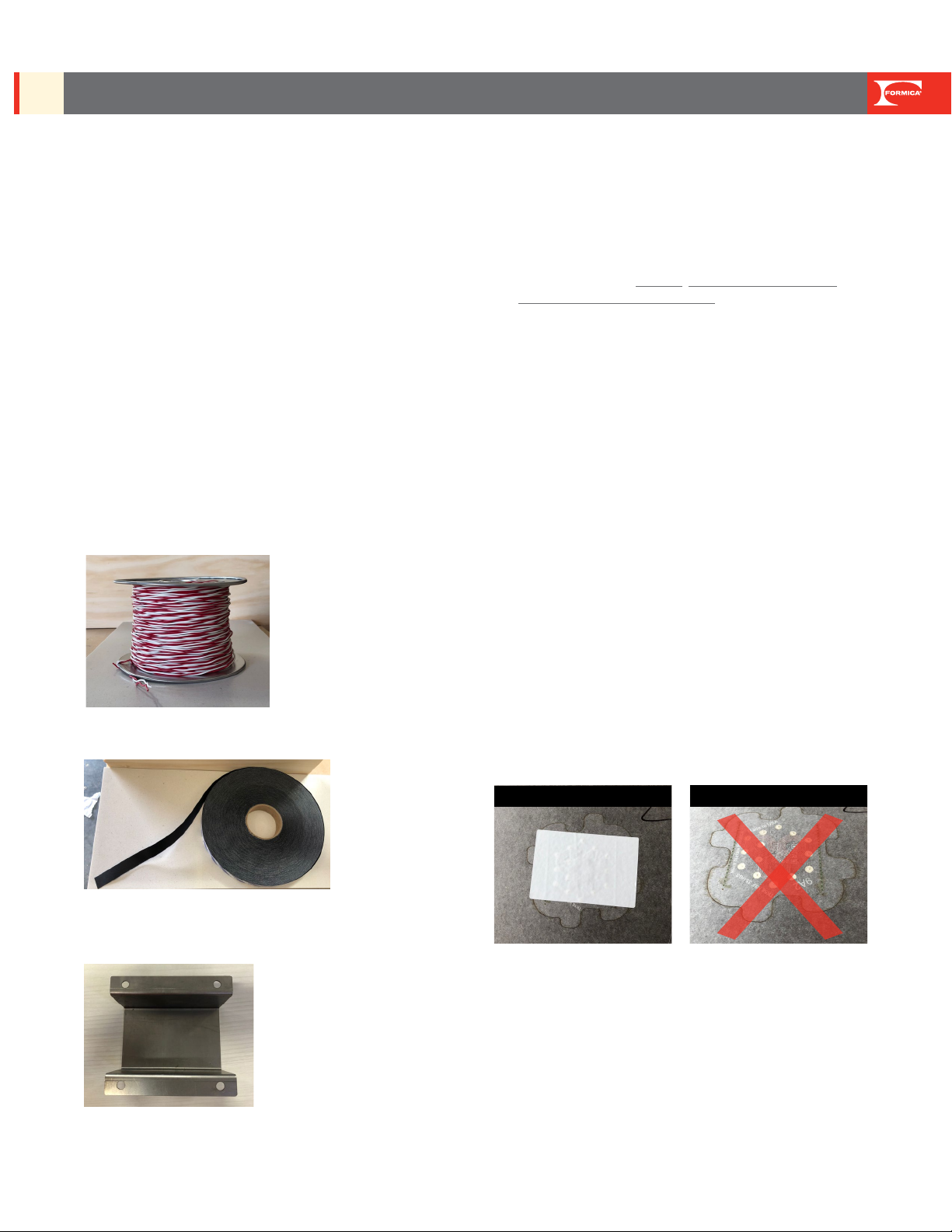
CONNECTED, ADDITIONAL TOOLS
• Wire cutter
• Wire stripper
• Small slotted screwdriver
• Two colors of 20 AWG solid core wire or thicker
• Sheathing coverage for wire channels
• 3" alignment screws as needed
• Cradle for AC/DC converter box with screws as needed (to hold
adapter under top)
• Alternative length AC Adapter or extension cord as needed
• Edge bander or other method to nish table/counter edging
as needed
• Table/counter base as needed
IMPORTANT INSTALLATION TIPS & REMINDERS
• For fabrication techniques specic to working with High Pressure
Laminate, refer to the Formica®Technical and Installation
Guide for High Pressure Laminate.
• Material, equipment, and workmanship should conform to the
Formica Group recommended standard practices, conditions,
procedures, and recommendations as specied by ANSI/NEMA
LD3-2005, Architectural Woodwork Quality Standards and ANSI
A161.2-1998 Standards.
• Fabricating with peel coat on surface is recommended.
• Router base should be clean and free of burrs and debris. All
work surfaces should be clean, at, and free of burrs. Conrm
laminate, backer, and substrate are dry, clean and free of all
grease, dust, and foreign matter.
• Before beginning, conrm storage, acclimation and fabrication
conditions outlined above have been met.
BASIC INSTALLATION STEPS FOR PANEL
LAY-UP AND CNC FABRICATION
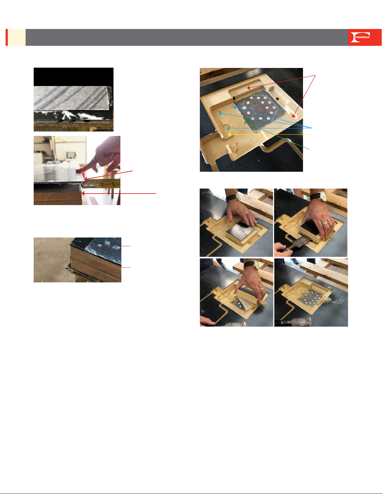
1. PANEL LAY-UP
1A) SUBSTRATE: Use industrial substrate suitable for HPL (high
pressure laminate) bonding.
1B) CLEAN: All surfaces of all materials including substrate,
Intentek™Laminate sheet and backing sheet to remove any debris
which would cause telegraphing. Do not remove the 5"x5" masking
from charging zones on the back of the Intentek™Laminate face
sheet. If 5"x5" masking has been removed accidently, add masking
tape, that does not have too much tack, over contact pads before
proceeding.
1C) ADHESIVE: Apply adhesive to the substrate per adhesive
manufacturer instructions for bonding HPL (high pressure laminate). It
is advised that a test is done to assure bond.
1D) INTENTEK™LAMINATE FACE SHEET INDEXING: Using the
marked reference edge, position face sheet with a consistent ¼"
(0.25") overhang on the substrate length and consistent ¼" (0.25")
overhang on the substrate width. NOTE: Face sheet must extend
beyond the substrate and backer edge to maintain the reference
edge for the CNC operation.
Keep 6'x6' Masking in Place Do Not Layup Panel without Masking
*Corded/stranded wire is not recommended
Formica Group Technical Guide | 7
FTB-0918 | Rev 2 | 6/20
TECHINCAL GUIDE USE & CARE, WARRANTY, AND INSTALLATON GUIDE
INTENTEK™ WIRELESS CHARGING SURFACE
1E) INTENTEK™LAMINATE BACKER SHEET INDEXING:
Position backer sheet aligned to the substrate board edge. Backer
must be aligned to the substrate edge and not overhang.
1F) PROCESS OF BONDING: A heat tunnel with heated or cold nip
rollers can be used or a conventional hot or cold press. Regardless
of the process, the face sheet indexing above must be maintained as
specied.
2. PRE-PRODUCTION: ENGINEERING & CNC OPERATIONS
2A) ENGINEERING: Load cut le for the job into the CNC for
cutting. Set machine to remove entire cavity for checking depth
measurement.
2B) TEST MACHINING: It is recommended that a test piece of core
is run, measured and dry tted to ensure proper machining and t
before processing.
2C) IMPORTANT PARTS OF CAVITY:
a. Flange for heat sink (measured from top of ange to bottom of
cavity where contract pads are, which is 13.31mm or .524 inch)
b. Blower screws recess area
c. Power board support ange
d. Structural support of area with exception of area cut out for
contact pads
2D) CAVITY PERIMETER CUT:
a. Formica Group requires using a perimeter cut for the contact
pad area. MDF/Particleboard/Plywood will be removed after CNC
cut is complete. For this perimeter cut, we recommend to use
1/4" or 3/8" bit.
2E) BOTTOM/UP CNC PROGRAMMING: Formica Group
understands that CNC programs dier. Formica Group will supply
CAD les that will have bottom/up measurements of the cavity. Our
recommendation is to cut cavity using a bottom/up measurement
from the vacuum table. By doing this, CNC machine will reference
and cut to the deepest measurement of cavity, which is 2.3mm
(which will cut to the very back of the Intentek™decorative face
sheet). If CNC programming requires top/down measurements,
fabricator will need to adjust CNC Cut le.
2F) OPTIONAL CONFIRMATOIN OF MEASURMENTS: Prior
to fabrication, should fabricator want to conrm that laminate
measurements match the CNC Cut le, do not measure from the
decorative side where the charging icon is placed. Center point
measurements can be made from backside of laminate as shown
below.
B. Screw Recess
A. Flange
C. Powerboard Support
D. Structural Support
Decorative sheet of
Intentek™laminate is
overhanging the substrate.
Substrate
Example of marked reference edge.
Reference edge also marked on
decorative side with label.
Backer should be ush
with the substrate
Decorative Face Sheet
overhangs substrate.

Formica Group Technical Guide | 8
FTB-0918 | Rev 2 | 6/20
TECHINCAL GUIDE USE & CARE, WARRANTY, AND INSTALLATON GUIDE
INTENTEK™ WIRELESS CHARGING SURFACE
CAUTION: When measuring, do not use any tools that could
damage the contact pad.
NOTE: The end with the double layer of contact pads is where the
electronics blower oulet will be.
3. PRODUCTION: CNC OPERATIONS (TYPICAL STEPS)
3A) RESET CNC: Reset CNC program for cutting to do a perimeter
cut of the deepest part of cavity (the part where the contact pads are
exposed). We do not recommend removal of material within this area
until after CNC operation is complete.
3B) POSITION BOARD: Position the decorative laminate side of
panel face down on the CNC table.
3C) ALIGN BOARD: Position the decorative laminate side of Align
reference edge of panel decorative laminate sheet to the CNC
alignment pins on the vacuum table prior to initiating the cutting
operation.
3D) WARNING: Machining must not contact the charging zone area
contact pads which will impact/defeat the performance of the end
product.
3E) RUN CNC: Run CNC program to make all cuts into the
substrate, which may include:
a. the electronics cavity or cavities into the substrate
b. wire or adapter tracks
c. attachment holes for table legs
3F) REMOVE CAVITY PIECE: When job is complete, remove cavity
substrate piece (that was created with the perimeter cut) from the
cavity to reveal the contact pads. At this time, the 5"x5" masking
should also be removed.
3G) CONFIRM CAVITY MEASUREMENT: Check to conrm the
distance from the ange where the heat sink will eventually be
screwed in to the bottom of the cavity where the contact pads are.
This measurement should be 13.31 mm. (.524 inch)
This end is where
blower outlet will
be orientented
This is where the center
point is measured

Formica Group Technical Guide | 9
FTB-0918 | Rev 2 | 6/20
TECHINCAL GUIDE USE & CARE, WARRANTY, AND INSTALLATON GUIDE
INTENTEK™ WIRELESS CHARGING SURFACE
3H) CONFIRM FIT: Test t of heat sink to the cavity by placing into
the cavity. Heat sink should not rock side-to-side, but sit evenly
in the cavity. Check to conrm the silver contact pads are visible
through the holes in the heat sink.
4. PRODUCTION
4A) COMPLETE EDGING AS NEEDED: Table or counter should be
edged as specied.
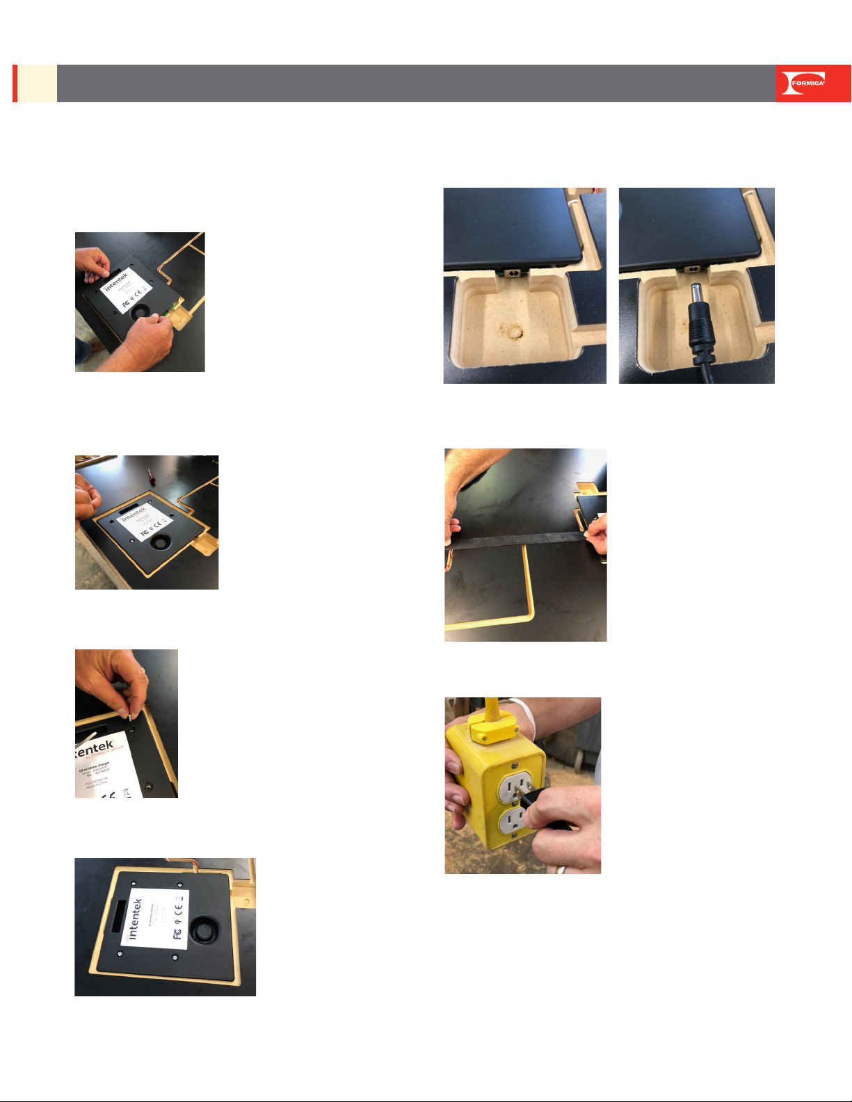
5. ELECTRONICS INSTALLATION
5A) UNSCREW MODULE: Unscrew electronic module from heat
sink cover. Retain screws for nal assembly.
5B) PEEL BLUE COAT: Peel o blue peel coat from the gap pad.
Take care not to pull o the gray gap pad.
5C) ALIGN HEAT SINK: Align the heat sink in the cavity by visually
centering the heat sink holes on all of the silver contact pads.
5D) PLACE 1ST SCREW IN HEAT SINK: Press the heat sink down
and place initial screw - check to conrm all contact pads are still
visible through the holes in the heat sink.
5E) SCREW IN HEAT SINK: Place the remaining three screws into
heat sink and tighten. CAUTION: Do not overtighten screws in the
substrate.
5F) CONNECT MULTIPLE CHARGING ZONES AS NEEDED: If
design calls for multiple electronics zones to be connected, follow
instructions now that are found in the box on the next page. If you
are only installing one charge zone, skip to step 5G.
Wiring should be done before electronics module housing is
attached in next step.
Heat shink should not
rock from side-to-side
Make sure all contact
pads are visbile
Formica Group Technical Guide | 10
FTB-0918 | Rev 2 | 6/20
TECHINCAL GUIDE USE & CARE, WARRANTY, AND INSTALLATON GUIDE
INTENTEK™ WIRELESS CHARGING SURFACE
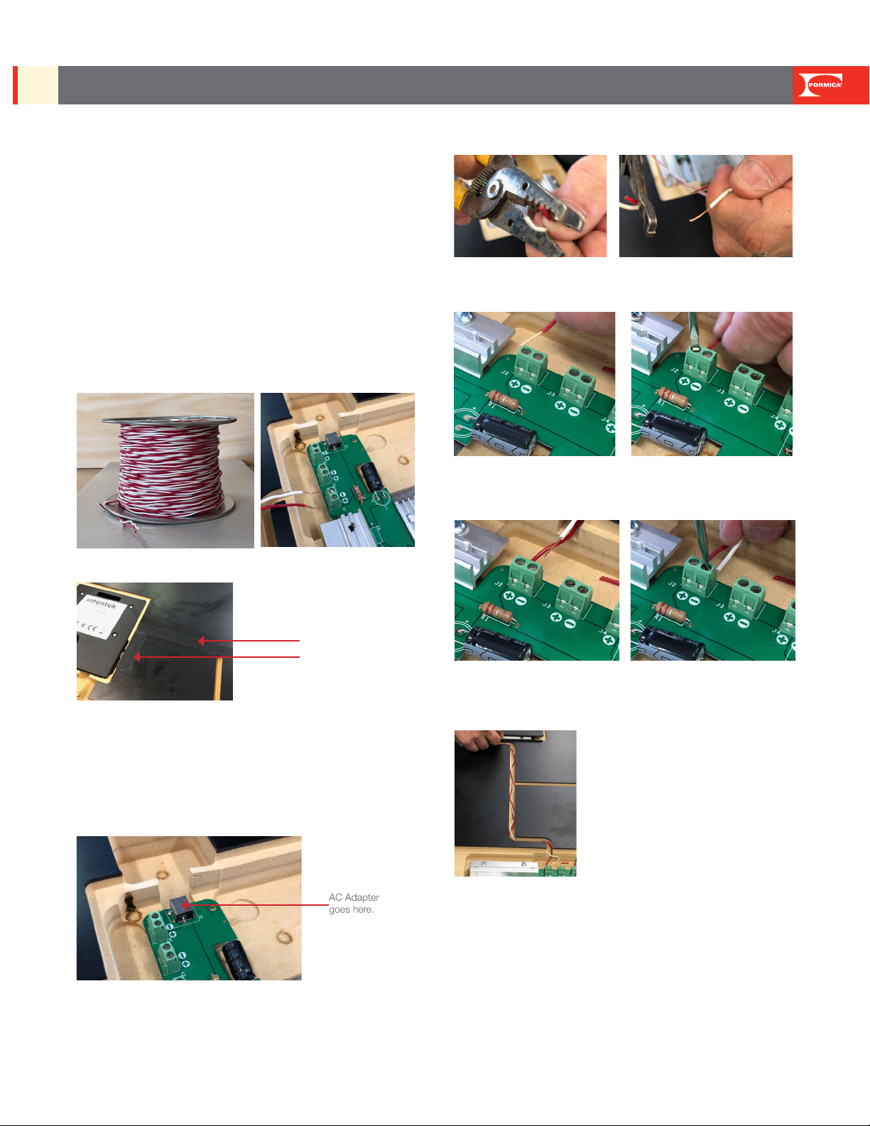
CONNECTING MULTIPLE ELECTRONICS MODULES TO
A SINGLE AC ADAPTER
REMINDERS:
• Up to four electronics modules can be connected with a single
power source. Use this step if the design requires multiple
electronics modules to be connected.
• 20 AWG corded wire is the minimum gauge required.
• When connecting multiple electronics units together, it is critical that
instructions are followed. The correct polarity is important, or the
electronics will not operate.
• Always use two cord colors. Formica Group recommends using a
red wire for positive and a white wire for negative.
• Always cover wire when top is nished.
• Never work with electrical wiring while powered.
INSTRUCTIONS FOR CONNECTING MULTIPLE
CHARGING ZONES TOGETHER
a) Conrm electronics are not plugged into a power source.
b) Locate the parent electronics module (the parent is the one that
will be plugged into the AC Adapter).
c) Using a wire stripper, strip 3/16" o one end of the red and white
wires to expose the wire underneath.
d) Using a small slotted screwdriver, tighten the exposed wire of
the positive (red) wire into the positive port in the parent’s power
distribution board.
e) Using a small slotted screwdriver, tighten the exposed wire of the
negative (white) wire into the negative port in the parent’s power
distribution board.
f) Measure the length of wire needed to reach the next electronics
module and cut. Strip this end to expose 3/16" of both red and
white cords.
g) Using a small slotted screwdriver, tighten the exposed wire of
the positive (red) wire into the positive port in the second power
distribution board.
h) Using a small slotted screwdriver, tighten the exposed wire of the
negative (white) wire into the negative port in the second power
distribution board.
i) Repeat until all of electronics modules have been connected.
j) Check to be certain all wires are tight in terminal strips.
Sheathing coverage
for wire channels
Formica Group Technical Guide | 11
FTB-0918 | Rev 2 | 6/20
TECHINCAL GUIDE USE & CARE, WARRANTY, AND INSTALLATON GUIDE
INTENTEK™ WIRELESS CHARGING SURFACE
5. ELECTRONICS INSTALLATION (CONTINUED)
5G) ALIGN ELECTRONICS HOUSING: Visually align the screw
holes in the electronics housing over the holes in the heat sink and
use as a guide when dropping in the housing. Be careful not to stress
pogo pins.
3" screws can be used to help with alignment. Thread 3" alignment
screws into housing system in opposite corners to use as guides to
drop housing system in. This will help protect pogo pins. Remove
alignment screws before proceeding to next step.
5H) ATTACH ELECTRONICS HOUSING: Press and attach
electronics module housing to heat sink.
5I) SCREW IN HOUSING: Use four screws to secure housing to
heat sink.
5J) CONNECT ADAPTER: Connect AC Adapter into the master
module.
5K) COVER WIRES AS NEEDED: Place protective sheathing cover
over exposed wires as needed.
5L) PLUG IN: Plug AC Adapter into a compatible mains outlet
5M) CONFIRM CORRECT INSTALLATION: Complete quality
check (see below)
6. FINISH ASSEMBLY
6A) FINISH FURNITURE BASE: Install support leg(s) per the
component design
Formica Group Technical Guide | 12
FTB-0918 | Rev 2 | 6/20
TECHINCAL GUIDE USE & CARE, WARRANTY, AND INSTALLATON GUIDE
INTENTEK™ WIRELESS CHARGING SURFACE
QUALITY CHECK - CONFIRMATION OF
SUCCESSFUL INSTALLATION
Trained Formica®Fabricator Partners will receive a Test Receiver
to conrm that the electronics are working upon completion of
fabrication. Fabricator Partners should refer to test procedure in Test
Receiver manual.
If an electronics module is ever re-installed, it must be recalibrated for
Foreign Object Detection. Call 1-800-FORMICA™or reference Test
Receiver Manual for this procedure.
TROUBLESHOOTING
If the system does not appear to be charging, power down by
unplugging, wait ve seconds, and plug back in. If you do not hear
a beep when reconnecting, check all plug connections to conrm
complete connections.
If this does not work, call 1-800-FORMICA™.
ELECTRONICS MODULE UNIT REPLACEMENT
Call 1-800-FORMICA™.
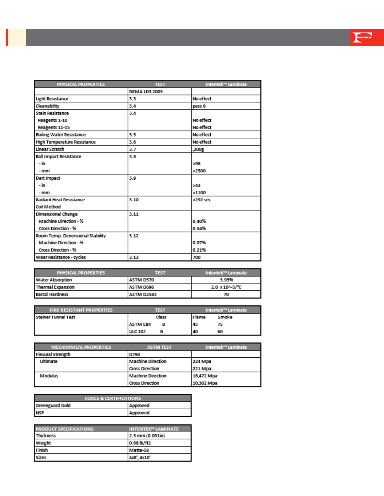
PHYSICAL PROPERTIES OF INTENTEK™LAMINATE BACKERS
Formica Group Technical Guide | 13
FTB-0918 | Rev 2 | 6/20
TECHINCAL GUIDE USE & CARE, WARRANTY, AND INSTALLATON GUIDE
INTENTEK™ WIRELESS CHARGING SURFACE
PHYSICAL PROPERTIES OF INTENTEK™LAMINATE BACKERS
Formica Group Technical Guide | 14
FTB-0918 | Rev 2 | 6/20
TECHINCAL GUIDE USE & CARE, WARRANTY, AND INSTALLATON GUIDE
INTENTEK™ WIRELESS CHARGING SURFACE
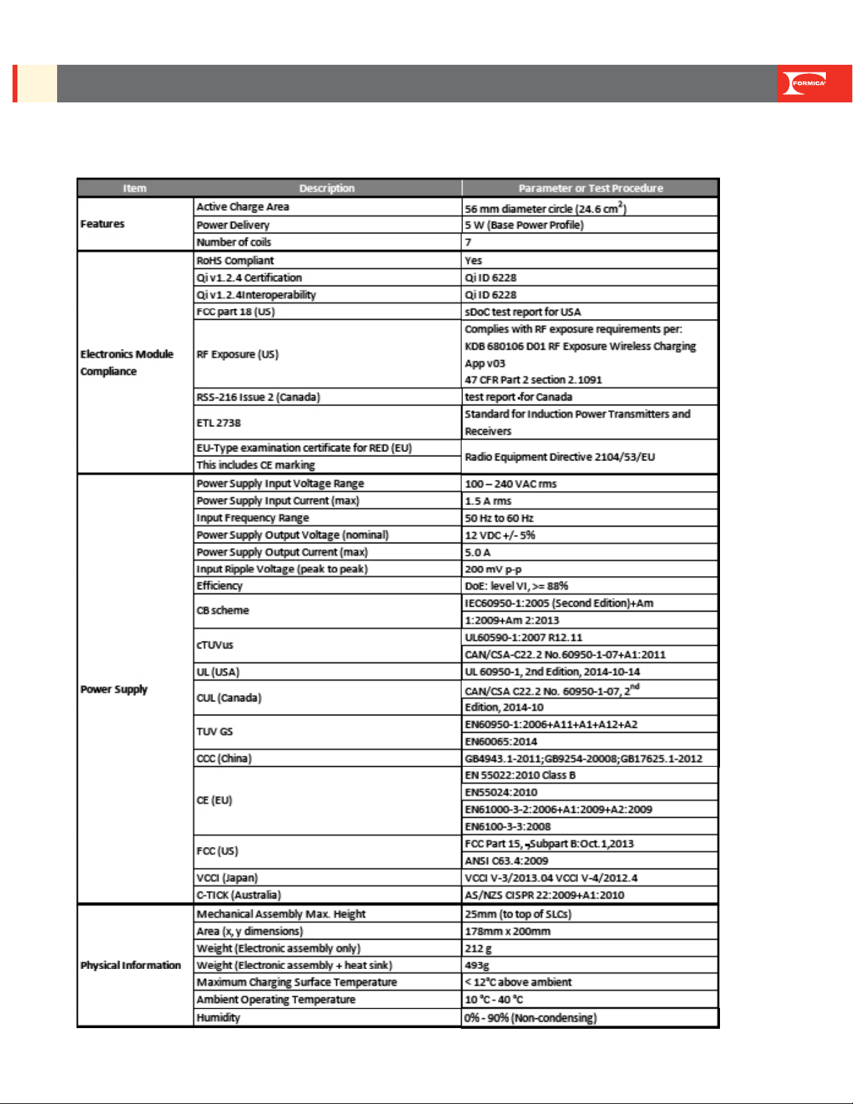
ELECTRONIC MODULE AND AC ADAPTER SPECIFICATIONS AND COMPLIANCE

Formica Group Technical Guide | 15
FTB-0918 | Rev 2 | 6/20
TECHINCAL GUIDE USE & CARE, WARRANTY, AND INSTALLATON GUIDE
INTENTEK™ WIRELESS CHARGING SURFACE
LIFETIME EXPECTANCY TESTING
The electronic module has undergone accelerated life testing to
simulate seven years of continuous use. Lifetime Expectancy is not
equivalent to warranty. See Warranty Section within this guide for
additional details.
FCC COMPLIANCE STATEMENT
This device complies with Part 18 of the FCC Rules Warning:
Changes or modications to this unit not expressly approved by the
party responsible for the compliance could void the user’s authority
to operate the equipment. Note: This equipment has been tested
and found to comply with the limits for ISM equipment, pursuant
to Part 18 of the FCC Rules. These limits are designed to provide
reasonable protection against harmful interference in a residential/
commercial installation. This equipment generates, uses, and can
radiate radio frequency energy and, if not installed and used in
accordance with the instructions, may cause harmful interference
to radio communications. However, there is no guarantee that
interference will not occur in a particular installation. If this equipment
does cause harmful interference to radio or television reception,
which can be determined by turning the equipment o and on, the
user is encouraged to try to correct the interference by one or more
of the following measures:
• Reorient or relocate the receiving antenna.
• Increase the separation between the equipment and receiver.
• Connect the equipment into an outlet on a circuit dierent from
that to which the receiver is connected.
• Consult the dealer or and experienced radio/TV technician for
help.
The user is cautioned that changes and modications made to the
equipment without the approval of manufacturer could void the user’s
authority to operate this equipment.
• The operating Frequency band(s): 111.920kHz
• “Hereby, Formica Group declares that the radio equipment type
Wireless Power Charge is in compliance with Directive
2014/53/EU. The full text of the EU declaration of conformity
is available at the following URL:
https://eur-lex.europa.eu/legal-content/EN/TXT/?uri=CELEX:32014L0053
• No restriction for EU countries.
• This equipment complies with radiation exposure limit set forth
for an uncontrolled environment. This equipment should be
installed and operated with minimum distance 20 cm between
the radiator and your body.
UL STANDARDS
The AC adapter has been TUV Rheinland Listed for testing to the
UL 60950-1. The TUV Listed mark will be on the AC adapter. The
Electronics Module has been ETL Listed for testing to the UL2738.
An ETL Listed mark will be found on the Electronics Module.
LEGAL TERMS AND CONDITIONS OF USE
INTELLECTUAL PROPERTY AND CONFIDENTIALITY
This Intentek™Wireless Charging Surfaces Guide contains proprietary
and condential intellectual property owned by Formica Group. The
information in this Guide is provided solely to assist in using the
Intentek™System and may not be disclosed or used for any other
purpose.
WARRANTY
INTENTEK™ WIRELESS CHARGING SURFACES
LIMITED WARRANTY
1. Limited Warranty. The Intentek™Wireless Charging Surface
consists of Intentek™laminate, laminate backer, electronics module
and power cord. FORMICA warrants to the Buyer to which FORMICA
has sold its Intentek™Wireless Charging Surface (the “Buyer”), that
for a period of (1) one year from the date of rst sale, this product will
be of merchantable quality, reasonably free of defects in materials
and workmanship, manufactured in accordance with applicable
Qi standards, and that when properly stored, handled, fabricated
and installed, will conform, within accepted tolerance, to the
specications stated in the Material Properties Datasheet published
on the date of delivery at www.Formica.com. Only the limited
warranty published at www.Formica.com as of the date of initial
shipment of the Intentek™Wireless Charging Surface to the Buyer
shall be applicable and eective.
2. Remedy. In the event that an Intentek™Wireless Charging
Surface fails to conform to this limited warranty, FORMICA shall, at
its sole option and discretion, either repair the defective Intentek™
Wireless Charging Surface or furnish replacement Intentek™Wireless
Charging Surface. The period of limited warranty applicable to a
repaired or replaced Intentek™Wireless Charging Surface shall
be the remainder of the unexpired period of this limited warranty.
If FORMICA chooses to repair the defective Intentek™Wireless
Charging Surface, FORMICA or its agent must be allowed to make
the repair. If FORMICA chooses to supply new Intentek™Wireless
Charging Surface, FORMICA is only obliged to supply Intentek™
Wireless Charging Surface that matches the color of the product
originally supplied as closely as possible and is not obliged to supply
an identical color.
3. Limited Warranty Conditions. This limited warranty shall be null
and void and/or shall be deemed revoked upon any failure to fully
adhere to any of the following conditions:
1. the Buyer has paid the price of the Intentek™Wireless
Charging Surface in full and has complied with all its
(payment) obligations to FORMICA;
2. the Intentek™Wireless Charging Surface shall have
been installed to meet all applicable codes and standards,
laws and regulations;
3. the storage, transport, processing, application,
fabrication, installation and/or maintenance instructions for

Formica Group Technical Guide | 16
FTB-0918 | Rev 2 | 6/20
TECHINCAL GUIDE USE & CARE, WARRANTY, AND INSTALLATON GUIDE
INTENTEK™ WIRELESS CHARGING SURFACE
the Intentek™ Wireless Charging Surface, specied at
www.Formica.com when the Intentek™Wireless Charging
Surface were delivered by FORMICA to the Buyer, have
been fully adhered to;
4. upon delivery of the Intentek™Wireless Charging
Surface to the Buyer, the Buyer shall have promptly
inspected the Intentek™Wireless Charging Surface to
determine the presence of any patent defects (meaning
any defects that are apparent, or should have been
apparent, to the Buyer by a visual inspection), and the
Buyer shall have notied FORMICA of any such patent
defects in writing within thirty (30) days of the date of
delivery of the Intentek™Wireless Charging Surface to the
Buyer, or within ten (10) days of nished assembly
inspection with Test Receiver provided such inspection
occurs within a year and the Intentek™Wireless Charging
Surface has been stored according to the guidelines
specied at www.Formica.com;
5. the Intentek™Wireless Charging Surface shall not have
been modied or altered following delivery of the Intentek™
Wireless Charging Surface to the Buyer except as
necessary for proper installation meeting all applicable
codes and standards;
6. for purposes of making a claim under this limited
warranty for anything other than a patent defect described
above, the Buyer shall have notied FORMICA in writing
of any alleged defect within thirty (30) days of the date
that the Buyer discovered or should have reasonably
discovered such defect, and submitted the claim to
FORMICA accompanied by this limited warranty, and
with evidence that the Intentek™Wireless Charging Surface
were purchased by the Buyer directly from FORMICA; and
7. upon receipt of a claim pursuant to this limited warranty,
FORMICA shall have been aorded reasonable opportunity
to inspect the allegedly defective Intentek™Wireless
Charging Surface and the Buyer shall have provided
FORMICA with any and all information and documentation
in the Buyer’s possession or control regarding the
Intentek™Wireless Charging Surface, including information
concerning installation and maintenance.
4. Limitations of Damages; Exclusive Remedy. REPAIR
OR REPLACEMENT OF DEFECTIVE INTENTEK™WIRELESS
CHARGING SURFACE SHALL BE THE SOLE AND EXCLUSIVE
REMEDY HEREUNDER. EXCEPT TO THE EXTENT PROHIBITED BY
APPLICABLE LAW, FORMICA SHALL NOT BE LIABLE FOR ANY
INCIDENTAL OR CONSEQUENTIAL DAMAGES OR FOR BREACH
OF ANY OTHER WARRANTY, EXPRESS OR IMPLIED. FORMICA
is not liable for indirect losses, losses incurred by third parties, or
losses to the extent covered by any insurance taken out by the
Buyer. Removal and reinstallation of Intentek™ Wireless Charging
Surface repaired or replaced under this limited warranty shall be at
the Buyer’s sole cost and expense which shall include the following
costs: the cost of dismantling a supporting structure, the costs of
repairing a supporting structure, and other similar costs. Under no
circumstance shall FORMICA’S liability under this limited warranty
exceed: (1) the sum that is equal to the corresponding price of the
Intentek™ Wireless Charging Surface in question (excluding sales tax),
noted on the purchase invoice and paid by the Buyer; or (2) the sum
of USD 10,000 dollars. All rights and claims that the Buyer has under
this limited warranty expire one (1) year from the date on which the
Intentek™Wireless Charging Surface is delivered to the Buyer.
5. Exclusions. This limited warranty does not cover any defect in
any materials or components other than the Intentek™ Wireless
Charging Surface, or damages attributed to causes unrelated to
the Intentek™Wireless Charging Surface manufacturing process,
including but not limited to incorrect, faulty or improper handling and/
or installation, damages caused by or resulting from the combination
or assembly of any such other materials or components with the
Intentek™Wireless Charging Surface, outdoor use, exposure to
corrosive elements in the atmosphere, mildew, the use of harmful or
inappropriate cleaning compounds, water damage, foreign objects,
vandalism, malicious mischief, impact, unreasonable use, misuse,
physical abuse, accidental damage, act of war, terrorism, civil
disobedience or any “force majeure” whatsoever.
6. Disclaimer. EXCEPT AS EXPRESSLY PROVIDED HEREIN, THE
INTENTEK™ WIRELESS CHARGING SURFACE PROVIDED IS
SOLD “AS IS,” AND FORMICA EXPRESSLY DISCLAIMS ANY AND
ALL OTHER WARRANTIES, EXPRESS, IMPLIED OR STATUTORY,
INCLUDING BUT NOT LIMITED TO WARRANTIES OF FITNESS
FOR A PARTICULAR PURPOSE, AND ANY WARRANTIES ARISING
FROM COURSE OF DEALING OR TRADE USAGE. THIS LIMITED
WARRANTY IS THE SOLE AND EXCLUSIVE WARRANTY PROVIDED
BY FORMICA, and supersedes all other warranties, including
any based upon oral or written representations. In no event shall
FORMICA be liable for any claims, costs or damages arising out of
or relating to Buyer’s lack of compliance with any applicable code(s)
or industry standard(s). All other claims made by the Buyer are
excluded. Any transfer or assignment of rights by the Buyer under
this limited warranty shall be void.
7. Legal Action. Any legal action, suit or proceeding against
FORMICA arising out of or relating to this limited warranty shall be
governed by and be construed in accordance with the law and
exclusive jurisdiction of the courts of the State of Ohio, USA. Any
such action will be barred if not commenced within one (1) year of
the date the Buyer discovered or should have reasonably discovered
that an Intentek™ Wireless Charging Surface Intentek™Wireless
Charging Surface fails to conform to this limited warranty.

Formica Group Technical Guide | 17
FTB-0918 | Rev 2 | 6/20
TECHINCAL GUIDE USE & CARE, WARRANTY, AND INSTALLATON GUIDE
INTENTEK™ WIRELESS CHARGING SURFACE
OTHER INFORMATION
MANUFACTURER:
Formica Corporation
10155 Reading Road
Cincinnati, Ohio 45241-5279
ELECTRONICS DISPOSAL
Waste electrical products should not be burned or disposed of with
household waste. Donating and recycling electronic devices may
conserve natural resources.
Information can be found on EPA website:
https://www.epa.gov/recycle/electronics-donation-and-recycling.
You may also choose to dispose of e-waste by contacting your local
landll and requesting a designated e-waste drop o location.
TECHNICAL SERVICES
Formica Corporation maintains a sales and technical services sta
in Cincinnati, Ohio. For technical assistance, contact your sales
representative; write the company directly at Formica Corporation
Technical Services Department, 10155 Reading Road, Cincinnati,
OH, 45241; call (513) 786-3578 or 1-800-FORMICA™; or fax (513)
786-3195. In Canada, call 1-800-363-1405. In Mexico, call (55)
5634-8620.
TRADEMARKS
Formica and the Formica Anvil logo are registered trademarks of The
Diller Corporation. 1-800-FORMICA and Intentek are trademarks of
The Diller Corporation. The products and manufacturing processes of
Formica Corporation are protected under U.S. and foreign patents.
©2020 Formica Corporation
Cincinnati, Ohio 45241
Printed in the USA
Other manuals for Intentek
1
Table of contents


