Formula Sound SHADOW User manual

SHADOW
1RUSTEREOMIXER
USERSMANUAL

2
SHADOW
Introduction
The SHADOW is a 4 stereo + 1 mono (MIC) channel mixer with headphone monitoring and a
crossfader in a 19” 1RU package. Two of the stereo inputs can be set as phono (RIAA) or line
inputs and the other two stereo inputs are line inputs.
Each stereo input has a volume control and is routed to the main output unless the XFADE
switch is pressed when two stereo channels are assigned to each side of the crossfader.
Each stereo channel has a cue select switch for headphone monitoring, an internal setting
allows split monitoring so that the output is on one side of the headphones and any inputs
selected are on the other side (factory setting is monitoring stero inputs on both sides).
The mono (MIC) channel has a mute button and a 2 band EQ that is preset through the rear
panel. All inputs have gain trims that are set through the rear panel.
Each input and output is connected to a relay, when the unit is switched off the relays route
each input/output to a second input/output connector allowing the SHADOW to be completely
bypassed when switched off. This enables the SHADOW to be used as an emergency or
standby mixer, automatically re-routing the signals to itself when the SHADOW is switched on.
Settings
Changing settings require access to the inside of the equipment, this should only be done by
audio professionals who have experience of changing internal settings of audio equipment.
Either or both channels 2 & 3 can be set for LINE or PHONO (RIAA) input, factory setting is for
PHONO (RIAA) on both channels 2 and 3.
The headphone monitoring can be set for either any cue selected inputs in both sides of the
headphones or for cue selected inputs in one side and the master output in the other side ( a
split setting), the factory setting is with any cue selected inputs in both sides of the headphones.
To change either of these settings, with the unit switched off and disconnected from the mains,
remove the cover by undoing the upper screws at either side of the top cover and the two
screws through the top of the cover.
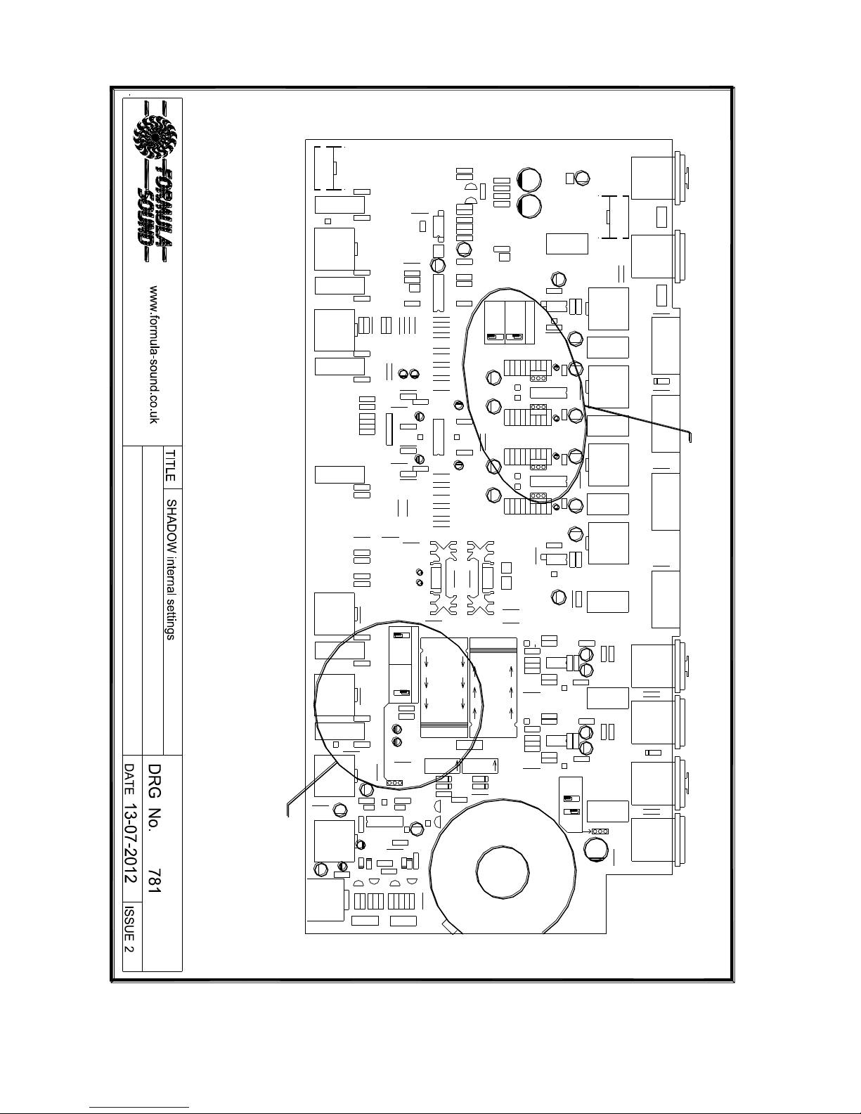
Remove the cover and referring to drawing 781 (towards the end of the manual) move the
jumpers indicated to achieve the required setting.
Refit the cover, ensuring screws are left inside the unit and no wires are trapped during refitting
of the cover.
Installation
Factory set channels 2 and 3 are phono (RIAA) inputs, to set either or both to line level inputs
refer to the settings section above in the manual.
Connect inputs (sources such as mic,CD,record etc) to the connectors marked “IN” on the input
section shown in fig 1 and fig 2 on the next page.
In the output section the connectors marked “OUT” provide the drive to amplifiers.

3
If the SHADOW is to be used for emergency/standby applications the inputs all have adjacent
connectors marked “OUT”, when the mixer is switched off the input is routed to its adjacent
output connector and can then be connected to a master mixer input.
Similarly the outputs have adjacent connectors marked “IN”, when the mixer is switched off the
output is routed to its adjacent input connector and can then be connected to a master mixer
output.
While the SHADOW is switched off the inputs are routed in and out of the SHADOW to the
master mixer, similarly the master mixer output is routed in and out of the SHADOW to the
amplifiers.
When the SHADOW is switched on the master mixer is bypassed and the SHADOW instantly
takes over.
----- Output section ---- ------------------- Input section -------------------
Fig 1
Fig 2
The location of gain trims for each input and the microphone two band EQ on the back panel
can be seen on fig 1 above.

4
Operation
Fig 3
With the inputs and output connected as required switch on the SHADOW and set the front
panel volume controls fully anti-clockwise and set all switches to off.
Set the MIC switch to on and set the MIC and master volume to three quarter position, speak
into the microphone and adjust the rear panel mic gain trim for the required level. Adjust the
rear panel mic EQ for the required sound (this is subjective). Switch the MIC off.
Set the channel 1 volume control to three quarters position and play music into channel 1,
adjust the rear panel gain trim for the required level. Set the channel 1 volume control fully anti-
clockwise when finished.
Repeat for channels 2 –4.
Play music into all 4 channels, all volume controls to be fully anticlockwise, connect
headphones and set the headphone volume control to mid position. Select and deselect cue on
channels 1 –4 in turn and check the music from the selected channel is present in the
headphones (if the headphones are set for split operation one side will be silent). If split
operation has been select cue on channel 1 and check channel 1 music is present on one side
of the headphones, increase the volume of channel 2 and check the music from channel 2
appears on the other side of the headphones.
Set all volume controls anticlockwise, select the XFADE, with the crossfader to the left increase
the volume of channel 1 and check it appears at the output, now set the channel 1 volume
control fully anti clockwise. Increase the volume of channel 2 and check it appears at the output,
now set the channel 2 volume control fully anticlockwise.
Increase the volume of channels 3 and 4 and check no music appears at the output.
Set all volume controls anticlockwise, select the XFADE, with the crossfader to the right
increase the volume of channel 3 and check it appears at the output, now set the channel 3
volume control fully anti clockwise. Increase the volume of channel 4 and check it appears at
the output, now set the channel 4 volume control fully anticlockwise.
Increase the volume of channels 1 and 2 and check no music appears at the output.
All functionality has now been checked.
www.formula-sound.co.uk
Formula Sound Limited
Unit 23; Stadium Business Centre
North End Road
Wembley
HA9 0AT

5
TECHNICAL SPECIFICATION
All inputs and outputs are paired with a second set of connectors, when the SHADOW is
switched off these connectors are connected together by a relay. Once the SHADOW is
switched on the second set of connectors are disconnected and the SHADOW is active.
Main output on XLR connectors (EQ set flat)
Distortion THD @ 1 KHz +10dBV <0.005%
Output impedance (Balanced) <100R
Max O/P (Into 600R) +25dBV
20Hz –20KHz +/- 0.5dB
Microphone input on XLR connector
Gain maximum 70dB
Noise ref 150R EIN<-125dB
Input impedance >2K ohm
Mic EQ (via presets on the rear panel)
Treble +/- 10dB @10KHz
Bass +/- 10dB @120Hz
Stereo inputs 1 –4 on gold plated phono sockets
Gain max +20dB
Noise EIN < -90dBV
Max input level +20dBV
Input impedance
Line 10KOhms
RIAA If selected on channels 3 and/or 4 47KOhms
Headphones
On ¼” 3 pole jack socket, use no less than 32 Ohms headphones
Power
220-240V AC standard (115V to order. Or consult user manual to change)
Mains fuse 220-240v operation 250mA slow blow
Mains fuse 110-115v operation 500mA slow blow
I.E.C. Mains connector
Finish
Front and Rear panels Bordeaux anodised aluminium with silver notation
Case black plastic coated steel
Dimensions
19" rack mounting. 1RU Width 482mm (19") Depth 200mm (7.9") Height 44mm (1.75")
Formula Sound reserve the right to alter the specification without notice.
6
L74
R15
EC6
VRF1
SW1
R11
DC19
VRDF1
R12
R16
R14
PC - 300
SOUND
FORMULA
T1
R5
R4
DC2
T2
R3
R6
R7
R1
EC1
C1
P2
P1
R2
EC2
U1
P5
DC1
R9
P3
R8
P4
EC5
C8 EC4
R13
R19
R10
C7
RL2
R
HF
D3FGH
1
X1
EC3
3
2
VRS1
D3MGH
X2
2
PR1
1
3
R66
R65
R64
R52
VRDF2
SW2
C9
R17 R18
R49
R50
R51
SW3
R53
L
R
R54
R55
R56
R63
R68
R59
R60
R62
R61
S1
SW4 R57
R58
L
EC22
P11
EC19
EC11
LINE INPUT
U7
C3
R22
JUMPER POSITIONS
CHAN 3 & 4
PHONO INPUT
P7
DC3
U2
DC4
R21
R20
P6
EC7
EC18
EC25
EC24
C5
R28
R27
R26
R25
R24
C2
C4
EC10
P10
EC8
R23
L
U4
DC8
H1
DC7
H2
CHAN 3
R L
PH SKT X4
RL3
VRDS1
LF
PR2
VRDS2
PS1
D8
H3
R67
DC11
DC12
R
EC26
L
R47
EC27
U6
R
R48
EC23
EC20
R35
R36
R38
R39
C15
C16
C17
R37
R34
R32
R33
R30
C10
C11
R31
R29
C6
EC9
R40
EC12
EC14
R
P12
EC21
R
H4
DC9
DC10
U5
CHAN 4
L
P13
EC15
R43
C12
C13
R46
R45
R44
R42
EC16
C14
R41
EC13
R
RL4
PH SKT X4
VRDS3
PS2
1
PH SKT X4
RL5 VRDS4
PS3
R103
PFL
SELECT PFL
R69
R70
R
R71
R72
VRDF3
SW5
ONLY
R105
R106
EC32
VRDF4
OUTPUT
L70
PFL
R100
R107 R99
VRDF5
SW6
DC20
EC33
R108
DC18
EC34
SELECT PFL JUMPER POSITIONS
EC29
3
D3FGH
R77
7818
EC40
EC41
DC5
MVR1
C19
P9
U3
DC6
C18
R73
P8
L
MVR2
7918
EC42
+
-
DC14
R74
EC17
R80
R81
R82
P14
R79
R78
PH SKT X4
RL6
PS4
1
EC28
R89
+
-
SPLIT
RL7
R84
R83 R85
U8
DC13
P15 R86
DC16 R90
P17
R96
R97
YEL
RED
R101
CK1CK2 GREEN
D1
H5
D2
D3
D4
R98
R91
R92
R93
EC43
R94
R95
U9
MAINS
EARTH
DC15
P16
OVE
TO
EC30
D3MGH
2
R75
R76
X3
L8 L9
2
3
X4
1
EC31
R87
R88
X5
D7
1
3
D3FGH
E
E
R110
R125
R112
D10
VRDF6
2
R109
P19
EC36
R104
EC39
U10
D9
D6
TO JACK SOCKET
EC37
EC38
TCW LINKS
R114
C
B
T8
R113
E
E
B
T7
C
C
B
T6
R115
P20
R116
R117
R118
R119
R120
P21
MAINS EARTH
R111
R102
P18
T3
DC17
T4
R123
EC35
DC21
D5
TXM1
LIFT
T5
C
B
R124
22
RL1
1
H6
3
X6
D3MGH
EC44
R121
R122
1. Channel 2 and 3 LINE or PHONO (RIAA) setting.
2. Headphone monitoring, input only or split input and output.
Move jumpers as silk screen legend on PCB indicates for required settings

7
FORMULA SOUND LIMITED
UNIT 23; STADIUM BUSINESS CENTRE; NORTH END ROAD; WEMBLEY; MIDDLESEX; HA9 0AT
TELEPHONE +44 (0)208-900-0947 FAX +44 (0)208-903-8657
www.formula-sound.co.uk email info@formula-sound.co.uk
E.U. CERTIFICATE OF CONFORMITY
We declare that the products listed conform to the following directives and standards
89/336/EEC amended by 92/31/EEC and 93/68/EEC
BS EN 50082-1 BS EN 50081-1
PRODUCT TYPE
SHADOW
The CE mark was first applied in 1995
Signed
B. J. Penaligon General Manager
Attention
The attention of the specifier, purchaser, installer, or user is drawn to the fact that good wiring practice must be
observed when connecting the above equipment. Good quality connectors and screened cables must be used for all
audio connections. Twin screened cables should be used for all balanced lines.
THIS EQUIPMENT MUST BE EARTHED
CONSULT THE USERS MANUAL FOR TECHNICAL DETAILS
Table of contents
Other Formula Sound Music Mixer manuals


