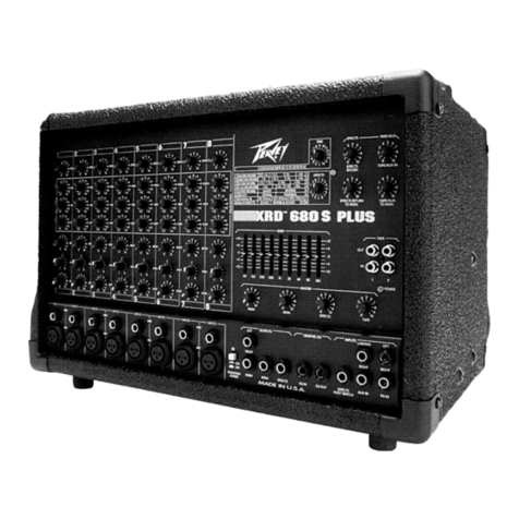
Formula Sound FF - 6000 User manual

FF - 6000
DUAL FORMAT DJ MIXER
USERS MANUAL

FF - 6000 INTRODUCTION
ThefeaturesandlayoutoftheFF-6000weredeterminedincollaborationwithleading
loudspeakermanufacturersFunktionOne,whocanvassedmanyDJs world wideontheir
requirements. The result is a mixer which is not only of the highest sound quality, as you
would expect from Formula Sound, but also incorporates the features and layout which DJs
have asked for.
AlthoughtheFF-6000isafixed format design the use of individual circuitcardsperchannel,PTH
circuitboards,andallrotarycontrolssecurelymountedtothefrontpanel, improve reliability and
aidservicingshould the need arise.
Arearprintedpolycarbonateoverlayto the top panel ensures that this mixerwillstilllookgood
after many years of use and notation will never rub off.
TheFF-6000is essentially a seven channelmixer.Sixofthese channels are laid outtothe leftof
themastersectionandtheseventhisadedicatedmicrophonechannellabelled‘ConsoleMic’
positioned to the right of the master section
The six channels are each switchable to two input sources. Channels 1 and 2 are switchable
between low impedance microphone and a stereo line input. Phantom power is available for
microphones (internal selection).
Channels3to6areswitchablebetweenastereolineinputand a phono (RIAA) or line input.
(Phono/lineselectionis via a concealed push switch accessible through a hole intherearpanel).
These6input channels are fully assignable to the crossfader,andfeaturespeciallydesigned
threebandequalisationwith a range of +5dB to-23dB.
Gaintrimsareprovided for all inputs accessible throughtherearpanel, as well as a frontpanel
gaincontrol.Anadjacent5 segment led meter and clip warning indicator provide signal present
indicationand overloadwarning.Illuminatedpush switchescontrolinputselection, channelrouting
andcue,etc.Differentshapesandsizesofpushbuttonsalongwith colour coded illumination
helptoeasilyidentify control functions .
Removable Fader Panel
Thefader panel mounted beneaththe6inputchannelsis removable and availablewitheither
linearor rotary faders. This providesfor easy removaland replacement of all faders which are
allconnectedby gold plated connectors.Ascrewdriver is the onlytoolrequired to replace afader
orchange the mixer froma linear torotary fader operation.
SmoothfeelAlps60mmfaders which are arrangedto eliminate theingress of dirt areused for
thelinear fader option andsuperior quality rotaryfaders are used for the rotary option.
1

Master Section Overview
MainandZoneoutputsareavailable in stereo, along with a separatemono output.Allthese
outputsarebalanced on XLR connectors.Boothmonitors output is availablein stereo or
switchabletomonoandagaintheseoutputsarebalancedonXLRconnectors.
Arecordingoutput is provided ongoldplated phono sockets.
Thereare 3 insert loopsprovided. 1 &2 are selected via the X-fade assignbuttons and feature
latchingandpunchselectorbuttonsalongwithwet/drymixingcontrol and gain trims. Mono and
cueswitchesare fitted to both sections.Thereis also an illuminated loopswapbutton that allows
theconnectedeffects processors to beswappedover to the otherchannel.
Thethirdeffects loop is connected tothemain output chain. This isselectedby an illuminated
pushbutton.
Alleffectsloop connectors are pairsof3 pole jacks, eachsocket providing send and return
paths.
Visualmeteringis by 2 twin12segment led VU meters;one for cue signals andone for output
signals.
Comprehensiveheadphones monitoring is provided featuring apowerfulstereoheadphones
amplifier.
6.5mmand3.5mmstereojacksare provided.
Asplitcueswitchandmonitor balance control are fitted.
TheConsoleMicrophonechannelislocatedabovethephonessectionandfeatures two band
equalisation,volume control, illuminated on-off switch andcuebutton.
Dimensions (Exc.Knobs & connectors):
Width483mm (19”) Height312mm(12.25"-7RU) Depth110mm (4.33")
PowerSupply
TheMixerhasafullyregulatedinternalpowersupplythatisdesigned to operate on
220-240Vacor 110-120Vac.Selection is by an internal switch thatisaccessedbyremovingthe
faderpanel.
DAMAGE MAY RESULT IF THE UNIT IS CONNECTED TO THE WRONG
SUPPLY VOLTAGE.
Fuses
Mainsfusesizes are 800mAanti-surge for 220-240Vacand1.5Aanti-surgefor 110-120Vac
operation.
It is important for safety reasons that the correct fuse sizes are always
used.
2

INPUT CHANNELS 1 AND 2
InputSources.Thesechannels have balancedlowimpedancelow
noisemicrophoneinputs on XLRconnectorsand a normalstereoline
inputontwin gold platedRCA phono connectors.
Input selector switch selects the input used.
Button depressed selects Mic (XLR connector)
Button not depressed selects Stereo line input.
Blueand redl.e.d.s. andlabels clearlyshow whichinput isin use.
Channelmeter.This isa 5segment l.e.d. meter and itdisplays the
signallevel within thechannel. The normalreading forthis meter is
amberwith occasionalpeaks into to the red.
Gaincontrol. This setsthe input gainlevel, andshould be usedin
conjunctionwith the rearpanel gain trims.Againtrimmerisprovided
forevery input so that allinput sources can be matchedto the same
level.The controlis thenused tocompensate for differences in track
levels.
Clipindicator.Thisis ared l.e.dthat indicateswhen thechannel
signal is just below clipping. If lit it means that the gain is set too high.
3Band equalisation provides +5dB boostand -23dBcut @
HF10kHz MID 1kHz BASS100Hz.
Thecentre detentdenotes theflat position.
X-FadeAandB.Rectangularpush button switches with red and
green illumination. Depressing the switches routes the channel via
theVCA controlledcrossfader andassociated effectsloops if
selected.
Thechannel signalmay berouted toeither endof the
X-fader.
Theredand green colourcodingis maintained throughoutthe
X-faderand associatedeffects loopsto giveclear visualindication of
routingstatus.
If neither button is depressed the signal is routed directly to the
output section.
Cue. Alargerroundilluminated pushbutton is providedfor cue
selection.When depressed thechannel signalis fedto the cuebuss.
Anynumber of sourcesmay beselected simultaneously,the sum of
whichwillbe available totheheadphones monitoring section.
Fader. A 60mm channel fader (or rotary fader depending on what
fader option has been fitted ) is available to mix the various
channels as required.
3
MIC
LINE
GAIN
CLIP
2
X-FADE A
B
CUE
HF
MID
BASS

PH/LINE
LINE
GAIN
CLIP
3
X-FADE A
B
CUE
HF
MID
BASS
INPUT CHANNELS 3 to 6
InputSources.These channels havea stereo RIAAphonostage and
anormal stereo lineinput bothon twingold plated RCAphono
connectors. The phono stage may be configured as a second line
inputbydepressing a concealedpushswitch available throughahole
inthe rearpanel.
Input selector switch selects the input used.
ButtondepressedselectsPhono/line(depending on configuration).
Button not depressed selects Stereo line input.
Blueand redl.e.d.s. andlabels clearlyshow whichinput isin use.
Channelmeter this isa 5 segment l.e.d. meter and it displays the pre-
fadersignal level withinthe channel. The normalreading forthis
meteris amberwith occasional peaks into thered.
Gaincontrol. This setsthe input gainlevel, andshould be usedin
conjunctionwith the rearpanelgain trims.Againtrimmer is provided
forevery input so that allinput sources can be matchedto the same
level.The controlis thenused tocompensate for differences in track
levels.
Clipindicator.Thisis a red l.e.d thatindicates whenthe channelsignal
is just below clipping. If lit it means that the gain is set too high.
3Band equalisation provides +5dB boostand -23dBcut @
HF10kHz MID 1kHz BASS100Hz.
Thecentre detentdenotes theflat position.
X-FadeAandB. Rectangularpushbutton switcheswith redand
greenillumination.Depressingthe switches routesthechannelviathe
VCAcontrolled crossfaderand associatedeffects loopsif selected.
Thechannel signal may be routedto eitherend ofthe
X-fader.
Theredand green colourcoding are maintainedthroughout the
X-faderand associated effects loops togive clearvisual indicationof
routingstatus.
If neither button is depressed the signal is routed directly to the
output section.
Cue. Alargerroundilluminated pushbutton is providedfor cue
selection.When depressed thechannel signalis fedto the cuebuss.
Anynumber of sourcesmay beselected simultaneously,the sum of
whichwillbe available totheheadphones monitoring section.
Fader. A 60mm channel fader (or rotary fader depending on what
fader option has been fitted ) is available to mix the various
channels as required.
4

OFF
Assignment
Contour
To Both A & B
Direct to Masters
AB
CUE CUE
CUE
Punch Punch
Latch
ON Latch
ON
ZONE MASTER
LEVEL LEVEL
CONSOLE
MIC
MIC ON
INSERT
IN / OUT
HF
LF
CUE O / P
O / P
Meter
LR
Bal / Pan
MONO MONO MONO
Bal / Pan
LR
Dry Wet
Fx Mix
X-FADE
dB
0
-1
-10
-15
-20
-3
-5
-7
+1
+3
+5
+8
dB
0
-1
-10
-15
-20
-3
-5
-7
+1
+3
+5
+8
VOL
CUE BAL
CUE MIX
SPLIT
PHONES
BOOTH
MONITORS
Fx Loop 1
Fx Loop 2
Fx Loop 1
Fx Loop 2
LOOP
SWAP
Trim FX 1 FX 2
32 Ohm
Trim
Dry Wet
Fx Mix
Master section
The master section contains all the
electronics required for the various summing
amplifiers, output stages, VU meters,
crossfade control circuits, etc.
Monitoring
The monitoring section of the FF-6000 is
very comprehensive. Visual monitoring is
provided by 2 stereo 24 segment l.e.d.
bargraph meters, 1 for cue signals and one
for output signals.
Apowerful stereo headphone amplifier is
incorporated designed to drive headphones
of 32 ohms or greater. Connections are via
a 6.5mm or a 3.5mm 3 pole jack socket.
Simultaneous use of both sockets is not
possible.
The cue meter and the phones output are
both connected to the same signal so what
you see is what you hear.
CUE BAL (Cue Balance)
It is important that the function of this control
is fully understood.
The output from this control is fed to the
monitoring section (the cue bargraph meter)
and via the PHONES volume control to the
main phones output.
With the control turned fully counter
clockwise towards cue, the meter will read
the cue signal of any channel or effects loop
that has its cue button depressed, or the
sum of channels if more than one is
selected. If no cue buttons are depressed
the meter reads the main output level which
is dependent on the MASTER control
setting.
Turning the monitor balance control clockwise towards MIX feeds the programme signal (pre master) to the
monitoring section. Therefore the operator can quickly pan or mix between the PFL and mixer output. It also
facilitates the monitoring of a recording being made with the master turned down.
A SPLIT button is also provided (which is the preference of some operators). This provides a mono CUE
signal on one side of the monitor system and a mono program signal on the other side. The Mon Bal sets the
balance of the two signals in this situation. Practice and use will determine the best mode of operation.
Do not use headphones with an impedance lower than 32 ohms.
MASTER - This control sets the output level of the main balanced stereo and mono outputs, available via 3 pin
XLR connectors on the back panel. This output is monitored by the main phones and VU meter when the CUE
BAL control is set to CUE and no CUE is selected. The VU meter is factory calibrated 0dB = 0dBu (775mV)
ZONE -The zone output is almost identical to the main output in all respects except that the signal is not
available to the headphones monitoring section. The zone output level may be checked by depressing the
O/P Meter button located beneath the ZONE LEVEL control. This switch allows the o/p meter to read either
main output or zone output.
RECORD OUTPUTS - A pair of gold plated phono sockets are provided for the connection of stereo
recording equipment. The record outputs are not affected by the master level controls.
5

Mastersectioncontinued
BOOTH MONITORS - This control adjusts the level of the booth monitors output which is a mix of
channels1 to 6 only (consolemicrophone notpresent ineither output). Thebalanced outputsare via 3
pinXLR connectors. Amonosignal maybe obtainedby usingmono button located above.
INSERTS - General information
Insert sockets in the form of 3 pole 1/4” jacks are provided in pairs for the connection of external
signal processing or effects equipment. Located on the back panel the connections are:-
Tip = send (mixer output)
Ring = return (mixer input)
Body=common(ground)
Socketsare providedfor effectsloops 1and 2and themain outputchannels
INSERT IN / OUT - This switchallows theselection ofexternal equipmentinserted intothe main insert
sockets.This affects themain andzone outputs.
FX LOOPS 1 and 2 - Very comprehensive facilities are provided for adding external effects into the
mix. The two loops provided have identical controls.
Routingto theeffects loops follows the X-fadeassign buttonson channels 1 to 6.
Theeffects sendsignals may be reduced viaa rearpanel trimmer located above theloop connectors.
Thisis toensure thatoverloading ofsensitive inputstages isavoided andthe correctlevel isavailable to
effectsprocessors.
Aneffectsreturn gain trimmer( FX1Trimand FX2Trim) allows thecorrect level to be reintroduced into
themix.
Dry / Wet - Onceenabled this control mixes betweenthe directsignal (effects unit input) andthe effects
unit output. It is provided to mix the required amount of effect. With the control set to fully Dry no effect
is added. With the control set to fully Wet just the effect return is added to the mix and the original signal
isremoved. Momentary punch and latching switchesenables theWet /Dry controls.
CUE - This button allows the operator to set up the required effect on the headphones before the effect
isselected.
LOOP SWAP - This switch allows the effects processors to be swapped e.g. if just one processor was in
use and connected to FX1 ( routed from X-FA) it could be used in loop 2 (routed from X-FB)
just by depressing LOOP SWAP. The red and green l.e.d.s also change over as a reminder that Swap is
selected.
CROSSFADE - Thecrossfader is a 45mm faderwhich canbe used to smoothly fadebetween the XF-A
andXF-B bussesand any added effects.
Thecrossfade systemuses studioquality V.C.A.’s(voltagecontrolledamplifiers) to improve crossfader
lifeand alsoensure goodattenuation atthe ends of travel.
CONTOUR -Acontourcontrol is providedwhich allows the operator toadjust the crossfader
characteristics to suit personal taste, from a gentle fade betweenAand B to a more aggressive fade
towards the ends of the fader.
CROSSFADE OFF -Anilluminatedpush switchoperated througha holein the front panel isfitted below
thecontour control.When depressed the crossfader isdisabled. Both FX1and FX2 loops will stillbe
operational.
CONSOLE MIC - Adedicatedmicrophonechannel isavailable.The controlsare positioned to the top
rightcornerabove the headphonessection.
Twoband equalisationis fittedproviding +/- 12dB @ 10kHz (HF) and +/-12dB @100Hz(LF)
AnilluminatedON/OFF push switch, volumecontrol,and illuminated CUEpushswitchcomplete the
controls.ThisMicrophone channelisnot presentinthe boothmonitors.
6

Operational Information or how to get the best out of your mixer
Gain
In an audio mixer different signal levels from various items of equipment need to be amplified or
attenuated to a common level so that they can be added or mixed together. These signal levels may
differconsiderably depending onthe equipment. The signalfrom amicrophone, for example,may be
1000 times smaller than that from a CD player. For a mixer to be as flexible as possible and to
accept signals from a variety of equipment it is necessary for the first or early stage in the input circuit
to be a variable gain amplifier. The gain of this amplifier is set by the gain control.
The FF-6000 has a combination of variable gain amplifiers to get the input signals to the required
operating level. Gain trim presets are fitted - 1 for each input. These are accessible through holes on
theback paneland arelabelled accordingly. Thestereo inputgain trimsare conventional singleturn
controls. TheMic presetis a multi-turn trimmer. These trimsshould beadjusted to set the maximum
gainavailable forany input. Thefront panelgain controlworks inconjunction withthese presets. The
systemmay beconsidered as coarse gain controlon therear presets and fine adjustmenton thefront
gaincontrol.
Whenamplifier gainis introducedin acircuit noiseis alsointroduced. (Thisis afact -you cannothave
onewithout theother). The FF-6000 has been designedto keepthis noise as low aspossible byusing
the latest technology. For the best performance set the gain control as low as possible to achieve the
desiredoutput level. Gainintroduced intothe systemand then held on the channel faderis awaste of
performance. Toomuch gain couldresult inoverloading the firststagecausingdistortion andclipping.
A clip indicator has been included and is located below the front panel gain control. This indicator
flashes when the signal level is close to clipping. It monitors the signal at various points in the signal
chain, therefore, gain introduced by the equalisation or tone controls is also considered.
IF THE PEAK INDICATOR ILLUMINATES DURING USE TURN DOWN THE GAIN CONTROL (OR
INPUT TRIM PRESETS).
INSTALLATION, CONNECTIONS AND GOOD WIRING PRACTICE
The installation of professional audio systems should be left to experienced engineers wherever
possible. The interconnection of audio systems can be fairly complex depending on the type and size
of system and obviously well outside the scope of this handbook. We have included a few basic
points for information for anyone who is new to audio systems.
Good wiring practice should be observed when connecting any audio equipment. Good quality
connectors and screened cable should be used for all audio connections .
Twin screened cable should be used for all balanced lines particularly microphone connections.
Always ensure cable clamps in connectors are fully tightened and gripping the outer sheath. Good
strain relief and mechanically sound connections will increase reliability at virtually no extra cost.
GROUND LOOPS
In our experience this is the most common problem encountered when connecting together different
items of audio equipment. It is the most common cause of hum (50Hz noise) on a system and is
caused by incorrect system grounding.
When several items of audio equipment are connected together with unbalanced connections (i.e. 2
connections, single screened cable, etc.) the signal common connection is the screen and this will be
connected to mains earth at some point. If several items of equipment have their signal common
connected to mains earth this will form a loop (hence ground loop). Current will flow in this loop and
appear in the form of hum (50Hz mains frequency) added to the audio signal. The problem is
aggravated if the equipment is located a distance apart as the loop is larger. It is possible to have
several ground loops within a system.
The solution is to connect the system to mains ground
only once
. This is usually done at the mixer. You will need to investigate the various items of
equipment you are using and isolate their signal common from mains earth. Many manufacturers fit a
ground lift switch for this purpose. On some equipment this is in the form of a removable link.
Unfortunately with some equipment you have to get inside to identify where the connection is and
remove it.
You must not disconnect the mains earth wire from the mains plug of any equipment. This is
fitted for safety reasons and must be connected to ensure that the case is earthed.
7

FormulaSoundreservetherightto alter specifications at any time without notice.
AllFormula Sound products are designed andmanufacturedinourownfactorywhichenables us
tomaintainstrict quality at every stageofmanufacture. This attention to detail hashelpedto win
us14industryawardstodateandhasearnedusaworld wide reputation for the high quality and
reliabilityofour products.
FormulaSound Ltd.
AshtonRoad,
Bredbury,
Stockport,
Cheshire,
England.
SK6 2SR
Tel+44(0)161 494 5650
Fax+44(0)161 494 5651
E-mail[email protected]
Internethttp://www.formula-sound.com
8

FF- 6000 Specifications
Frequency response
E.Q. set flat 20Hz - 20kHz +/-0.5dB
Maximum output level
Main output Zone output and Booth monitors output
active balanced. +22dBu
Distortion
anyinput < 0.01% typically <0.005%
Noise measured 20Hz-20kHz
Stereo inputs e.q. flat gain set to max EIN < -98dB
RIAA stage ref. 5mV 1kHz Input shorted -80dBV “A” weighted
Microphone input (ref 150R) EIN < -124dBU
Gain
Stereo inputs rear trim @ max +/- 15dB
Stereo inputs rear trim @ min + 0dB -20dB
Microphone input max + 75db
Microphone input min + 0dB
Maximum input level
Stereo inputA(line) +20dBV
Stereo inputA(RIAA) -8dBV 400mV
Stereo input B +20dBV
Microphone +4 dBV
Input Impedances
Stereo inputA > 47k ohms
Stereo input B > 10k ohms
Microphone input > 2k ohms active balanced
Equalisation
3 band e.q. per channel +5dB -23 dB @ Treble 10kHz
Mid 1kHz,
Bass 100Hz
Dimensions
(Exc. Knobs & connectors): Width 483mm (19”)
Height 312mm (12.25"-7RU)
Depth 110mm (4.33")
Balanced outputs For unbalanced operation strap pins 1&3 to ground and use pin 2 hot. This will result in no
loss of output level or performance.
Table of contents
Other Formula Sound Music Mixer manuals
