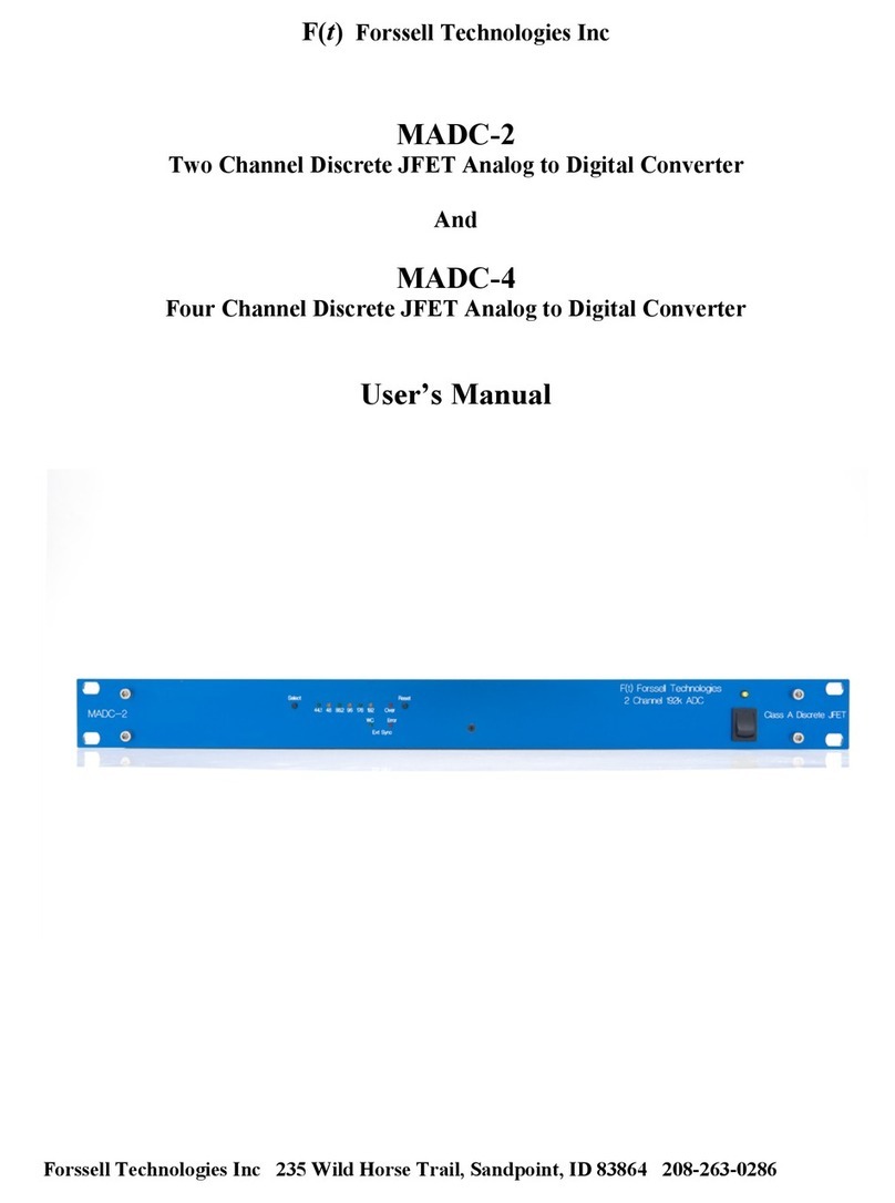
Forssell Technologies MADA-2 User manual

F(t) Forssell Technologies Inc
MADA-2
2 Channel Analog to Digital and Digital to Analog Converter
User Manual
72311

General Description:
The Forssell Technologies MADA-2 is an extremely high quality two channel Analog to Digital
Converter (ADC) and two channel Digital to Analog Converter (DAC) housed in a 1U rack mount
enclosure. The MADA-2 can be powered from 115 or 230 volt 50/60 Hz line voltages. An internally
mounted switch selects which line voltage can be used.
The MADA-2 has AES3 and SPDIF digital inputs and outputs, as well as a Word Clock input and
output. Analog inputs and outputs are balanced and floating so that they can used with either balanced
or unbalanced signals. Using the MADA-2 with unbalanced analog signal sources will result is slightly
worst distortion figures when compared with a balanced analog signal source. No such compromise in
performance exists for the analog outputs.
Analog to Digital (ADC) Section Description:
The ADC section of MADA-2 is a high quality two channel Analog to Digital Converter. The MADA-
2 is designed for the most demanding applications, where capturing musical performances with accuracy
and honesty is required. Output sample rates from 44.1k to 192k Fs are selected with a single front
panel switch and with LED indicators showing the selected sample rate. Digital “clipping” is indicated
with a single front panel LED that latches on until the “reset” switch is pressed. The MADA-2 analog
circuitry features an all Class A discrete JFET with no IC opamps used in the signal path. The analog
inputs use high quality XLR connectors. The digital outputs provided are AES3 (XLR), SPDIF (RCA),
WC Sync input and Word Clock output (BNC) are provided. An additional Word Clock output is
available as an option. The MADA-2 digital output word length is fixed at 24 bits.
The MADA-2 uses a 32 bit asynchronous decimation filter to provide various standard output sample
rates from 44.1K to 192k. The actual low jitter sampling clock that controls the AD converter chip
timing is permanently set to sample at 196.3 kFs regardless of output sampling rate selection. This
process is called Asynchronous Sample Rate Conversion (ASRC) and is performed by a 32 bit sample
rate converter. The output from the ASRC circuitry is 24 bit at the selected output sample rate.
Please note that there are no provisions for word length reduction, or level metering with this
converter.
Word Clock Output:
The MADA-2 has a single low jitter word clock output available on a rear panel mounted BNC
connector. This output is designed to operate into a 75 ohm terminated coaxial cable. The output
voltage is TTL compatible. The WC output follows the output sample rate, as selected by the front
panel control. Additional WC outputs are provided on the MADA board, but the user would have to
install their own connectors and wire them to the MADA board.
Output Sample Rate selection:
The output sample rate of the MADA-2 is selected by the single front panel mounted “Select” switch.
The LEDs to the right of this switch indicate the output sample rate currently selected. The MADA-2
does not remember this setting when power is removed. If your sample rate is other than 44.1k, then
you must reset the output sample rate to the desired sample rate each time the unit is powered up.
“Over” LED:
The front panel mounted red “Over” LED lights when any channel reaches a digital signal level that is
within 0.1 dB of digital full scale for more than two sample periods. Once lighted, the over LED will
remain lighted until the “reset” switch is press. The reset switch only effects the “Over” LED and does

not reset the converter digital circuitry nor does it change the sample rate back to power up defaults.
Each time you power up the MADA-2, the “Over” LED will light up. Press the reset switch to turn-off
the Over LED.
External Sync Input:
Your MADA-2 is supplied with an External Word Clock Sync function External Sync is selected by
pressing the “Select” switch until the WC external sync LED is lighted. If no valid WC is detected at
the WC Input BNC connector, then the red SYNC LED will be lighted. Once a valid WC is applied to
the BNC connector, the red LED will turn off, indicating that the MADA is locked to the external WC.
The MADA-2 should lock within one second of receiving a valid WC sync input signal. A wide range of
WC input frequencies can be used, including vari-speed WC signals.
The WC sync input level should be TTL compatible and needs to be terminated with a 75 ohm resistor.
The MADA-2 WC input is a high impedance input. This allows several units to be feed sync input with
from one single WC source. To daisy-chain several units, you will need to use BNC Tee connectors on
each unit. A 75 ohm terminator should be connected at the Tee connector of the very end of the chain.
Analog Inputs:
Analog inputs are provided on rear panel mounted XLR connectors. The MADA-2 can accept either
balanced or unbalanced input signals. Unbalanced signals result in a 6 dB lower headroom. The XLR
connectors are wired for pin #2 = + input, and pin #3 = - input signal polarities. The input impedance of
analog inputs is approximately 3k ohm balanced.
Level Calibration:
Unless otherwise requested when your unit was ordered, the MADA-2 is calibrated so that a 0 (775
mv) dBu analog input level produces –18 dBFs digital output level. There are four sets of jumpers
located on the MADA board inside the MADA-2 that will allow you to change the level calibration for
the AD section. All four jumpers must be set for the same level calibration.
Digital Outputs:
There are two digital outputs available with the MADA-2. One is an AES/EBU (AES3) 110 ohm digital
output on a rear mounted XLR connector. The other is a 75 ohm SPDIF digital output on a rear mounted
RCA connector. These digital outputs are isolated from each other and they may be used
simultaneously.
Digital to Analog (DAC) Section Description:
The DAC section MADA-2 is designed for the most demanding applications, where capturing musical
performances with accuracy and honesty is required. The MADA-2 accepts digital inputs with sample
rates from 44.1k to 192k Fs. The MADA-2 has AES3 (AES/EBU) 110 ohm on an XLR connector and
SPDIF 75 ohm RCA inputs. Input selection is via a front panel push button switch with LED
indicators showing which input is selected. Other front panel LED indicators show input fault
condition and SCR lock status.
Level Calibration:
Unless otherwise requested when your unit was ordered, the MADA-2 is calibrated so that a -18 dBFS
digital input level produces a 0 dBu (775 mV) analog output level. There are two trim pots located on

the MDAC board inside the MADA-2 that will allow you to change the level calibration for the DA
section.
Digital inputs
There are two digital inputs on the MADA-2. One is configured as an AES-3 or AES/EBU input, and
the other is an SPDIF input. The AES-3 input is a 110 ohm, transformer isolated, and balanced XLR
input. Pin #1 of this input is connected to chassis ground through a 0.1 mfd capacitor . The SPDIF
input is a 75 ohm single-ended RCA input.
Analog Outputs
The analog output of the MADA-2 are balanced and floating with an output impedance of less than 5
ohms. Either balanced or single-ended loads may be connected to the output of the MADA-2 without
problem. When a single-ended load (unbalanced) is used, be sure to take the signal between pin #2 (hot)
and pin #3 (cold) of the input XLR. Pin #1 can be connected to either of these pins if desired.
Connecting pin #1 to pin #2 will produce an output signal that is out of phase, so normally pin #1 is
connected to pin #3 for single-ended loads. Pin #1 can be left floating too.
MADA-2 Specifications:
ADC specifications:
Sample Rates available : 44.1k, 48k, 88.2k, 96k, 176.4k and 192k
Level Calibration : 0 dBu Input = -18 dBFs
(Other calibration levels available on request.)
Analog Input Impedance = greater than 10k ohm balanced
Maximum analog input level is a function level calibration (no analog clipping).
AES3 (XLR) digital output impedance = 110 ohm balanced floating
SPDIF (RCA) digital output impedance = 75 ohm balanced floating
WC output = +5V (TTL) unterminated. Requires 75 ohm load termination at load.
ADC Latency (Input to Output group delay):
Fs Time
44.1k 1.6 ms
48k 1.48 ms
88.2k 967 us
96k 895 us
176k 660 us
192k 605 us

DAC Specifications:
Noise <= -120 dBFs A-weighted
Quantization Noise <= -117 dBFs 400 to 22 KHz unweighted
Dynamic Range > = 123 dB
THD+N (%) = 0.0009% @ 1Khz 0 dBu output (-18 dBFs input) 600 ohm load
THD+N (%) = 0.001% @ 1Khz +18 dBu output (0 dBFS input) 600 ohm load
IMD (SMPTE) = 0.001% @ 0 dBu output (-18 dBFs input) 600 ohm load
IMD (SMPTE) = 0.003% @ +18 dBu output (0 dBFs input) 600 ohm load
DAC Latency
Fs Time
44.1k 1.97 ms
48k 1.8 ms
88.2k 1.13 ms
96k 665 us
176k 712 us
192k 678 us
Analog in to Analog Output Specifications:
Noise Floor = -96 dBu unweighted 22 to 22 KHz
THD+N (%) = 0.001 % with 1Khz 0 dBu input/outout (-18 dBFs)
THD+N (%) = 0.008 %Fs with 1Khz +18 dBu input/output (0 dBFS)
IMD (SMPTE) = 0.002% with 0 dBu input/output (-18 dBFs)
IMD (SMPTE) = 0.05% with +18 dBu input/output (0 dBFs)
General Specifications:
Power consumption = 14 watts @ 120 VAC
AC Line Voltage range = 110 to 125 VAC and 220 to 250 VAC 50 or 60 Hz
AC Line Voltage:
The MADA come preset for either 115 VAC or 230 VAC 50/60 Hz operation as indicted by a rear panel
label. The line voltage is selected by a line voltage switch mounted inside the MADA chassis. Changing
the line voltage from the factory setting requires a change to the AC line fuse which is located within the
AC power entry module on the rear panel. You must use one of the following fuse values…
115 VAC use 250 milliamp TD fuse.
230 VAC use 100 milliamp TD fuse.
Line voltage changes should only be made by a qualified technician.

DAC Measurements
D-A FFT HiRes Stereo.at 2c
-140
+0
-135
-130
-125
-120
-115
-110
-105
-100
-95
-90
-85
-80
-75
-70
-65
-60
-55
-50
-45
-40
-35
-30
-25
-20
-15
-10
-5
d
B
u
2k 32k4k 6k 8k 10k 12k 14k 16k 18k 20k 22k 24k 26k 28k 30k
Hz
DA FFT (linear scale) of 2 KHz signal at 0 dBu output level with a 600 load. Red = Ch1 Blue= Ch2
D-A FFT HiRes Stereo.at 2c
-140
+0
-135
-130
-125
-120
-115
-110
-105
-100
-95
-90
-85
-80
-75
-70
-65
-60
-55
-50
-45
-40
-35
-30
-25
-20
-15
-10
-5
d
B
u
20 30k50 100 200 500 1k 2k 5k 10k 20k
Hz
DA FFT (log scale) 2 KHz signal at 0 dBu output level with a 600 load. Red = Ch1 Blue= Ch2

D-A FFT HiRes Stereo.at 2c
-140
+0
-135
-130
-125
-120
-115
-110
-105
-100
-95
-90
-85
-80
-75
-70
-65
-60
-55
-50
-45
-40
-35
-30
-25
-20
-15
-10
-5
d
B
u
2k 32k4k 6k 8k 10k 12k 14k 16k 18k 20k 22k 24k 26k 28k 30k
Hz
DA FFT (linear scale) 2 KHz signal at -100 dBu output level. Red = Ch1 Blue= Ch2
D-A FFT HiRes Stereo.at 2c
-140
+0
-135
-130
-125
-120
-115
-110
-105
-100
-95
-90
-85
-80
-75
-70
-65
-60
-55
-50
-45
-40
-35
-30
-25
-20
-15
-10
-5
d
B
u
20 30k50 100 200 500 1k 2k 5k 10k 20k
Hz
DA FFT (log scale) of 2 KHz signal at -100 dBu output level with a 600 load. Red = Ch1 Blue= Ch2

D-A FFT HiRes Stereo dual freq.at2c
-140
+0
-135
-130
-125
-120
-115
-110
-105
-100
-95
-90
-85
-80
-75
-70
-65
-60
-55
-50
-45
-40
-35
-30
-25
-20
-15
-10
-5
d
B
u
2k 32k4k 6k 8k 10k 12k 14k 16k 18k 20k 22k 24k 26k 28k 30k
Hz
DA FFT (linear scale) of Dual Freq (19 and 19.5 KHz) signal at 0 dBu Output Level.
D-A FFT HiRes Stereo dual freq.at2c
-140
+0
-135
-130
-125
-120
-115
-110
-105
-100
-95
-90
-85
-80
-75
-70
-65
-60
-55
-50
-45
-40
-35
-30
-25
-20
-15
-10
-5
d
B
u
20 30k50 100 200 500 1k 2k 5k 10k 20k
Hz
DA FFT (log scale) of Dual Freq (19 and 19.5 KHz) signal at 0 dBu Output Level.

D-A FREQ RESP. at2c
-3
+1
-2.8
-2.6
-2.4
-2.2
-2
-1.8
-1.6
-1.4
-1.2
-1
-0.8
-0.6
-0.4
-0.2
+0
+0.2
+0.4
+0.6
+0.8
d
B
r
A
10 40k20 50 100 200 500 1k 2k 5k 10k 20k
Hz
DA Frequency Response at 96 KHz sample Rate
D_A Jitter Spectrum 0.at27
-160
+0
-150
-140
-130
-120
-110
-100
-90
-80
-70
-60
-50
-40
-30
-20
-10
d
B
r
A
20 20k50 100 200 500 1k 2k 5k 10k
Hz
DA Jitter FFT (44.1k Fs) with 1 KHz 0 dBFs sine wave signal and 500 Hz sine wave jitter at 1 UI
(177 ns) amplitude

D-A LINEARITY. at2c
-2.8
+3
-2.6
-2.4
-2.2
-2
-1.8
-1.6
-1.4
-1.2
-1
-0.8
-0.6
-0.4
-0.2
+0
+0.2
+0.4
+0.6
+0.8
+1
+1.2
+1.4
+1.6
+1.8
+2
+2.2
+2.4
+2.6
+2.8
d
B
r
A
-110
+15
-105
-100
-95
-90
-85
-80
-75
-70
-65
-60
-55
-50
-45
-40
-35
-30
-25
-20
-15
-10
-5
+0
+5
+10
d
B
u
-130 +0-120 -110 -100 -90 -80 -70 -60 -50 -40 -30 -20 -10
dBFS
Deviation from Linearity (Right scale) with 0 dBFs to –130 dBFs (Input).
ADC Measurements
A-D FFT.at2c
-160
-20
-155
-150
-145
-140
-135
-130
-125
-120
-115
-110
-105
-100
-95
-90
-85
-80
-75
-70
-65
-60
-55
-50
-45
-40
-35
-30
-25
d
B
F
S
1k 22k2k 3k 4k 5k 6k 7k 8k 9k 10k 11k 12k 13k 14k 15k 16k 17k 18k 19k 20k 21k
Hz
AD FFT (linear scale) with 0 dBu 5 KHz input (-18 dBFs digital output).

A-D FFT.at2c
-160
-20
-155
-150
-145
-140
-135
-130
-125
-120
-115
-110
-105
-100
-95
-90
-85
-80
-75
-70
-65
-60
-55
-50
-45
-40
-35
-30
-25
d
B
F
S
20 20k50 100 200 500 1k 2k 5k 10k
Hz
AD FFT (log scale) with 0 dBu 5 KHz input (-18 dBFs digital output).
A-D FFT Dual Freq.at2c
-160
-20
-155
-150
-145
-140
-135
-130
-125
-120
-115
-110
-105
-100
-95
-90
-85
-80
-75
-70
-65
-60
-55
-50
-45
-40
-35
-30
-25
d
B
F
S
2.5k 47.5k5k 7.5k 10k 12.5k 15k 17.5k 20k 22.5k 25k 27.5k 30k 32.5k 35k 37.5k 40k 42.5k 45k
Hz
AD FFT (linear scale) with dual frequency (19 and 19.5 KHz) 0 dBu signal

A-D FFT Dual Freq.at2c
-160
-20
-155
-150
-145
-140
-135
-130
-125
-120
-115
-110
-105
-100
-95
-90
-85
-80
-75
-70
-65
-60
-55
-50
-45
-40
-35
-30
-25
d
B
F
S
20 40k50 100 200 500 1k 2k 5k 10k 20k
Hz
AD FFT (log scale) with dual frequency (19 and 19.5 KHz) 0 dBu signal
A-D FREQ RESP.at2c
-3
+1
-2.8
-2.6
-2.4
-2.2
-2
-1.8
-1.6
-1.4
-1.2
-1
-0.8
-0.6
-0.4
-0.2
+0
+0.2
+0.4
+0.6
+0.8
d
B
r
1
20 40k50 100 200 500 1k 2k 5k 10k 20k
Hz
AD High Frequency Response at 44.1k, 48k, 88.2k, and 96k. (96k is the limit of the test equipment)

-3
+3
-2.8
-2.6
-2.4
-2.2
-2
-1.8
-1.6
-1.4
-1.2
-1
-0.8
-0.6
-0.4
-0.2
+0
+0.2
+0.4
+0.6
+0.8
+1
+1.2
+1.4
+1.6
+1.8
+2
+2.2
+2.4
+2.6
+2.8
d
B
r
1
10 1k20 50 100 200 500
Hz
AD Low Frequency Freq Resp
A-D LINEARITY2.at2c
-3
+3
-2.8
-2.6
-2.4
-2.2
-2
-1.8
-1.6
-1.4
-1.2
-1
-0.8
-0.6
-0.4
-0.2
+0
+0.2
+0.4
+0.6
+0.8
+1
+1.2
+1.4
+1.6
+1.8
+2
+2.2
+2.4
+2.6
+2.8
d
B
F
S
-130
+0
-125
-120
-115
-110
-105
-100
-95
-90
-85
-80
-75
-70
-65
-60
-55
-50
-45
-40
-35
-30
-25
-20
-15
-10
-5
d
B
F
S
-110 +10-100 -90 -80 -70 -60 -50 -40 -30 -20 -10 +0
dBu
Deviation from Linearity (Right scale) from 0 dBFs to –130 dBFs Output

Analog In, Analog Out Measurements
Freq Resp Lo.at2c
-2.8
+1
-2.6
-2.4
-2.2
-2
-1.8
-1.6
-1.4
-1.2
-1
-0.8
-0.6
-0.4
-0.2
+0
+0.2
+0.4
+0.6
+0.8
d
B
r
A
10 100k20 50 100 200 500 1k 2k 5k 10k 20k 50k
Hz
T
MADA-2 Freq Resp at 44.1k, 48k, 88.2k, 96k, 176.2k, 196k Sample Rates
Mic Pre FFT.at2c
-140
+0
-135
-130
-125
-120
-115
-110
-105
-100
-95
-90
-85
-80
-75
-70
-65
-60
-55
-50
-45
-40
-35
-30
-25
-20
-15
-10
-5
d
B
u
2k 32k4k 6k 8k 10k 12k 14k 16k 18k 20k 22k 24k 26k 28k 30k
Hz
Analog to Analog FFT (linear scale) 96k Sample Rate 0 dBu Input/Output

Mic Pre FFT.at2c
-140
+0
-135
-130
-125
-120
-115
-110
-105
-100
-95
-90
-85
-80
-75
-70
-65
-60
-55
-50
-45
-40
-35
-30
-25
-20
-15
-10
-5
d
B
u
10 30k20 50 100 200 500 1k 2k 5k 10k 20k
Hz
Analog to Analog FFT (log scale) 96k Sample Rate 0 dBu Input/Output (-18 dBFs)
Mic Pre FFT.at2c
-140
+0
-135
-130
-125
-120
-115
-110
-105
-100
-95
-90
-85
-80
-75
-70
-65
-60
-55
-50
-45
-40
-35
-30
-25
-20
-15
-10
-5
d
B
u
2k 32k4k 6k 8k 10k 12k 14k 16k 18k 20k 22k 24k 26k 28k 30k
Hz
Analog to Analog FFT (linear scale) 96k Sample Rate +18 dBu Input/Output ( 0 dBFs)

Mic Pre FFT.at2c
-140
+0
-135
-130
-125
-120
-115
-110
-105
-100
-95
-90
-85
-80
-75
-70
-65
-60
-55
-50
-45
-40
-35
-30
-25
-20
-15
-10
-5
d
B
u
2k 32k4k 6k 8k 10k 12k 14k 16k 18k 20k 22k 24k 26k 28k 30k
Hz
Analog to Analog FFT (linear scale) 96k Sample Rate -100 dBu Input/Output (-118 dBFs)
A-A FFT Dual Tone.at2c
-140
+0
-135
-130
-125
-120
-115
-110
-105
-100
-95
-90
-85
-80
-75
-70
-65
-60
-55
-50
-45
-40
-35
-30
-25
-20
-15
-10
-5
d
B
u
2k 32k4k 6k 8k 10k 12k 14k 16k 18k 20k 22k 24k 26k 28k 30k
Hz
A-A FFT (linear scale) with dual frequency (19 and 19.5 KHz) 0 dBu output signal

A-A FFT Dual Tone.at2c
-140
+0
-135
-130
-125
-120
-115
-110
-105
-100
-95
-90
-85
-80
-75
-70
-65
-60
-55
-50
-45
-40
-35
-30
-25
-20
-15
-10
-5
d
B
u
10 30k20 50 100 200 500 1k 2k 5k 10k 20k
Hz
A-A FFT (linear scale) with dual frequency (19 and 19.5 KHz) 0 dBu output signal
Freq Resp Lo.at2c
-3
+1
-2.8
-2.6
-2.4
-2.2
-2
-1.8
-1.6
-1.4
-1.2
-1
-0.8
-0.6
-0.4
-0.2
+0
+0.2
+0.4
+0.6
+0.8
d
B
u
20 60k50 100 200 500 1k 2k 5k 10k 20k
Hz
A-A Frequency Response showing –3 dB response at 96k Fs

Freq Resp Lo.at2c
-90
+0
-85
-80
-75
-70
-65
-60
-55
-50
-45
-40
-35
-30
-25
-20
-15
-10
-5
d
B
u
20 60k50 100 200 500 1k 2k 5k 10k 20k
Hz
A-A Frequency Response showing full response at 96k Fs

Word Clock Jitter Measurements
Measured at WC output BNC at 96 KHz sample rate
Measurement calibration is…
1 millivolt = 100 picoseconds pk-pk jitter. 100 microvolt= 10 picoseconds pk-pk.
For peak jitter, divide by 2. For RMS multiply by 0.3535
100u
2m
200u
300u
400u
500u
600u
700u
800u
.9m
1m
1.1m
1.2m
1.3m
1.4m
1.5m
1.6m
1.7m
1.8m
1.9m
V
600 20k700 800 900 1k 2k 3k 4k 5k 6k 7k 8k 9k 10k
Hz
Jitter signal extracted from the WC output of MADC-2 measured with swept bandpass filter.
Blue trace is using internal oscillator, Red is synced to WC input.
Spot Jitter for internal oscillator is 40 ps pk-pk, 20 ps peak, or 14 ps rms maximum.
Spot Jitter of external WC sync is 130 ps pk-pk, 65 ps peak, or 46 ps rms maximum.
50u
1m
100u
150u
200u
250u
300u
350u
400u
450u
500u
550u
600u
650u
700u
750u
800u
850u
.9m
.95m
V
1k 20k2k 3k 4k 5k 6k 7k 8k 9k 10k 11k 12k 13k 14k 15k 16k 17k 18k 19k
Hz
FFT (linear scale) of extracted jitter signal. Red = internal osc, Blue external sync

100u
3m
200u
300u
400u
500u
600u
700u
800u
.9m
1m
1.1m
1.2m
1.3m
1.4m
1.5m
1.6m
1.7m
1.8m
1.9m
2m
2.1m
2.2m
2.3m
2.4m
2.5m
2.6m
2.7m
2.8m
2.9m
V
20 20k50 100 200 500 1k 2k 5k 10k
Hz
FFT (log scale) of extracted jitter signal. Red = internal osc, Blue external sync.
Note… due to measurement technique, jitter figures below 1 KHz may not be entirely accurate.
Table of contents
Other Forssell Technologies Media Converter manuals
Popular Media Converter manuals by other brands
Vicon
Vicon VN-901T installation guide
Crystal Vision
Crystal Vision Indigo Q-Down-AG 3G user manual
Lennox
Lennox 76M77 installation instructions
midiplus
midiplus MIDI 4X4 owner's manual

Whelen Engineering Company
Whelen Engineering Company E1000 Installation and operating manual
Gefen
Gefen EXT-3GSDI-2-HDMI1.3S user manual
