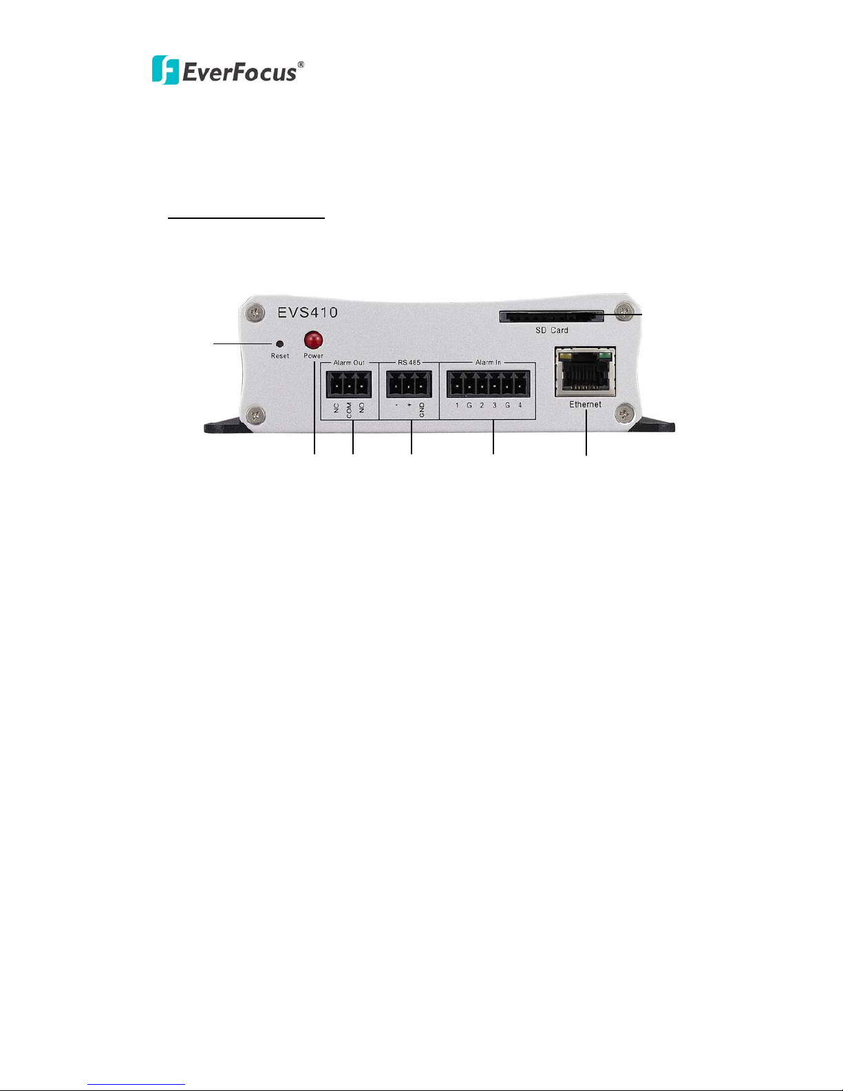
EverFocus EVS410 User manual

EVS410
Installation Guide
Copyright © EverFocus Electronics Corp,
Release: Apr. 2011 Rev.0

EVS410
This installation guide provides instructions for basic wiring of the EVS410 video
encoder. For all other aspects of using this product, please refer to the EVS410 User’s
Manual, which is available on the CD included in this package.
Installation steps
1. Please confirm that all of the accessories have been supplied with the video
encoder as per the list below.
2. Confirm that your PC meets the minimum hardware and software requirements
listed below.
3. Understand the front and rear panel. Please see “Front and Rear panels” on page 4.
4. Network Connection. 3 typical types of network connection. Please see “Network
Connection” on page 6.
5. Set an IP address. Please see “Assign IP address” on page 8.
Package Contents
Please be careful when you unpack the box and the electronic device inside.
Check and make sure that you have all the items listed below inside the original box:
- Video Encoder (x1)
- Mounting Kit to mount the encoder to a wall
- 4 x screws
- 4 x expand screws
- Terminal block connectors
- Alarm in: 1 x 6-pin connector
- Alarm Out: 1 x 3-pin connector
- RS-485: 1x 3-pin connector
- Power adaptor (x1)
- Power cable (x1)
- Printed Installation Guide (x1)
- Software APs including user’s manual CD (x1)
2

EVS410
Minimum Computer Requirements
-CPU: Intel Core2 Duo 2 GHz or higher
-Memory: 1 GB RAM or more
Additional HD space depends on required local storage of video files,
100 Mbps network card
-Screen Resolution: 1024 x 768 pixels or higher, 32-bit pixel color resolution
-Operating system: Microsoft Windows XP, Windows Vista(32bit), Windows 7(32bit)
-Software: DirectX9,0c, Internet Explorer 6.0 or higher
Note: Please connect to Microsoft’s Web Site for downloading.
For example: (This web site may change without notices.)
http://www.microsoft.com/downloads
Dimensions
Top view Front view
3

EVS410
1. Front and Rear Panels
Front Panel Indications
○
7
○
1
○
6
○
2○
5
○
3○
4
○
1Reset: Loading factory default configuration by pressing the button, which
inside this hole. Please insert the keen-edged device to the hole for 5 seconds.
○
2Power: Power LED when power is ON.
○
3Alarm Out: Connect alarm devices to alarm output port of EVS410.
○
4RS485: Connect a PTZ to RS-485 port of EVS410.
○
5Alarm In: Connect alarm input devices to Alarm-in connector.
○
6Ethernet: Ethernet RJ-45 port: Connect to LAN via this standard RJ-45
connector.
Yellow indicator light: On means 100Mbps, Off means 10Mbps.
Green indicator light: On means link, flicking means active, Off means link
fail.
○
7SD Card: Slot to insert SD card.
4

EVS410
Rear Panel Indications
○
1Audio In: Audio input for recording. Connect audio source to audio-in connector.
○
2Audio Out: Connect an audio output signal to other audio device.
○
3Video In (1~4): Analog video input from Camera 1~4.
○
1○
2○
3
○
4
N
ote: Please connect Video In 1 before turn the device ON, then EVS410 will detect
video format automatically.
○
4Power Input: Connect to 12VDC power source.
5

EVS410
2. Network Configuration
This section illustrates connecting different types of network topologies to video
encoder.
a. Router or LAN connection
This is the most common connection that allows multiple users on and off site to see
IP cameras/video encoders on a LAN/WAN through a router. The video encoder must
be assigned an IP address compatible with the LAN. By setting up port forwarding,
you can view video encoders from outside of the LAN via the Internet or other WAN
connection.
straight through LAN
patch cable
Pinoutofstraightpatchcable
b. Direct High Speed Connection
In a Direct High Speed Connection the video encoder connects directly to modem
without a router. You need to set the WAN IP address assigned by the Internet service
provider (static or DHCP) in the IP camera/Encoder. To access the video encoder,
just type http:// IP address from your Internet provider. If you have a dynamic IP
address, this connection may require that you use DDNS for a reliable connection.
Please see User Manual Section 4.3.2.
6

EVS410
Pinout of straight patch cable
c. One to one connection from PC to video encoder
You can connect directly without switch. However, only the PC connecting to device
can view the video encoder; it will be necessary to manually assign compatible IP
addresses to both devices; and, unless the PC has another network connection, the
video encoder will be the only network device visible to the PC.
Pinout of straight patch cable Pinout of crossover-cable
7

EVS410
3. Assign IP Address
Please install the IP utility software from the CD before you go through the following
process. Please note the following procedures are an example according to EVS410
default values. These values may vary with your network system. Please consult your
ISP or network administrators for the proper settings for your network environment.
IP utility (on the supplied CD) is the recommended tool to assign and IP address. The
default network setting for the video encoder is DHCP. Once you access the video
encoder, you can change the TCP/IP settings for your own network environment.
1. Launch the IP Utility.
2. Click the “Find Devices” button.
This proves the connection to the device and displays the device network configuration
details including Mac Address, Machine Name, IP Address, IP Type, Subnet Mask,
Gateway Address, DNS1 Address, DNS2 Address, Port, Status and Progress.
The information for all the devices found will be automatically detected and shown in
the window. Select/click on the desired device.
8

EVS410
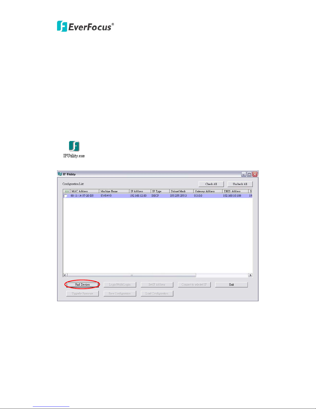
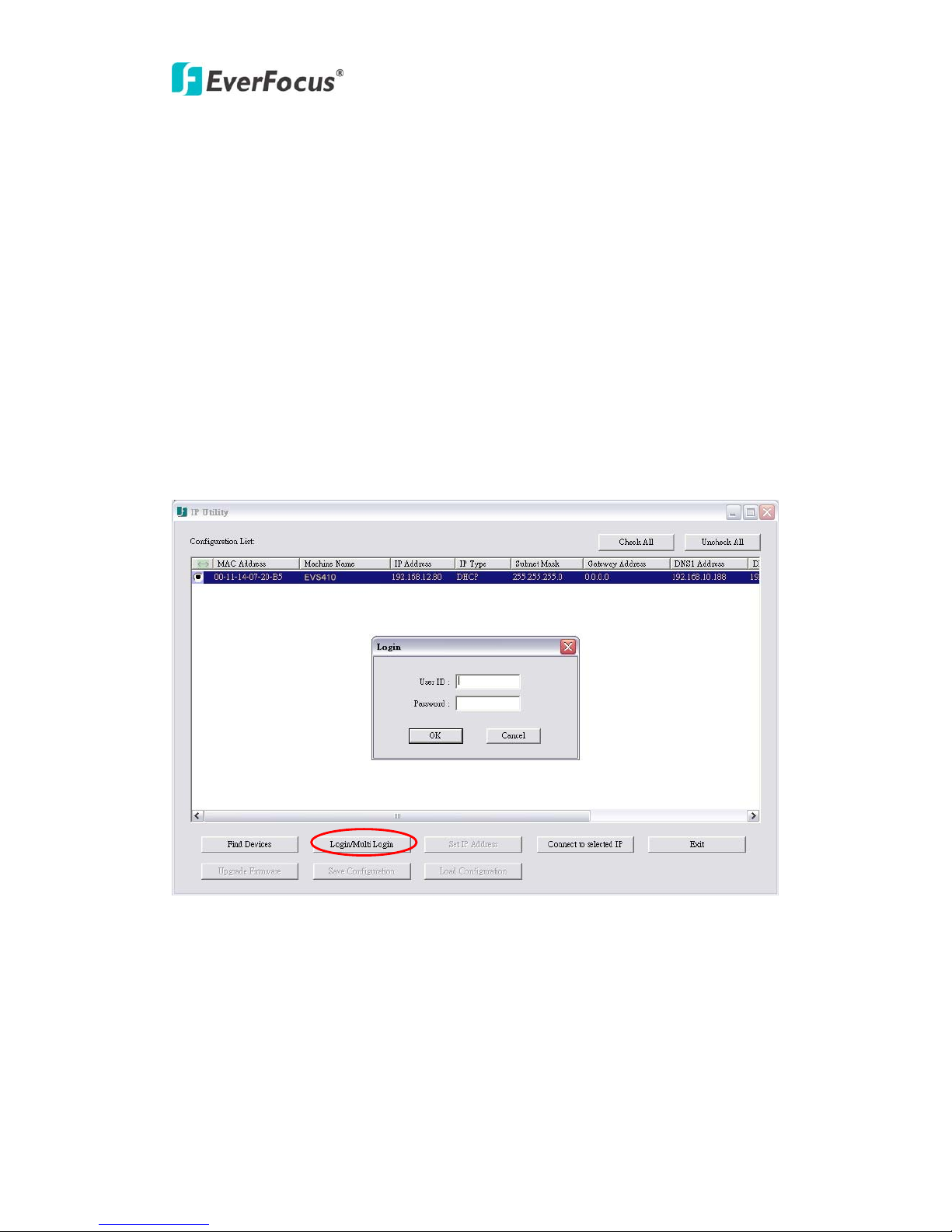
3. In order to manually configure the IP settings or upgrade firmware or save/load
configuration, YOU MUST CLICK “Login/Multi Login”. If selecting more than 1
device that has same user name/password, you will be able to login several devices.
This will bring up a dialog box where you will be asked to enter “User ID” and
“Password”. This part of the security model; only a user with Supervisor or
Administrator level rights can modify the network configuration of the device. The ID
& password entered must be at least administrator level; this ID and password will be
used for all configuration changes made during this process. If the ID and password
do not have at least administrator level rights, then any changes will be discarded.
Press “Find Devices” button to refresh the login status. It will make the devices
logout.
Note: Default User ID is “user1” and default password is “11111111”. This ID has
Supervisor level rights.
4. To change IP settings, select the device with highlight bar then double click on the
value that you wish to revise and enter the desired new value. After the change is done,
press “Set IPAddress” to write the new setting to the device.
Note: While most networks support DHCP, when you are unsure of the type to use,
please consult your IP administrator for the network configuration details.
9

EVS410
. To upgrade firmware, select the device with highlight bar to do firmware upgrade.5
The window pops up after clicking the “Firmware Update” button. Select and Open
the firmware file (.evb) to execute firmware update.
10

EVS410
After opening the firmware file, the progress is running. Once updating firmware is
n
completed, the device will reboot. Click “Search devices” again, the firmware versio
will change to the new one. If system is rebooting, IP utility cannot find the device.
Note: During firmware update, all connection and activities will be disabled automatically.
6e “Save Configuration” or “Load
you open
. The window pops up after clicking th
configuration” button. The configuration files will be saved under the path
or Save the select configuration file to the selected devices.
11

EVS410
7. To copy / paste IP Settings, right click the selected device which has been login,
press “Copy” or “Paste” to copy/paste IP settings included IP type, Subnet Mask,
Gateway Address, DNS1 Address, DNS2 Address and Port.
8. To view a device, select it with highlight bar and click “Connect to selected IP” and
e web browser will automatically be launched and connect to the device.
th
12

EVS410
9. You will be asked to enter User ID and Password first in order to access the video
encoder.
1video
encoder.
Note: Default user name is “user1” and default password is “11111111”.
0. After login, the browser window will display the LIVE VIEW page of the
11. Exit: When you are finished, the EXIT button will close the IP Utility.
13

EVS410
EverFocus Electronics Corp.
Ever in-Tai Wu Road,
m.tw
Focus Taiwan:
14
12F, No.79, Sec. 1, Sh
Hsi-Chih, Taipei, Taiwan
TEL: +886 2 2698 2334
FAX: +886 2 2698 2380
www.everfocus.com.tw
marketing@everfocus.co
EverFocus Europe - Germany: 6
Albert-Einstein-Strasse 1, D-4644
Emmerich, Germany
TEL: +49 2822 93940
FAX: +49 2822 939495
www.everfocus.de
EverFocus China - Beijing:
Room 609, Technology Trade Building,
a
m.cn
Shangdi Information Industry Base,
Haidian District, Beijing 100085, Chin
TEL: +86 10 6297 3336~39
FAX: +86 10 6297 1423
www.everfocus.com.cn
marketing@everfocus.co
zhen: ng hina
m.cn
EverFocus China - Shen
4F, No. 2, D4 Building, Wan Yelo
Industrial Park, Tangtou Road, Shiyan,
Baoan, Shenzhen, Guangdong 518101, C
TEL: +86 755 2765 1313
FAX: +86 755 2765 0337
www.everfocus.com.cn
marketing@everfocus.co
uarte, CA 91010, USA
EverFocus USA- California:
1801 Highland Avenue, Unit A, D
TEL: +1 626 844 8888
FAX: +1 626 844 8838
www.everfocus.com
pauge, NY 11788, USA
EverFocus USA- New York:
415 Oser Avenue, Unit S, Haup
TEL: +1 631 436 5070
FAX: +1 631 436 5027
www.everfocus.com
uilding, 2-13-4 022, Japan
EverFocus Japan:
5F, Kinshicho City B
Koto-Bashi,Sumida-Ku, Tokyo, 130-0
TEL: +81 3 5625 8188
FAX: +81 3 5625 8189
www.everfocus.co.jp
EverFocus Europe - UK: ark, 0 4WD, UK
Unit 12, Spitfire Business P
Hawker Road, Croydon Surrey, CR
TEL: +44 20 8649 9757 / +44 845 430 9999
FAX: +44 20 8649 9907
www.everfocusuk.co.uk
EverFocus India:
Suite 803, Housefin Bhavan, C-21, Bandra Kurla
Complex, Bandra (East), Mumbai 400051, India
TEL: +91 22 6128 8700
FAX: +91 22 6128 8705
www.everfocus.in
Y
our EverFocus product is desi
g
ned
and manufactured with high quality
materials and components which can
osed of
nt at
uropean Union there are
ct.
e
Ihr EverFocus Produkt wurde entwickelt
und hergestellt mit qualitativ
hochwertigen Materialien und
m n
stelle oder im Recycling Centre.
Komponenten, die recycelt und wieder
verwendet werden können.
Dieses Symbol bedeutet, dass
elektrische und elektronische Geräte am
Ende ihrer Nutzungsdauer vo
be recycled and reused.
This symbol means that electrical and
electronic equipment, at their
end-of-life, should be disp
separately from your household waste.
Please, dispose of this equipme
your local community waste
collection/recycling centre.
In the E
separate collection systems for used
electrical and electronic produ
Please, help us to conserve th
Hausmüll getrennt entsorgt werde
sollen.
Bitte entsorgen Sie dieses Gerät bei
Ihrer örtlichen kommunalen
Sammel
Helfen Sie uns bitte, die Umwelt zu
erhalten, in der wir leben!
environment we live in!
P/N: 4605PEVS04B010A
Other manuals for EVS410
1
Table of contents
Other EverFocus Media Converter manuals

EverFocus
EverFocus EVS200A User manual

EverFocus
EverFocus EHA-SRX User manual

EverFocus
EverFocus EverPlex 4BQ User manual

EverFocus
EverFocus EMX32 User manual

EverFocus
EverFocus EMX32 User manual

EverFocus
EverFocus EVS200AW-W User manual

EverFocus
EverFocus EMX32 User manual

EverFocus
EverFocus EP4CQ FHD User manual

EverFocus
EverFocus EHA-CRX User manual