IndigoVision 9000 Series User manual

IndigoVision
Dual Channel Encoder
9000 Range
User Guide

2 User Guide - v8
THIS MANUAL WAS CREATED ON 02 SEPTEMBER 2015.
DOCUMENT ID: IU-BOX-MAN004-8
Legal considerations
LAWS THAT CAN VARY FROM COUNTRY TO COUNTRY MAY PROHIBIT CAMERA SURVEILLANCE. PLEASE ENSURE THAT THE RELEVANT LAWS
ARE FULLY UNDERSTOOD FOR THE PARTICULAR COUNTRY OR REGION IN WHICH YOU WILL BE OPERATING THIS EQUIPMENT. INDIGOVISION
LTD.ACCEPTS NO LIABILITY FOR IMPROPER OR ILLEGAL USE OF THIS PRODUCT.
Copyright
COPYRIGHT © INDIGOVISION LIMITED. ALL RIGHTS RESERVED.
THIS MANUAL IS PROTECTED BY NATIONAL AND INTERNATIONAL COPYRIGHT AND OTHER LAWS. UNAUTHORIZED STORAGE,REPRODUCTION,
TRANSMISSION AND/OR DISTRIBUTION OF THIS MANUAL,OR ANY PART OF IT,MAY RESULT IN CIVIL AND/OR CRIMINAL PROCEEDINGS.
INDIGOVISION IS A TRADEMARK OF INDIGOVISION LIMITED AND IS REGISTERED IN CERTAIN COUNTRIES. SMS4, C AMERA GATEWAY ,AND
MOBILE CENTER ARE UNREGISTERED TRADEMARKS OF INDIGOVISION LIMITED. ALL OTHER PRODUCT NAMES REFERRED TO IN THIS MANUAL
ARE TRADEMARKS OF THEIR RESPECTIVE OWNERS.
SAVE AS OTHERWISE AGREED WITH INDIGO VISION LIMITED AND/OR INDIGO VISION, INC., THIS MANUAL IS PROVIDED WITHOUT EXPRESS
REPRESENTATION AND/OR WARRANTY OF ANY KIND. TO THE FULLEST EXTENT PERMITTED BY APPLICABLE LAWS , INDIGO VISION LIMITED
AND INDIGO VISION, INC.DISCLAIM ALL IMPLIED REPRESENTATIONS ,WARRANTIES ,CONDITIONS AND/OR OBLIGATIONS OF EVERY KIND IN
RESPECT OF THIS MANUAL. ACCORDINGLY,SAVE AS OTHERWISE AGREED WITH INDIGO VISION LIMITED AND/OR INDIGOVISION, INC., THIS
MANUAL IS PROVIDED ON AN “AS IS”, “WITH ALL FAULTS”AND “AS AVAILABLE”BASIS. PLEASE CONTACT INDIGOVISION LIMITED (EITHER BY
POST OR BY E-MAIL AT PARTNER.SUPPORT@INDIGOVISION.COM )WITH ANY SUGGESTED CORRECTIONS AND/OR IMPROVEMENTS TO THIS
MANUAL.
SAVE AS OTHERWISE AGREED WITH INDIGO VISION LIMITED AND/OR INDIGO VISION, INC., THE LIABILITY OF INDIGOVISION LIMITED AND
INDIGOVISION, INC.FOR ANY LOSS (OTHER THAN DEATH OR PERSONAL INJURY)ARISING AS A RESULT OF ANY NEGLIGENT ACT OR OMISSION
BY INDIGO VISION LIMITED AND/OR INDIGO VISION , INC.IN CONNECTION WITH THIS MANUAL AND/OR AS A RESULT OF ANY USE OF OR
RELIANCE ON THIS MANUAL IS EXCLUDED TO THE FULLEST EXTENT PERMITTED BY APPLICABLE LAWS.
Contact address
IndigoVision Limited
Charles Darwin House,
The Edinburgh Technopole,
Edinburgh,
EH26 0PY
Dual Channel Encoder - 9000 Range

User Guide - v8 3
TABLE OF CONTENTS
Legal considerations 2
Copyright 2
Contact address 2
1 About This Guide 5
Safety notices 5
2 Hardware Description 7
Overview 7
Dual Channel Encoder 8
Connections 8
Composite video input 9
S-Video input 9
Audio In 9
Audio Out 9
Network 10
Console port 10
Data port 10
Terminal block 11
Indicator LEDs 12
Power requirements 13
Power consumption 13
3 Getting Started 15
Package contents 15
Dual Channel Encoder 15
Powering the device 16
Auxiliary power supply 16
Extended Temperature variant 16
Initial configuration 16
Initial IP properties 16
Using the configuration pages 17
Using the serial port connection 20
Attaching the device to the network 21
4 Installation 23
Connecting a video source, binary IO and audio 23
5 Operations 25
Setting up a common serial data connection for PTZ control 25
Using the serial port as an RS232 data port 25

4 User Guide - v8
6 Configuration 27
Web Configuration pages 27
Home 27
Network 27
Date & Time 28
Video 29
Profiles (Transmitters only) 29
Encoder 30
Analytics 31
Audio 34
PTZ (Serial) 34
Binary Input/Output 35
Events 36
Advanced Network Configuration 36
Network Security 37
Advanced Network Security 39
Firmware Upgrade 40
Diagnostics 40
Enabling and disabling web configuration 40
Resetting to factory defaults 41
Bulk Configuration 41
Dual channel device rules 44
7 Hardware Specification 45
Codec specifications 45
Video 45
Video codec 45
Resolution 45
Audio 45
Streaming specification 45
Audio In 46
Audio Out 46
Data input/output 46
Data port 46
Console/Data port 46
Network connections 46
Binary input 46
Binary output 47
SMS requirements 47
Environment 47
Regulatory 47
Dual Channel Encoder - 9000 Range

User Guide - v8 5
1ABOUT THIS GUIDE
This guide is written for users of the IndigoVision Dual Channel Encoder. It provides
installation and configuration information for the device variants, as well as a description of
the hardware and specifications.
Please ensure you read the instructions provided in the guide before using the device.
Safety notices
This guide uses the following formats for safety notices:
Indicates a hazardous situation which, if not avoided, could result in death or serious injury.
Indicates a hazardous situation which, if not avoided, could result in moderate injury, damage
the product, or lead to loss of data.
Indicates a hazardous situation which, if not avoided, may seriously impair operations.
Additional information relating to the current section.

6 User Guide - v8
1 About This Guide Dual Channel Encoder - 9000 Range

User Guide - v8 7
2HARDWARE DESCRIPTION
This chapter details the Dual Channel Encoder, its connections, and its weights and
dimensions.
Overview
The IndigoVision Dual Channel Encoder is a standalone encoder designed to be used with
the company’s complete end-to-end IP Video solution. It provides class- leading H.264
compression technology, and is ONVIF conformant, providing an open standards solution
while retaining the resilience of IndigoVision’s distributed architecture, with no bottle necks
and no single-point-of-failure.
The device encodes video, audio, and binary events allowing traditional analog CCTV
cameras (PALand NTSC) to be integrated into an IP network.
The Dual Channel Encoder is available in the following variants:
• Standard Temperature
Operating temperature: 0°C to +45°C (32°F to 113°F)
• Extended Temperature
Operating temperature: -30°C to +55°C (-22°F to 131°F)
Includes heater and fan
When operating as a single channel encoder, the maximum operating temperature of the
Extended Temperature model is increased to 65°C.
8 User Guide - v8
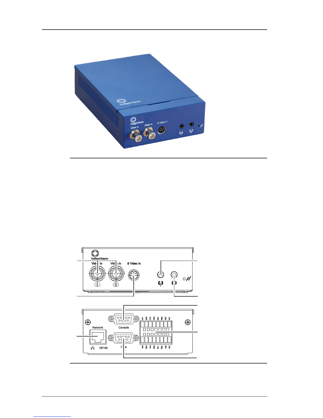
Dual Channel Encoder
Figure 1: Dual Channel Encoder
Dimensions
• 169mm (l) x 123mm (w) x 44mm (d)
Weight
• 0.6Kg (excluding power supply)
Connections
There are connections on both the front and rear of the device.
1
2
3
4
5
7
8
6
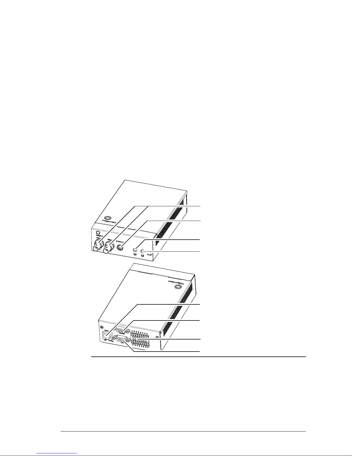
Figure 2: Connections - front and rear
1. 2x Composite Video In
2 Hardware Description Dual Channel Encoder - 9000 Range

User Guide - v8 9
2. S-Video In
3. Network
4. Audio In
5. Audio Out
6. Console Port
7. Terminal Block
8. Data Port
Composite video input
The video connectors of the device are standard 75 Ohm terminated BNC connectors. The
input format is composite video on these connectors.
Use input 1 for the primary channel and input 2 for the secondary channel.
When using the S-Video input, Composite Video input 1 is not available.
S-Video input
For sources which support S-Video, IndigoVision recommends that you use the S-Video input
to achieve high quality video at lower bitrates.
S-Video is only available on the primary channel.
Table 1: S-Video connector pin numbering
1Y GND
2C GND
3Y (LUMA)
4C (CHROMA)
When using the S-Video input, Composite Video input 1 is not available.
Audio In
The Audio In is a mono input, 3.5mm jack (stereo type) and supports an input signal
amplitude of up to 1V p-p. The audio input gain of the device can be adjusted from the audio
web page to cater for lower input signal amplitudes.
The audio input for the primary channel (channel 1) is delivered on the tip, and the audio input
for the secondary channel (channel 2) is delivered on the ring. The ground (GND) connection
for both channels is on the sleeve.
Audio Out
The Audio Out is a 3.5mm jack and provides an output signal amplitude of up to 1V p-p. This
output is not capable of driving a speaker directly. It should be connected to a suitable
Dual Channel Encoder - 9000 Range 2 Hardware Description

10 User Guide - v8
amplifier, powered speakers or headphones. The minimum load impedance rating of this
output is 16 Ohms.
The audio output for the primary channel (channel 1) is delivered on the tip, and the audio
output for the secondary channel (channel 2) is delivered on the ring. The ground (GND)
connection for both channels is on the sleeve.
Network
The network connector is an RJ45 connector. It is auto-sensing 10/100 Base-T Ethernet
• Maximum length: 100m
• CAT5 cables or higher
Console port
The Console port is a standard RS232 serial connection with a 9-pin DSub connector.
►For more information about configuring the device using this port, see "Using the serial
port connection" on page 20.
This port can also be used as a secondary data port.
►For more information, see "Using the serial port as an RS232 data port" on page 25
Table 2: Console port pin numbering
Pin RS232 Function
1 NC
2 Rx
3 Tx
4 NC
5 GND
6 NC
7 NC
8 NC
9 NC
Data port
The Data port is an RS485/422 port with a 9-pin DSub connector.
The device supports other RS485 devices in a point-to-point configuration only.
Table 3: Data port pin numbering
Pin RS485/422 Function
1
2 Rx-
3 Tx-
2 Hardware Description Dual Channel Encoder - 9000 Range
User Guide - v8 11
Pin RS485/422 Function
4
5 GND
6
7 Tx+
8 Rx+
9
Terminal block
The terminal block provides connector pins for the binary inputs and outputs, as well as the
power supply.
►For more information, see "Powering the device" on page 16
There are four binary inputs, and two binary outputs.
Name Description
IN1-2 Binary Input 1-2 (Primary channel)
IN3-4 Binary Input 3-4 (Secondary channel)
RA1 RA2 Binary Output Relay 1 (Primary channel)
RB1 RB2 Binary Output Relay 2 (Secondary channel)
GND GND
AUX +24V AC/DC Auxiliary Power
NC Not Connected (Standard)
HTR +24V AC/DC Heater Power (Extended Temp.)
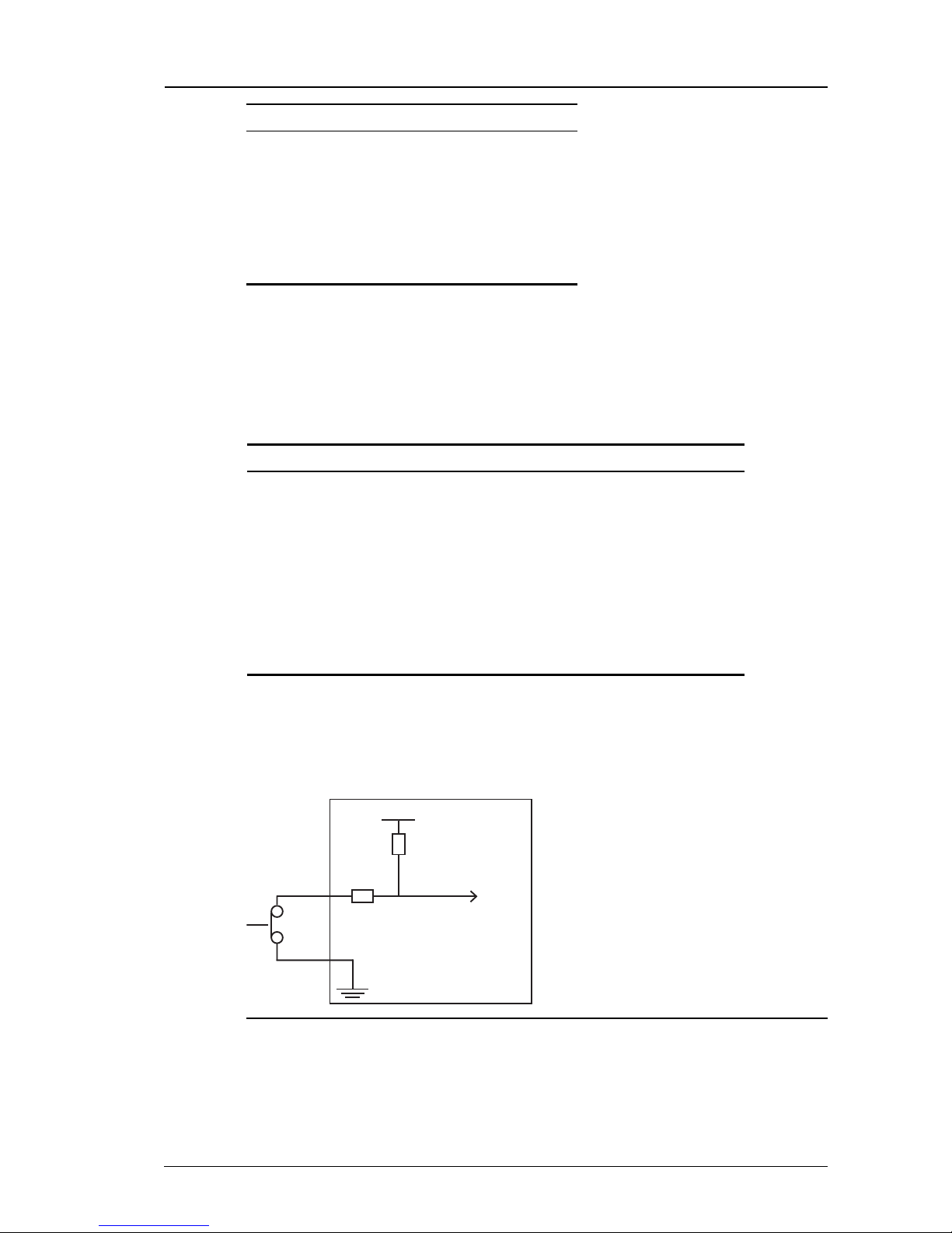
Binary input
The binary inputs allow you to connect external trigger sources to the device. The pins
provide pull-up inputs that are normally in the high state. To change the state, ground the input
pin as shown in Figure 3: on page 11.
1.8V
Input
10K
470
Protected to 24V
Figure 3: Example binary input - low state
For input voltages greater than 24V DC, an external resistor is required in series with the input
pin.
Dual Channel Encoder - 9000 Range 2 Hardware Description

12 User Guide - v8
1.8V
48V Input
10K
47010K
Figure 4: Binary input for voltages greater than 24V DC
►For more information, see "Binary input" on page 46
Input voltages above 50Vpk at Vin will irrevocably damage the device.
Binary output
Binary output pins are controlled by your software applications. These pins are electronically
switched and are either open-circuit or closed.
When closed, the effective resistance between Rx 1 and Rx 2 is not greater than 4Ω.
External
device
Supply
Rx1
Rx2
Figure 5: Example binary output
►For more information, see "Binary output" on page 47
Indicator LEDs
When the device is powered up, the LEDs indicate the activity and status as described in on
page 12.
Name Image Color Status Meaning
Activity Green Flashing Device is operating normally
Solid on/off System failure
10/100 10/100 Green On 100Base-TX mode
Off 10Base-T mode
Link Amber Flashing Link is up and there is network traffic
On Link is up, but there is no network traffic
Off Link is down
2 Hardware Description Dual Channel Encoder - 9000 Range

User Guide - v8 13
Power requirements
The Dual Channel Encoder can be powered by the following methods:
• Power over Ethernet (PoE): 802.3af
• Auxiliary power
• 24V DC (+10%/-30%)
• 24V AC
►For more information, see "Powering the device" on page 16
The Extended Temperature variant additionally has a 24V AC/DC input to power a heater.
Power supplies are orderable separately from IndigoVision.
Power consumption
• Standard Temperature variant: 6W max
• Extended Temperature variant: 6W max
• Heater: 30W max
Dual Channel Encoder - 9000 Range 2 Hardware Description

14 User Guide - v8
2 Hardware Description Dual Channel Encoder - 9000 Range
User Guide - v8 15
3GETTING STARTED
This chapter describes the initial steps required to start using your Dual Channel Encoder.
Package contents
Before continuing, please check that you have been shipped the items listed for your device.
Dual Channel Encoder
4
2
3
5
1
6
7
8
Figure 6: Standard variant package contents
1. 2x Composite Video In
2. S-Video In
3. Audio In
4. Audio Out
5. Network
6. Console Port

16 User Guide - v8
7. Terminal Block
8. Data Port
Powering the device
The device is Power over Ethernet (PoE) powered and is compliant with the IEEE802.3af
(Class 0) standard.
There are a number of methods of powering up a device:
• Power over Ethernet (PoE) switch
• PoE injector/midspan
• Auxiliary power
The Extended Temperature variant requires an additional 24V AC/DC power supply to power
the internal heater for operations down to -30°C (-22°F).
Auxiliary power supply
The auxiliary power (max power 6W) is provided via the two AUX pins of the Binary I/O
connector on the rear of the device.
►For more information, see "Terminal block" on page 11
Extended Temperature variant
The Extended Temperature Variant requires an additional 24V AC/DCpower supply to power
the internal heater for operations down to -30°C (-22°F).
The 24V AC/DCpower (max power 30W) is provided via the two HTRpins on the Binary I/O
connector on the rear of the device.
►For more information, see "Terminal block" on page 11
Initial configuration
You can configure your device using the Configuration pages or the console port.
Initial IP properties
Each device is assigned two IP addresses, one for each channel. The primary IP address is
used to configure system settings for both channels.
The following table displays the initial, default IP properties for the device.
Table 4: Initial IP properties
Initial Configuration
Primary Channel IP Address 10.5.1.10
Secondary Channel IP Address 10.5.1.11
Subnet Mask 255.0.0.0
Default Gateway 10.0.0.1
3 Getting Started Dual Channel Encoder - 9000 Range
User Guide - v8 17
Using the configuration pages
To configure your device using the Configuration pages you must do the following:
1. Prepare an isolated network.
2. Prepare your PC for initial device configuration.
3. Configure your device. This includes specifying its IP address and subnet mask.
You must also have one of the following:
• A CAT5 crossover cable suitable for connection between the PC and the RJ45
connector on the device
• A power source
• 24V PSU
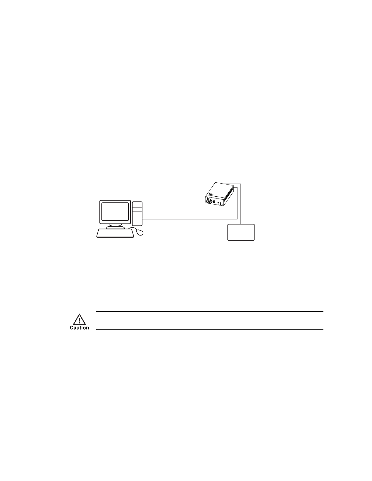
Preparing an isolated network
Connect your device and the PC you are using to configure it on their own isolated network.
To do this, connect the device to the PC using an Ethernet cross-over cable.
Power Supply
(not required
for PoE)
PC
Encoder
Cat5 Crossover
cable
Figure 7: Connecting the device and PC using a cross-over cable
Preparing for initial device configuration
You cannot connect the device to your network until you have changed the IP settings to suit
your network.
To change the factory defaults of your device, you must first, temporarily, modify your PC’s
network settings.
Make a note of the original value of all settings that are to be changed so that you can re-enter
them when you have completed the initial device configuration.
To change your PC’s settings, use the Windows Network Settings configuration application
to set the PC’s IP address and subnet mask.
1. Open Control Panel >Network and Sharing Center >Change adapter settings.
2. Right-click Local Area Connection and select Properties.
3. Select Internet Protocol Version 4 (TCP/IPv4) and click Properties.
4. Set the IP address to an address close to the factory IP address, for example,
10.5.1.2, and change the PC’s subnet mask to 255.0.0.0 (the same as the
factory default).
5. Click OK, then OK again to save the changes.
Dual Channel Encoder - 9000 Range 3 Getting Started

18 User Guide - v8
Configure the device
Once you have changed your PC’s network settings, you can change the IP settings of the
device from the factory defaults.
On dual channel devices the IPproperties are configured on the primary channel. The primary
and secondary channel must have the same subnet mask and gateway, but unique
IPaddresses.
To change these values:
1. Open the Internet Explorer application.
2. Enter 10.5.1.10 (the factory default IP address) into the browser address bar, then
click OK.
The Configuration Home page opens.
3. Click the Network link on the left of the page.
4. Configure the network parameters for the device to suit your installation.
IndigoVision recommends that you make a note of the new IP address and subnet mask.
•Host Name — Enter a name for the device to identify it. The name can only contain
alphanumerical characters and hyphens.
•Location — Enter a location to identify the device. The location can only contain
alphanumerical characters and hyphens.
•IP Address — Enter the IP address of the device.
•Subnet Mask — Enter the IP network subnet mask.
Ensure that you enter the correct values. Once you change from the defaults, the device is no
longer configurable by the PC with its current network settings.
•Gateway — This is the appropriate default gateway for remote network access and is
only required if the devices are to be accessed from a different subnet.
•DNS Server 1 & 2 — Enter the IPaddress of a primary (1) and secondary (2)
DNSserver if required.
•DNS Domain — Specify the DNSdomain the device will use.
•NTP Server Address — Address of NTP time server (update this setting on the Date
& Time page).
•Ethernet Interface — Enter a link type. The values are as follows:
• 10Mbps Half-Duplex
• 100Mbps Half-Duplex
• 10Mbps Full-Duplex
• 100Mbps Full-Duplex
• Auto-negotiate
You may need to change the Ethernet link type default value from Auto-negotiate for
some network devices. If you have problems maintaining a network link, contact your
system administrator to determine the appropriate setting.
3 Getting Started Dual Channel Encoder - 9000 Range

User Guide - v8 19
This setting must match the setting on the switch port that is connected to. Otherwise, poor
network performance may be experienced.
Ensure that you enter the correct values. Once you change from the defaults, no further
configuration changes can be made from the PC with its current network settings.
If your network uses a DHCP server, select Use DHCP to allow the DHCP server to
assign the following parameters:
• IP Address
• Subnet Mask
• Default Gateway
• Hostname
• Network Time Server Address (if enabled on the Date & Time page)
IndigoVision recommends that if you are using DHCP, you should configure the DHCP
server to assign a given IP address based on MAC address. If no response is received from
the DHCP server it will default to using the network parameters supplied by the last
completed DHCP request.
When you have entered the configuration data, click Submit to apply the changes.
5. To configure another device, disconnect the network cable leaving it connected to the
PC.
6. Connect the network cable to the next device you want to configure.
Before you can access the next device for configuration, you must type the following
command from a Command Window:
C:> arp -d 10.5.1.10
7. Repeat these steps for each device, using different IP addresses for each.
Ensure that the same IP address is not used more than once, including on the PC. Contact
your network administrator if you require further assistance.
When you have configured all your devices, return the PC to its original settings, or change
them as appropriate for your network.
You are now ready to take your device(s) off the isolated network and connect them to the
main network, and install the Dual Channel Encoder.
If required, you can reset the IP values back to their defaults.
►For more information, see "Resetting to factory defaults" on page 41
Dual Channel Encoder - 9000 Range 3 Getting Started

20 User Guide - v8
Using the serial port connection
1. Connect a standard RS232 null modem serial cable to the Dual Channel Encoder.
Power
(Aux PSU
or PoE)
configuration software
PC with serial
Serial cable
Encoder
Figure 8: Serial port connection
2. On the PC, use a Terminal Emulation program such as Windows HyperTerminal and
set the serial port parameters as follows:
• 115200 baud
• 8 bits
• No parity
• 1 stop bit
• Flow Control: None
3. Connect to the device and press Enter. You should see a login prompt.
4. Log in to the device using the username "config" and password "config". The
device prompts you to enter the new configuration values. At each prompt, press
Enter to accept the current value.
•Use DHCP (y/n) — Enter yto use DHCP for IP configuration, or nfor manual IP
configuration.
On dual input devices, DHCP assigns an IPaddress to the primary channel only.
You need to manually assign an IPaddress to the secondary channel.
•IP Address — Enter the IP address for each channel of the device.
•Subnet Mask — Enter the IP network subnet mask.
•Default Gateway — Enter the appropriate default gateway for remote network
access.
This is only required if the device is to be accessed from a different subnet.
•Host name — Enter a name to describe the device.
The name can only contain alphanumeric characters and hyphens.
•Location — Enter a name to describe the location of the device.
The location can only contain alphanumeric characters and hyphens.
•Link type — Enter a link type.
The values are as follows:
Select: 0 - 100Mbps Half-Duplex.
Select: 1 - 100Mbps Full-Duplex.
Select: 2 - 10Mbps Half-Duplex
Select: 3 - 10Mbps Full-Duplex
Select: 4 - Auto-negotiate
3 Getting Started Dual Channel Encoder - 9000 Range
Table of contents
Other IndigoVision Media Converter manuals


