Fortex RF100 User manual

Fortex Engineering Ltd, Unit 16, Freeman Road, Lincoln, LN6 9AP, United Kingdom
www.fortex.co.uk s[email protected] +44(0)1522 718 168
RF100 CONVECTION REFLOW
OVEN

Fortex Engineering Ltd, Unit 16, Freeman Road, Lincoln, LN6 9AP, United Kingdom
www.fortex.co.uk s[email protected] +44(0)1522 718 168
Tabel of Content
Prospect .................................................................................................................................... 3
Technical Data ............................................................................................................................. 3
Intended Use of Machine .......................................................................................................... 4
Safety Regulations .................................................................................................................... 4
Scope of delivery ....................................................................................................................... 6
Installation ................................................................................................................................. 6
Overview ................................................................................................................................... 7
Description of the function keys ................................................................................................. 7
The temperature curve ............................................................................................................. 8
Setting of Parameters ................................................................................................................ 9
Reflow-Process ....................................................................................................................... 12
Characteristics of soldering alloys ........................................................................................... 13
Temperature curve parameters ................................................................................................ 14
Cleaning and Maintenance ...................................................................................................... 14
Error message ......................................................................................................................... 15
Spare Parts and Options ......................................................................................................... 15
Guarantee ............................................................................................................................... 15
Disclaimer of Warranty ............................................................................................................ 15
Copyright ................................................................................................................................. 16

Fortex Engineering Ltd, Unit 16, Freeman Road, Lincoln, LN6 9AP, United Kingdom
www.fortex.co.uk s[email protected] +44(0)1522 718 168
Prospect
The RF100 is a stylish, practical reflow oven for manufacturing and reworking of SMT
products. The oven has a large display. The intuitive menu navigation is controlled by a
membrane keyboard. The product uses highly efficient infrared heating elements and has
several thermocouple temperature gauges. Due to this and the precise evaluation in the
microprocessor, the temperature curve of the reflow process is highly accurate and the
temperature in the respective reflow sections very uniform.
With the RF100 all common alloys can be processed. The oven has an automatic error
detection with alarm.
This product has a variety of applications such as reflow soldering, repairing, drying and so
on. It is suitable for SMT small series, for research and development of electronic products,
school, education and study. The operating system software is in English.
The stove is well insulated by a special Aluminium silicate cotton, which reduces energy
consumption, protects the circuit and allows optimal operation and keeps the temperature in
the furnace constant.
Technical Data
Power connection 200 – 230 VAC. / 50-60Hz
Max. Power Consumption 2400 W
Max. PCB-Board Size 350 x 300 mm
Time Settings 00:00 – 99:59 sec.
Temperature 60 -300 °C
Setting Options 5 Phases adjustable in time and temperature:
Preheat
Heat
Soldering
Holding
Cool down
Working Mode Automatic Reflow-Soldering
Permanent Heating or Drying function
Option to store 4 different Reflow profiles
Interface Graphic display with Keyboard
automatic Alarm function
Display of Process progress
Heat up Time ca. 8 min
Extraction Sheet metal outer diameter 101,5 mm inner 99,5 mm, internal ventilator with 84
cfm
Dimensions (LxWxH) (mm) 504 x 500 x 314 mm
Weight +/- 28 kg
Technical Changes reserved

Fortex Engineering Ltd, Unit 16, Freeman Road, Lincoln, LN6 9AP, United Kingdom
www.fortex.co.uk s[email protected] +44(0)1522 718 168
Intended Use of Machine
The RF100 is a soldering furnace for SMD components and also designed for lead-free
soldering processes.
All other applications require our written consent or at the user's own risk.
Safety Regulations
IMPORTANT SAFETY INSTRUCTIONS FOR THE FORCED CONVECTION OVEN
Generally
Please read the following text carefully and pay particular attention to the instructions on
safety at work and on commissioning.
Please keep this manual at a safe place. It contains instructions that are also important
for later maintenance or cleaning work.
The machines are not intended for integration or interconnection with other machines or
equipment. They may only be operated in rooms equipped for this purpose and operated
only by qualified specialist personnel (soldering skills). Children and pets are to be kept
away!
Do not use the oven if it is damaged or does not work properly.
Avoid strong shocks and collisions. This could damage the glass heating rods. If the
glass heating elements are damaged, switch off the machine immediately and replace
with original glass heating rods.
Do not run the oven unattended !
Site
The oven must be level and dry and there must be enough space around the oven for
service and maintenance (about 1m on all sides). Do not use this device outdoors! The
table must be able to carry a weight of at least 30 kg. The oven should be used at normal
room temperatures of 15 to 25 degrees.
It is not allowed and even dangerous to install the oven in a cabinet or box. Do not install
this unit near a heating element or stove, even in a damp environment.
Electricity
The machine is manufactured using tested parts according to the usual electrical safety
regulations. However, this does not relieve the user of his duty of care when handling
electrically operated devices.
The main switch disconnects the machine from the power supply. The protection of the
circuit and the fault circuit must be carried out by the customer (13A).
After completion of work, the main switch should always be switched off.
Before carrying out any work on the machine (cleaning, etc.), switch off the machine and
pull out the mains plug. The power outlet should be near the machine and accessible so
that the plug can be pulled quickly in an emergency. This stove must have its own socket,
which may only be used by this stove.
High voltage - the housing may only be opened by qualified persons. High voltages can
cause death or serious injury.
Keep the plug and power cord away from liquid. Avoid liquids entering through the door
or through the ventilation grilles.
Should this nevertheless happen once:
Immediately switch off the oven and unplug the appliance from the socket.
In case of damage, the power cord may only be replaced by qualified persons.

Fortex Engineering Ltd, Unit 16, Freeman Road, Lincoln, LN6 9AP, United Kingdom
www.fortex.co.uk s[email protected] +44(0)1522 718 168
Danger of fire and burns
During operation, the stove becomes hot and it must therefore only be operated under
supervision. Long heating times and high heating temperatures can lead to overheating
of the stove, which in turn may cause fire.
When placing PCBs into the oven or removing them, wear suitable gloves or use
fireproof equipment.
If the stove generates too much smoke, pull the plug and close the door. That stifles the
flames.
Do not place flammable materials in the vicinity or on the reflow oven.
Do not block the ventilation grilles.
Do not touch the cover of the stove, it can be very hot and you risk severe skin burns.
Do not place flammable, explosive or other hazardous substances near the reflow oven.
Do not dry objects that emit flammable and explosive gases!
Never set a temperature higher than 300 ° C! The stove is not designed for that and
could be damaged. We exclude a guarantee for this!
Exhaust
Use the oven only in well-ventilated areas. Follow the safety rules of the solder paste and
adhesive suppliers. During the soldering process gases can arise. These gases may
endanger your health. We recommend the use of a hood or an alternative extractor
option!
1. Check the proper function of the stove using the following checklist:
2. Check the drawer. The drawer must not be kinked or damaged. Do not use the
oven if something is stuck between the lock and the ceiling. If the drawer is
damaged, do not use the oven
3. Check the seal for damage
4. Check if the oven room is free of dents.
5. Check the power cord, plug and socket for damage.
Maintenance
Clean the oven regularly. A dirty stove can lead to dangerous situations.
Do not insert wire or other foreign objects into the air inlet and outlet to avoid burns or
damage to ventilation and heat.
Do not wash the machine directly with water in order not to affect the insulation
performance of the machine.
Note: The oven temperature is measured from the air in the upper area of the heating
compartment. The temperature on the workpiece can vary due to radiation, conduction
and reflection. For sensitive materials, we recommend test runs to determine the optimal
process parameters. Different measuring devices may be recommended.

Fortex Engineering Ltd, Unit 16, Freeman Road, Lincoln, LN6 9AP, United Kingdom
www.fortex.co.uk s[email protected] +44(0)1522 718 168
Scope of delivery
• Reflow-Oven RF100
• Foil tube D100 x 1.5 x 2 m for Exhaust
• Hose clamp
• This manual
Installation
Takeover from transport companies
After receiving and unpacking the machine, check for possible transport damage. In case
of transport damage, please inform your insurance company, the carrier and the
manufacturer / supplier.
Site
The oven must be level and around the machine there must be sufficient space for
operation and maintenance (about 1 m on all sides). When setting up the machine,
observe all safety prevention regulations and other local regulations.
The oven should be set up on a well accessible table. The surface must be level and
heat resistant and be able to carry at least a load of 30 kg.
Install the device near exhaust vent. For the connection between the stove and the vent,
use the supplied Aluminium foil pipe D100.
Make sure the power supply is correctly protected (13A) and residual current protection.
The outlet height of the exhaust air should be about 1m above the machine to use the
chimney effect.
Do not place any other objects on the device, especially no flammable liquids, such as:
As water, hot water, alcohol, methanol, gasoline.
The machine can be cleaned in the cooled state. Wipe the inside of the machine with a
dishcloth. You can use some rinse water or anhydrous alcohol. Do not switch on the
machine until it is completely dry.
At the beginning of operation, odours may occur during operation. This is a normal
phenomenon. After a while, this kind of smell disappears.
When not in use, turn off the main switch and unplug the power cord
If you are not going to use the device for a long time, you should take it out, pack it and
put it back in the original container in order to avoid moisture damage.
If you want to solder small PCB or FPC board pieces, use a high temperature mica
board. Leave at least 30 mm space between the boards on four sides to ensure uniform
heating.
The manufacturer's specifications in the menu are only clues. Use tests to determine the
optimal parameters for your application. Temperature-sensitive precision devices such
as LED, s laser head, micro connectors, soft packages, ICs or similar. Can be soldered
by gently lowering the temperature while lengthening the times.
For components that can withstand high temperatures, you can increase the soldering
temperature accordingly to shorten the reflow soldering time.

Fortex Engineering Ltd, Unit 16, Freeman Road, Lincoln, LN6 9AP, United Kingdom
www.fortex.co.uk s[email protected] +44(0)1522 718 168
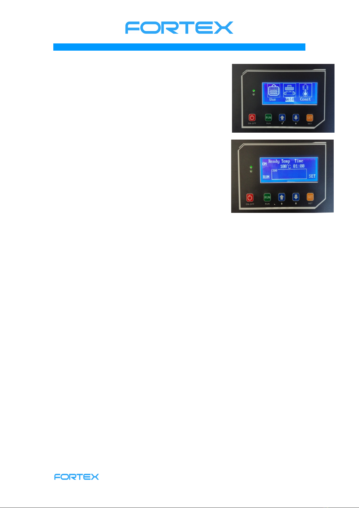
Overview
Description of the function keys
There are 5 buttons on the front panel of the unit: POWER, UP, DOWN, SET, and RUN,
with the RUN and SET buttons being multifunction buttons. Depending on the dialog,
there are various commands above the keys that are activated by pressing the keys.

Fortex Engineering Ltd, Unit 16, Freeman Road, Lincoln, LN6 9AP, United Kingdom
www.fortex.co.uk s[email protected] +44(0)1522 718 168
The temperature curve
In the SMT production process, the temperature curve must be adapted to different alloy
compositions of solder paste. This temperature curve is one of the most important
parameters to ensure product quality. A standard reflow process typically has five
temperature zones. For this reason, you can define 5 temperature zones in the RF100
software to map the standard reflow process.
Each temperature plane with the appropriate temperature and time performs another
function during the soldering process. The requirement and function of each temperature
section are explained below.
Preheating (READY)
Here, the circuit board is heated from room temperature to 120-150°C to remove residual
moisture or residual gas and possibly reduce internal stress in the circuit board. It also
achieves a smooth transition to the next section. The duration is usually 1 - 5 minutes.
The specific time and temperature depends on the size of the board and the number of
components.
Heating up (HEAT)
Here, the preheated circuit board is further heated until the flux contained in the solder
paste becomes liquid. The flux removes oxides of tin paste and component.
Usually the following temperatures are set in this section:
Lead alloy solder and precious metal alloy solder (Sn 42% -Bi58% lead-free or
Sn43% -Pb43% -Bi14% lead containing low-temperature solder)
150 – 180°C
Lead-containing medium temperature solder 180 – 220°C
Lead-free high-temperature solder 220 – 250°C

Fortex Engineering Ltd, Unit 16, Freeman Road, Lincoln, LN6 9AP, United Kingdom
www.fortex.co.uk s[email protected] +44(0)1522 718 168
Soldering (WELD)
Here the reflow process is basically completed. Since the highest temperature is used
here, temperature-sensitive components can easily be damaged. The physical and
chemical changes within the solder paste are the biggest here and the molten solder can
easily oxidise by air in combination with high temperature. The settings of this stage are
based primarily on the data of tin pastes.
Solder pastes are usually classified into low temperature solder pastes (150-180°C),
medium temperature solder pastes (190-220°C) and high temperature solder pastes
(230-260°C).
The lead-free solder used today is a high-temperature solder.
Lead-free low-temperature solder paste usually contains precious metals. Leaded low
temperature solder paste is rarely used and then for special applications. Lead solder
has excellent electrical, physical and mechanical properties, e.g. Temperature change
and oxidation resistance.
In this phase, the solder should be liquid so that the components will float and
automatically center and align with the surface tension of the liquid solder. In addition, 2
intermetallic phases are formed between the circuit board and component, in which the
tin mixes with the copper of the circuit board and the metal of the component and forms
the ideal brazing structure.
The soldering time is usually about 10-30 s. Larger boards and circuit boards with
components that form large soldering shadows require a longer soldering time.
Generally, the soldering time should be kept as long as necessary and as short as
possible so as not to expose the components to unnecessary thermal stress, which can
lead to component malfunction.
Hold time (HOLD)
The holding time plays a role especially for high temperature solders. When high
temperature solder paste rapidly cools, the tin forms very coarse crystals with
undesirable mechanical and physical properties.
At high temperatures and mechanical effects, the welding spots may easily tear off and
lose the mechanical and electrical connection function, thereby reducing the durability of
the product.
By the holding time, the solidification occurs slowly and it form fine crystals.
The temperature is generally set 10-20 ° C lower than the solder melting point.
Cooling time (COOL)
Here the oven is no longer heated and the natural cooling accelerated by a fan. In
principle, you can remove the printed circuit boards when the temperature has fallen
below 150 ° C. Please use tools and personal protective equipment to avoid burns.
Annotation
In general, the soldering temperatures are set as low as possible, so that the
components as well as the printed circuit board are not damaged by thermal stress.
The temperature can also be lowered by extending the reflow time accordingly. This is
advantageous for protecting heat sensitive components, connectors and connectors.
Setting of Parameters
In general, the parameters are set during commissioning and each time the requirements
change due to other materials, components or solder pastes.
Start

Fortex Engineering Ltd, Unit 16, Freeman Road, Lincoln, LN6 9AP, United Kingdom
www.fortex.co.uk s[email protected] +44(0)1522 718 168
Turn on the main power switch on the back of the unit and the indicator light in the upper
left of the screen lights up in green. If you press the red ON-OFF button, the display on
the picture below will show USE, WELD and CONST.
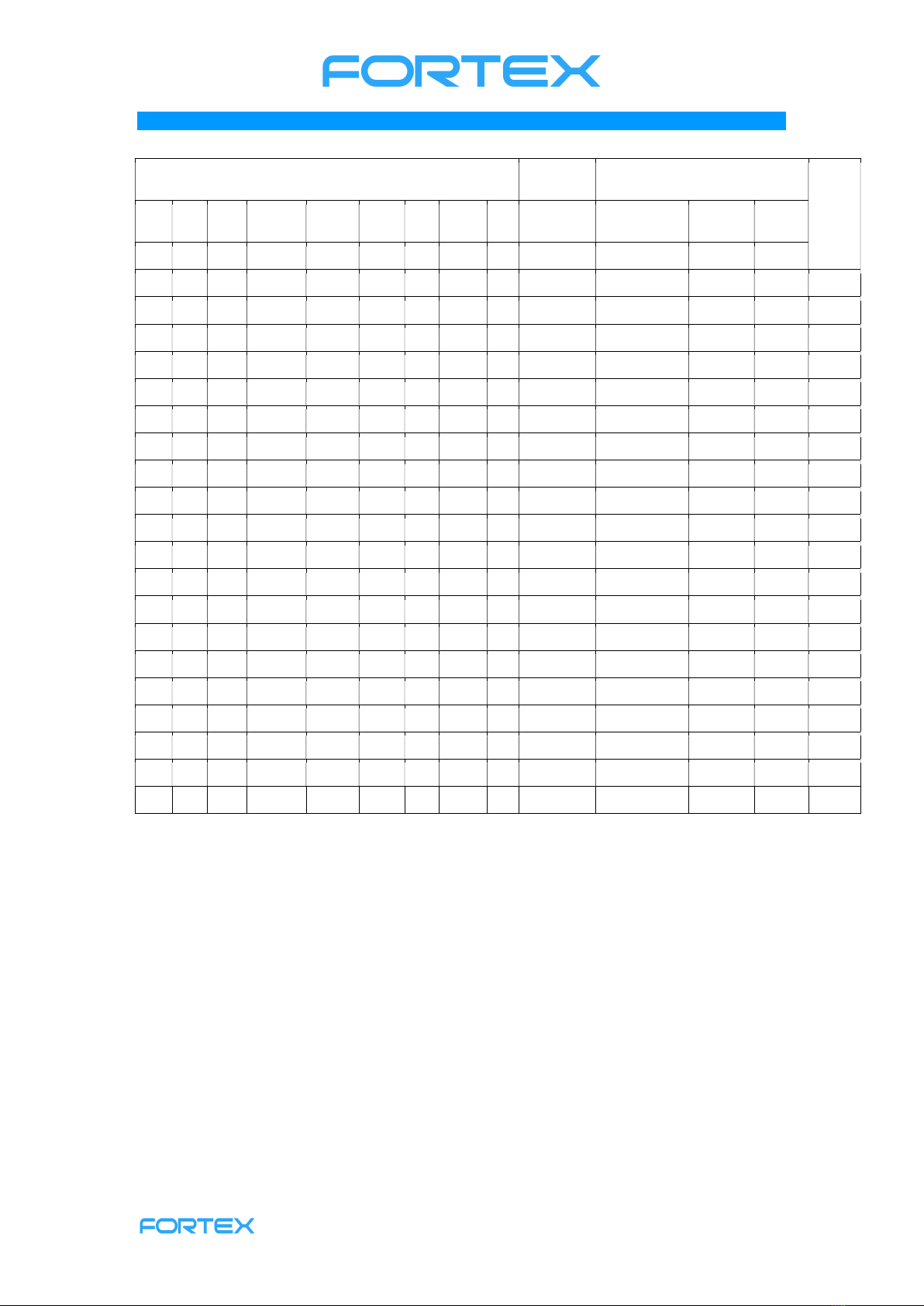
Soldering Mode (WELD)
Preliminary note: the temperature and time settings in the
delivery condition of the stove are only indicative. The
parameters suitable for your application must be determined
by test soldering. Please also refer to the information
provided by the solder paste manufacturer.
After pressing ON-OFF, WELD is highlighted. Press RUN to
display the dialogue as shown in the picture on the left.
RUN starts the cycle, the indicator light in the upper left
corner of the display turns red and the oven starts to heat up.
The soldering cycle will be explained later. Here we first
explain the setting options.
If you press SET instead of RUN, then READY (pre-heat-phase) will be highlighted. Use
the arrow keys to change the text to HEAT, WELD, HOLD or COOL. Stay on READY
and press SET. The marking jumps to TEMP (temperature) and you can adjust the
temperature between 70 and 130°C with the arrow keys. Another press on SET and you
can change the time between 00:00 and 99:99 (minutes: seconds).
Button SET takes you back to READY and here you can use the arrow keys to go e.g. to
HEAT to set the parameters for the heating phase. Press SET to go to the temperature
settings and use the arrow keys to set values between 120 and 300°C. Another SET
takes you to the time setting for the heating phase.
Back to HEAT, press arrow down to get to the actual soldering phase. WELD is marked
and with SET you can change the temperature again between 120 and 300 ° C and set
the time with another SET.
For HOLD, the holding time, the same applies, but the temperatures can only be
adjusted between 70 and 230 ° C here.
When you have finally arrived at COOL, the cooling phase, you can only set the
temperature between 70 and 200 ° C here. A time is not set in section COOL, but a
signal terminates the entire soldering cycle when the set temperature is reached.

Fortex Engineering Ltd, Unit 16, Freeman Road, Lincoln, LN6 9AP, United Kingdom
www.fortex.co.uk s[email protected] +44(0)1522 718 168
To exit the WELD dialogue, press ON-OFF.
Permanent heating mode
In the main menu, you can use the arrow keys to switch
between USE, WELD and CONST. Highlight CONST and
press RUN. The dialogue on the left side appears.
With RUN you switch on the heating, the control light turns
red and the oven heats up to the set temperature (= SET
TEMP). The current temperature is displayed to the left. At the
same time the display changes RUN upwards and STOP
downwards, so that you can end the heating process at any
time by pressing the green RUN button. In this case, RUN
returns to the bottom of the display and STOP to the top and you can restart heating by
pressing the RUN key.
When the set temperature is reached, the indicator changes to green and the oven keeps
the temperature.
Saving custom temperature profiles
The RF100 oven allows you to store and recall 4 different
temperature curves.
Select USE in the main dialogue and press RUN. On the now
appearing dialogue, you can see Use curve 1 with the
currently set temperature curve.
RUN selects this temperature curve and using the arrow keys
you can toggle between the 4 possible curves.
With SET, the word READY appears below the selected curve
and the word ESC above the RUN key. Here you can change the temperature curve 1
now.
With RUN you leave the setting mode and with the arrow keys you switch back and forth
between READY, HEAT, WELD, HOLD and COOL in the mode Soldering (WELD).
Pressing SET jumps to the temperature first and, if you press again, to the time. All
settings can now be made as explained in the chapter Soldering Mode (WELD).
Pressing RUN quits the insert mode and the settings are saved.
Above the RUN key, the word SEL appears for Select. If you now press RUN, then user
curve 1 will be selected. Attention! If you have previously made settings in the WELD
dialogue, they will now be overwritten
Fortex Engineering Ltd, Unit 16, Freeman Road, Lincoln, LN6 9AP, United Kingdom
www.fortex.co.uk s[email protected] +44(0)1522 718 168
Reflow-Process
When the adjustment is complete and all safety precautions
have been taken, place the board with the components in the
middle of the drawer and slide the drawer closed.
Highlight WELD in the main menu and press the "RUN" key
to enter the soldering menu.
If you press RUN again, the cycle starts. ON is marked and
the current oven temperature is displayed. The indicator will
turn red to indicate a heating process. In this case the
heating process for the preheat phase (READY). The
temperature rises in the display.
When the temperature reaches the set value, the indicator
turns green and starts counting down the preset time. The
indicator light may also flicker in the transitional phase. If the
temperature is set above 5°C, the fan will switch on to lower
the temperature. Temperature and the power indicator on the
top panel will flash at this time.
At the end of the countdown, the HEAT phase begins.
Control light switches back to red, the heating starts,
temperature rises. When the temperature is reached, the
indicator goes green and the next countdown starts.
If you want to stop the soldering process, you can do this at any time by pressing SET.
After HEAT, the soldering phase WELD starts, then the holding time HOLD and then
automatically follows the cooling phase COOL. The fan turns on and a timer shows the
elapsed cooling time.
When the set cooling temperature is reached, the warning light goes out and a buzzer
sounds.
The message END appears on the display. For safety reasons, the fan will continue to
operate until the temperature has dropped to 80 ° C.
Fortex Engineering Ltd, Unit 16, Freeman Road, Lincoln, LN6 9AP, United Kingdom
www.fortex.co.uk s[email protected] +44(0)1522 718 168
Characteristics of soldering alloys
Filler metal Melting
point
Mechanical Properties Condu
ctivity
Tin Lea
d
Silve
r
Antimon
y
Bismut
h
Indiu
m
Gol
d
Coppe
r
Zin
c
Liquid line Tensile
strength
Elongatio
n
Hardne
ss
Sn Pb Ag Sb Bi In Au Cu Zn (°C) (Mpa) (%) (HB)
63 37 183 61 45 16.6 11
60 40 183 60 43 16.4 11
10 90 299 41 45 12.7 8.2
5 95 312 30 46 12 7.8
63 36 2 179 64 39 16.5 11.3
1 97.5
2.5 309 31 50 9.5 7.2
96.5
3.5 221 45 55 13 13.4
97.5
2.5 304 30 52 9 8.8
95 5 245 40 38 13.3 11.9
43 43 14 163 55 57 14 8
42 80 138 77 20-30 19.3 5
48 52 117 11 83 5 11.7
15 5 80 157 17 58 5 13
20 80 280 28 - 118 75
96.5
3.5 21 20 73 40 14
87 3 7 7 3 21 45 60 14 9
91 9 199
95.7
3.1 1.5 217
99.3
0.7 227
95 5 240

Fortex Engineering Ltd, Unit 16, Freeman Road, Lincoln, LN6 9AP, United Kingdom
www.fortex.co.uk s[email protected] +44(0)1522 718 168
Temperature curve parameters
Type of filler Formula
proportion
Pre-Heat
Temperature
range (°C)
Heat
Temperature
range (°C)
Solder
Temperature
range (°C)
Hold
Temperature
range(°C)
Cool
Temperature
range (°C)
Lead cypogenic
material Sn43-Pb43-Bi14
100-120 130-150 200-210 170 150
Lead-free low
cypogenic
material
SN42-Bi58 100-120 120-130 180-200 150 150
Lead-free low
cypogenic
material
Sn48-In52 100-120 120-130 180-200 150 150
Lead cypogenic
material Sn63-Pb37 130-150 170-180 230-240 180 150
Lead cypogenic
material Sn60-Pb40 130-150 170-180 230-240 180 150
Lead cypogenic
material Sn62-Pb46-Ag2 130-150 170-180 230-240 180 150
Lead-free low
cypogenic
material
Sn96.5-Ag3.5 130-150 180-190 240-250 240 150
Lead-free low
cypogenic
material
Sn87-Ag3-Cu3-
In7 130-150 180-190 240-250 240 150
Lead-free low
cypogenic
material
Sn91-Zn9 130-150 180-190 240-250 230 150
Lead-free low
cypogenic
material
Sn95.4-Ag3.1-
Cn1.5 130-150 180-190 250-260 240 150
Lead-free low
cypogenic
material
Sn99.3-Cu0.7 130-150 180-190 270-280 260 150
Lead-free low
cypogenic
material
Sn94-Ag3-Cu3 130-150 190-220 240-250 240 150
Lead-free low
cypogenic
material
Sn97-Cu3 130-150 190-220 270-280 250 150
Lead-free low
cypogenic
material
Sn95-Sd5 130-150 190-220 270-280 250 150
Cleaning and Maintenance
The machine can be cleaned in the cooled state. Wipe the inside of the machine with a
dishcloth. You can use rinse water or anhydrous alcohol. Do not switch on the machine
until it is completely dry.

Fortex Engineering Ltd, Unit 16, Freeman Road, Lincoln, LN6 9AP, United Kingdom
www.fortex.co.uk s[email protected] +44(0)1522 718 168
Error message
Sensor error
If the temperature measuring element is damaged during operation of the device, an
alarm is automatically triggered and the display shows "Sensor error".
Heating errors
If the oven temperature cannot be detected during the reflow process, the unit will report
a heater failure alarm and the display will show "Heating Failure".
Spare Parts and Options
Spare Heater
Guarantee
All machines are submitted before distribution to examination on tightness, function and
continuous operation firmness. On the machine we grant a work warranty of 12 months
to our customers starting from purchase date on accuracy in material and processing.
We warrant at our choice by exchange of incorrect parts or by repair of the machine in
our house. Old parts change into our possession.
Disclaimer of Warranty
Fortex Engineering Ltd reserves the right to change or enhance its machines or machine
specifications according to its judgement, if necessary. Fortex cannot be held responsible to
implement aforesaid changes into machines sold already.
Fortex products and services are liable to the current prices and conditions, which are subject
to change.
The instructions and definitions in this document are also subject to change and mark no
assurance on the part of Fortex.
Please regard the “Sales terms and delivery conditions”. These are available after fulfilment of
the contract. We don't furnish a guarantee or warranty in cause of damages at material or
hurts of people because of
Incorrect use of the machine
Wrong setup, installing and operating of the machine or incapable service
Use of the machine with defective safety equipment
Non-observance of the service manual in regard to transport, stocking, setup, installation and
service of the machine
Unlicensed modifications at the machine
Incorrect or incomplete repairs
Destructive force effect at the machine in cause of foreign objects or external use of force
Use of non-original spare parts
normal wear parts.
We cannot accept subsequent claims from damage or destruction of work pieces worked on
in the machine, because we have no knowledge or control over the operating conditions at
your site. This is valid in a general manner also for requirements from damage to articles,
buildings and persons as well as the environment.

Fortex Engineering Ltd, Unit 16, Freeman Road, Lincoln, LN6 9AP, United Kingdom
www.fortex.co.uk s[email protected] +44(0)1522 718 168
We do not warrant that the function of the machine will meet the customer's requirements or
that the operation of the machine will to this regard be error free.
In no event will we be liable to the customer for any incidental, consequential, or indirect
damages of any kind, including loss of profit and prosecution for environmental pollution, even
if we could have been aware of the possibility of such damages.
All information was arranged with great care. We reserve ourselves however mistake and
technical changes without previous announcement.
Running the machine in corroding, humid, dusty, extremely hot or explosive atmosphere
happens at the operator's own risk and responsibility.
We explicitly exclude any warranty for damages resulting from running the machine in in
corroding, humid, dusty, extremely hot or explosive atmosphere.
Copyright
(C) 2021 Fortex Engineering Ltd
Table of contents
Popular Oven manuals by other brands


AEG
AEG COMPETENCE B8920-1 Installation and operating instructions

Bakers Pride
Bakers Pride Y-600-DSP Specifications

Kleenmaid
Kleenmaid TO550X user manual

Gorenje
Gorenje B2000P2 Instructions for use, installation, and connection

Gaggenau
Gaggenau BX 281 instruction manual

Gaggenau
Gaggenau BO 450 610 installation instructions

North
North SPM-30 Technical Instruction

Blomberg
Blomberg BWOS 30100 Service manual

SCHOLTES
SCHOLTES FN 46 T XA operating instructions

Hamilton Beach
Hamilton Beach 31180 - Convection Oven manual

Electrolux
Electrolux EOB42100 user manual

AEG Electrolux
AEG Electrolux COMPETENCE B41012-4 operating instructions