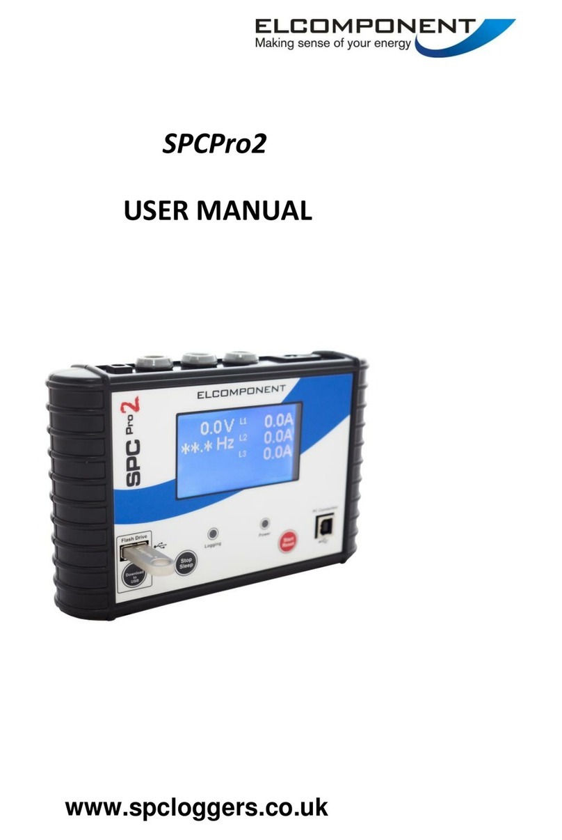
Foryou TPMAI1DIC1 User manual

TPMS USER MANUALTPMS USER MANUAL


Caution:
NOTE:
Changes or modifications not expressly approved by the party
responsible for compliance could void the user's authority to
operate the equipment.
This device complies with part 15 of the FCC Rules. Operation is
subject to the following two conditions: (1) this device may not
cause harmful interference, and (2) this device must accept any
interference received, including interference that may cause
undesired operation

Thank you for choosing products. Please carefully read
the manual, you will learn to use all the functions of the new tire pressure
monitoring system
*
TPMAI1DIC1
USER MANUAL
This product is applicable to passenger cars
*

Contents
Precautions
Contents
Product description
Installation
Troubleshooting
Operation
Equipment connection
1
2
3
Transmitter installation steps
4
Receiver installation steps
5
System introduction
6
System settings
Backlight settings 7
14
16
18
17
Disclaimer
Common alerting mode

Precautions
Before using this product, please be sure to have read the <User Manual>
Precautions
This product is applicable to 12V cathode
grounding battery system car, please do not install
the product in 24V truck or bus.
Do not install the product in the field of impacting
driver's vision or driving operation.
In order to avoid traffic accidents caused by
decentralizing driver's attention, please do not
operate the product while driving. If there is
operation need, please park your car in a safe
place.
Do not expose the product in the over-moist
environment or let it touch water, otherwise they will
lead to electrical short circuit damage
Avoid the strong impact on the product,otherwise it
will damage the structure components of the
product.
Do not open the product crust or adjust any other
parts oneself.If there is a service need ,please go
to a professional repair service center for
consultation.
1
1
3
4
5
6
12V
24V
2
This product provides one-year free warranty, If there is quality
problem,please contact with local dealers. Man-made factors
such as incorrect installation, improper use,contacting with
harmful substances damage are not in the warranty list, please
keep your warranty card and certificate well for servicing.

2
Product Description
1
2
3
1
4
1
-40 ~ 105℃℃
≤95%RH
73×67×20mm
Normal use>6 years
0kPa~800kPa
-30 ~ 70℃℃
433.92MHz
130×40×45mm
DC 12 4V
433 92MHz.
Product Description
Composing component
Tire Pressure Monitoring System includes the following components:
SN. Name Icon Amount
Receiver
Transimitter
Paste board
Product technical specifications
Operating humidity
Product Size
Product life
Pressure measuring range
Receive frequency
Transimitter frequency
Operating temperature
Receiver
Operating temperature
Operating hvoltage
Product Size
Transimitter

Installation
3
Installatio
1
2
3
4
jacket nut
sensor
protective cap
flat washer
rubber washer
5
6
Transmitter installation steps:
remove tires from the car, remove the rubber tire after the tires
were deflated
clean the rim
Screw the protective cap, jacket nut, flat washer from the
transmitter to be installed.
Insert sensor into the corresponding location of the tire valve,
and then be fixed by jacket nut.
Pay attention to avoid the location of transmitters when install
rubber tire. After inflation of the tires according to the tire
inflation pressure value , screw protective cap to complete the
installation.
In accordance with the above steps to install other transmitters.
[ ] Transmitter should be installed by professionals. The steps must be in
accordance with Stickers shown on the transmitter to ensure that the
installation is correct and reliable.
:Note ①
②As the transmitters install on the valve mouth, extrusion on the rubber
valve should be avoid to prevent leakage or damage.
③After transmitter installation, you must do the tire dynamic balance test,
otherwise normal driving will be affected.The product only applies to
vacuum tire installation.

4
Installation
Receiver installation steps:
1
2
3
TM
OK
L
Take out receiver, receiver paste board from the box.
Tear up the adhesive protective film on paste board, stick the
receiver on the selected position, adjust the position of the
receiver in order to help the driver read the display information
on the LCD screen.
Connect the power anode with ACC ignition wiring, cathode
with the vehicle power ground. To ensure that the power
connection is correct and the input power is 12 ± 4V DC power.
The installation is completed.

5
Operation
Operation
Pressure Units:kPa
Pressure Units:psi
Pressure Units:bar
Celsius Temperature units:
Fahrenheit Temperature units:
Pressure Alerting
TemperatureAlerting
User Settings
Tire ID read
Tire exchange
Transmitter battery
℃
Tire (Tyre) key
Backlight (Light) key
Menu key
Ok key
Pressure alerting light
Temperature alerting light
System Introduction
After the receiver power wiring is connected, the vehicle ignition
switch turns on, the system start self-checking. LCD screen light up
all the display information ,at the same time buzzer starts buzzing.

6
Operation
[]:The system will displays the data it stored last time when turning
on the ignition switch after the automobile being parked a period of time,
and will refresh in one minute when the speed of the vehicle arrive 20 km/h.
Note
After self-checking passed, the system enter into tire checking
status display, (below) normal work interface, if the self-checking
does not pass, buzzer start buzzing and LED light lights up.

7
Operation
()Tire information display setting
Press key to select function display mode
Press key to enter into information display setting
mode,show / ,and the interface continue flashing,
indicating that the new settings can be carried out.Press
key,select (tire general display)or (tire circle display).
。
:
:
Press key to save settings or press key not to
save the settings, and return to the current display
mode
(circle display) System cycle shows information
of each tire
(General display) Display the minimum
pressure data value of the tire. Press key can
read other tire information one by one.
1
3
2
System Settings
In normal working mode,press key for 3 seconds to enter into
the menu settings interface,press key can switch between ~
and then press key can enter into corresponding function
settingmode or press for 3 seconds to exit from the interface:

()Units display settings
Press key to enter into unit display setting
mode,press key to select pressure unit / / .
Press key to select function display mode
8
Operation
Press key to complete the pressure unit setting,and enter
into temperature unit setting.
Press key to select temperature unit /
Press Key To Save Settings Or Press Key Not
To Save The Settings, And Return To The Current
Display Mode .
1
2
3
4
5

9
Operation
After selected ,press key to display factory default
high-pressure limit, and then press key to display the
factory default low-pressure limit, press key again to
display the factory default high temperature limit, and finally
press key to save settings or press key not to save
the settings, and return to the current display mode .
(Pressure and temperature limits setting)
Press key to select function display mode .
Press key to enter into pressure, temperature alerting
limit setting mode, press key to select / (the
factory default settings / user-settings).
1
2
3

After select ,press key to operate self-setting limit
(defaulting select the first number of high-pressure limit), press
key to select setting position, the selected position will keep
flashing until the next position is selected by pressing key.
Press key to adjust the size of flashing bit values until the
last high-temperature limit is set up,.Press key to save
settings or press key not to save the settings, and return to
the current display mode
。
10
Operation
4

11
Operation
(Tire ID exchange setting)
Press key to select function display mode
Press key to enter into the tire ID exchange mode,
press key to select the tire, selected tires keep in
flashing state.
2
3Press key, the No. on corresponding location of selected
tire starts flashing, press key to adjust( ~ ) to the No.
which in corresponding location of tire with the needs of
exchange.
4Press key to save Settings or press key not to save
the settings, and return to the the nd step of current display
mode, press key to return to the current display mode
.
2

12
Operation
Press key to enter into the tire ID No. read mode, press
key to select the tire, selected tires keep in flashing state.
(Tire ID No. read setting)
Before system work properly, the tires ID No. need to be read,
then the transmitter can send data to the receiver real-time.
Press key to select function display mode
Press key to save Settings or press key not to save
the settings, and return to the the nd step of current display
mode, press key to return to the current display mode
2
1
2
4
Press key, the No. on corresponding location of selected
tire start flashing, waiting to receive the ID signal. At this time
deflate the selected tire( reference the following [ ])After
received the ID signal, the buzzer start buzzing and the
digital flashing frequency speed up.
Note
3

13
Operation
(Spare tire activation settings)
Press keys to choose function display mode .
Press key to enter into spare tire setup mode ,display
/ , and continue to winkle, indicating that the new settings
can be carried out. Press key to select or
1
2
Press key to save Settings or press key not to save
the settings, and return to the current display mode
3
Receiver in working status,press key to turn on the backlight,
press key again, turn off the backlight
Backlight settings
[ ] ID No. studying has been completed before leave factory, please follow the transmitter
stickers to install. Tire ID No. studying, relative atmospheric pressure is / = to 60kPa, the
deflation is 30kPa in 1 minute.
>
Note
Finish learning of other tires according above steps

14
Operation
Common Alerting Mode
Fast leaking alerting, buzzer buzzing, pressure warning light
flashing.
High temperature alerting, buzzer buzzing, pressure warning
light flashing.
High pressure alerting, buzzer buzzing, pressure warning light
flashing.
Low pressure alerting, buzzer buzzing, pressure warning light
flashing.

Alerting default limits
High temperature alerting ≥℃80
Low pressure alerting ≤190kPa
High pressure alerting ≥330kPa
15
Transmitter failure alerting, buzzer buzzing
Low voltage alerting, buzzer buzzing
No signal alerting, buzzer buzzing
Operation
*
[Notice] If the alerting state displays, please solve the problem in time, which could save transmitter
power consumption.
In alerting state, press any button to stop alerting sound.
①
②
Table of contents
