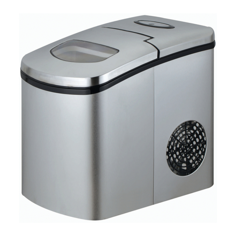
Foster FS Series User manual

By Appointment to
Her Majesty Queen Elizabeth II
Suppliers of Commercial Refrigeraon
Foster Refrigerator, King’s Lynn
ISO 9001 ISO 14001
FS Cubers
Original Installation & Operation Instructions
Foster Refrigerator
Oldmedow Road
King’s Lynn
Norfolk, PE30 4JU
United Kingdom
A division of ITW Ltd
English
Call: +44 (0)843 216 8800 Fax: +44 (0)843 216 4700
www.fosterrefrigerator.co.uk
Email:support@foster-uk.com

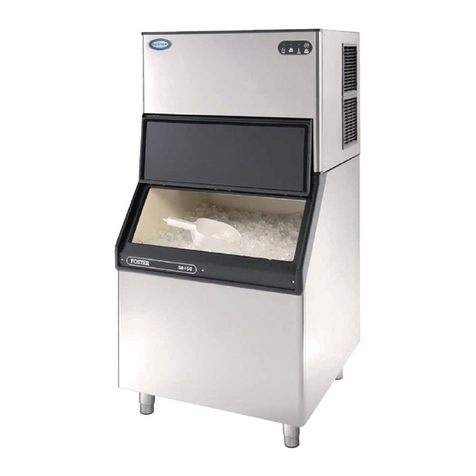
Models applicable to this manual
English
FS20
FS40
FS50
FS90
Important Note to the Installer:
Please ensure that this document is passed to the user as it
contains important guidelines on operaon, loading, cleaning and
general maintenance and should be kept for reference.
Climate class
Climate class indicated on the serial plate, shows the temperature & humidity at which this appliance has
been tested, for the purposes of establishing values in line with European standards.
Electrical safety
Foster Refrigerator recommends that the equipment is electrically connected via a Residual Current Device;
such as a Residual Current Circuit Breaker (RCCB) type socket, or through a Residual Current Circuit Breaker
with Overload Protecon (RCBO) supplied circuit.
Should it be necessary to replace the fuse. The replacement fuse must be of the value stated on the serial
label for the cabinet.
Warnings
This manual provides all necessary informaon for the correct installaon, use and maintenance of the
machine. The user must read the manual carefully and always refer to it for the use of the machine.It
should be kept in a safe place, and be accessible to all authorised operators (installer, user, maintainer).
All safety informaon must be adherred to.
• The equipment contains greenhouse eect uoride gas governed by the Kyoto protocol, in quanes
indicated on the registraon plate. The type of refrigerant gas present in the refrigeraon circuit of the
equipment is detailed on the registraon plate (on page 10). The GWP (Global Warming Potenal) of
the HFC R134a gas is 1430, HFC R404A is 3922.
• The system is hermecally sealed.
• The equivalent CO2 data is displayed on the registraon plate (On page 10 of the manual)
• According to Regulaon (EC) 1272/2008, gases R134a and R404A are non-ammable and non toxic gas-
es. In dierent concentraons, they may be asphyxiang. Contact with the liquid can cause burns and
freezing.
• The gas in the system is under pressure and may explode if heated.
1

General safety
Do not store explosive substances such as aerosol cans with a ammable propellant in this appliance.
Keep all venlaon openings in the appliance or in the structure of a built in unit clear of any obstrucons.
The appliance is air ght when the door is closed therefore under no circumstances should any living body
be stored or ‘locked in’ the applicance.
The moving of the appliance should be carried out by competent personnel, ensure that two or more people
are used to guide and support the appliance, the appliance should not be moved over uneven surfaces.
The emied sound level for these appliance are:-
FS20 is 57db(A)
FS40 is 58db(A)
FS50 is 59db(A)
FS90 is 62db(A)
To ensure stability the appliance should be located on a at, level surface, correctly loaded with the castors
locked.
If the supply cord is damaged, it must be replaced by the manufacturer, it’s service agent or similarly
qualied persons in order to avoid hazards.
Care should be taken to avoid prolonged contact with cold surfaces with unprotected body parts,
Correct PPE to be used at all me.
English
2
• This appliance is intended to be used in household and
commercial applicaons.
• Connect only to the drinking water supply.
• Use the new water pipe supplied with the machine. We
recommend that any water pipes used previously are
not re-used
Do not start the appliance prior to the installer conrming
that the installaon is complete.

English
8
Connecon to the water supply and drain
Install the water connecon before the electrical connecons.
Connect the 3/4” supply pipe (supplied) to the machine and to the cold
water supply.
For praccal and safety purposes, it is advisable to install a shut-o valve (not
supplied) (g 1: 1.Switch; 2.Socket; 3.Electrical Plug; 4.Water
Supply (one per unit); 5.Valve; 6. Water drain from the container: 7.Water
drain with open siphon.). Apply the exibile pipe (supplied)with a 20mm
inner diameter and of adequate length (not more than 1 metre from the
machine) to the water drain ng of the machine.
3
Install the machine so that the venlaon of the cooling unit is not
obstructed in any way.
Avoid installaon in a dusty enviroment, this can block the cooling condenser
and prevent the machine from operang.
To prevent the ice from becoming contaminated , never store food, boles,
etc in the container.
Do not leave the ice container open, unless retrieving ice.
6
7
Min 10˚C (50˚F)
Max 32˚C ( 90˚F)
H
2
O
Max 0,5 M Pa
(5bar)
Min 0,1 MP a (1bar)
Locang the appliance
1

Inial start up
Prior to using the machince.
1. Ensure that the machine has not been damaged during transport
2. Remove any items from the ice bin
3. Clean inside the container with a damp sponge with warm water
and a lile sodium bicarbonate; rinse with clean water and dry carefully
English
Before starng the machine ensure the following is carried out before starng
the unit.
Note: A minimum fall of 3% is needed to ensure adequete water ow
from the machine. Care should be taken to ensure the drain
pipes are not restricted in any way.
8
Connecng the power supply.
If the power supply cable is damaged, it must be replaced by qualied personnel to prevent any hazards to
persons.
Connect the machine to a suitable power supply.
When connecng the machine, ensure hands are dry and the socket is switched o
Connect the machine to the power supply only aer having veried that the mains voltage
corresponds to that on the serial number plate on the rear panel of the appliance.
(On page 10 of the manual)
The maximum voltage variaon tolerance allowed is ± 10% of the rated value.
It is recommended that the machine is installed with its own isolator switch as all pole contact separaon.
All cables and isolators must be sized according to the rang indicated on the serial number plate.
(On page 10 of the manual)
The socket must be easily accessible.
4
6
7

English
Warning: When switching on for the rst me or aer a prolonged period without use or aer
cleaning, the tray in the evaporator area must be lled with water (Fig. 2). In order to carry out this
operaon , li the door , slide back the curtainand pour clean water into the evaporator tray.
For subsequent cycles this will not be necessart.
Check the connecons to mains water and electricity, open the water supply tap. To start the machine,
press the illuminated switch (Fig. 3). It is recommended to not use the rst ve cycles of ice.
The ice maker is equipped with a thermostat inside the ice cabinet (Fig. 4), which stops the
machine and the producon of ice when the sensor comes into contact with the ice accumulated
inside the cabinet. Never switch o the water supply when the machine is on, do not obstruct the
air intake ducts.
Note: Aer removing ice, free the control bulb from any ice residue to ensure that ice making restarts
swily (Fig. 4).
5
234
Ice Weigth
Cube adjustment
Cube dimensions can vary depending on varying condions.
To adjust the size of the cube, rotate the adjustement screw (g.5)
clockwise to increase the sizeant an-clockwise to decrease the size.
5

English
Cleaning and maintenance
Disconnect the electrical power supply from the appliance to perform maintenance and
cleaning operaons
Use a cloth dampened with a specic chlorine-free product for stainless steel to clean the case.
Cleaning the air condenser.
To maximise the eciency and life of you machine, the condenser at the front of the machine must cleaned
periodically (Fig 6)
Do not use wire brushes or blunt objects to clean the condensor, use a so brush or vacuum with a suitable
nozzle. Where a condenser requires cleaning with a cleaner other than a brush or vaccum. This should be
out by competent engineer.
Cleaning the water inlet lter
It is recommended that this is carried out by a competent engineer.
Close the water shut-o valve, disconnect the water inlet pipe and remove the lter valve with a pair of
pliers.
Clean the lter with a water jet and then reassemble it.
6
Malfuncon
In the event of a Fault, it is recommended to disconnect the electrical and water supply
1. Check that the water supply tap is on.
2. Check that power, that the plug is correctly inserted, and that it is switched on and the fuse has not
failed
3. Check that there are no abormal vibraons.
4. If there is a water leak, stop the machine rst before making any adjustments.
5. If ice producon is low, check that the condenser is clean, check for the build up of limescale
accumulaon of the sprayer nozzles.
6. To Check that the cabinet sensor is working: rest an ice cube on the bulb inside the container. This
should stop ice producon within 1 minute, when the cube is removed. Ice producon should
restart within 1 minute.
7. Between summer and winter the cabinet thermometer may vary the maximum quanty of ice in
the cabinet, in order to adjust this value, contact an authorised installer.
6

English
Cleaning the ice bin
Remove the ice from the ice bin. Clean inside the bin with a sponge dampened with warm water and a lile
sodium bicarbonate.
Rinse with clean water and dry carefully.
Cleaning and Sanicaon
The “Self Cleaning” funcon should be used regualary to remove the limescale build up.
Cleaning should be carried out three to four mes a year, howeverin areas of very hardwater more fre-
quent cleaning maybe necessary
Cleaning kit (oponal)
The kit is composed of one confecon of
acid citric (1 kg), and instrucons for the
cleaning procedure.
Part Number 16251859
Quantes of citric acid to be mixed with water in the bole to obtain the mix-
ture
MODEL CITRIC ACID QTY
20-25 Kg 200g
30-40 Kg 250g
50 Kg 350g
70-90 Kg 500g
7

English
• Turn the machine o.
• Remove all ice from the container
• Prepare the soluon by dissolving the citric acid in warm water (max 40°C), according to the quanies
shown on the Previous table.
• Posion the internal switch in the cleaning posion (g 7).
• Pour the cleaning product into the evaporator tray (g 8)
• Turn the power to the machine on and wait for at least 2 hours.
• Aer two hours, switch the machine o and drain the soluon in the evaporator tray into the cabinet
(Fig 9)
• Replace the cap and pour clean water into the tray to ll it to capacity, and start the machine again.
• Repeat the operaon at least 5 mes to eliminate the presence of citric acid and saniser.
• Aer this me has elapsed, switch the machine o and remove the cap to discharge the water in the
evaporator tray, then replace cap.
• Finally, return the switch to ice mode.
• Aer the cleaning funcon, rinse the cabinet well.
• If the machine remains unused for long periods: Switch the machine o;
Remove all ice from the container;
Discharge all water;
Clean carefully;
Leave the container door ajar.
CLEAN
8
789
Starting the wash & sanitation Cycle
When handling citric acid and citric acid soluon

Before calling your supplier or enginner please make sure that:
a. The plug is located in the socket and the mains power supply is on i.e. is the controller illuminated?.
b. Check to see if the unit is in standby.
c. The fuse for the cabinet has not failed.
d. The cabinet is posioned correctly – as detailed in the rear of this manual
e. The condenser is not blocked or dirty
f. Defrost is not in progress or required
If the reason for the malfuncon cannot be idened, disconnect the electrical supply to the unit and
contact your supplier. When requesng a service call, please quote the model and serial number which can
be found on the white label located on the back of the unit (Serial Number starts CMA......).
English
9

English
CODE
MODEL
S/N
CM96908583/0
CMA1001500
380-415V/3 50Hz1 3,0A 247W
220-240V 60Hz 1,0A 123W
R134a2 ,000 Kg
ST IP22CLASSI P
GAS
1,00 Kg / dm3CO2 Equiv.
V1
V2
CODE S/N
99999 W 99999 W 99999 W
YEAR: 2015
Manuale di Istruzione/Instruction Manual/Notice d’instructions/Bedienungsanleitungen
IT
Serie CS / CS Series
CS 20 / CS 25 / CS30 / CS 40 / CS 50 / CS 70 / CS 90
CODE
MODEL
S/N
CM96908583/0
CMA1001500
380-415V/3 50Hz 13,0A 247W
220-240V 60Hz1 ,0A 123W
R134a2 ,000 Kg
ST IP22CLASSI P
GAS
1,00 Kg / dm3CO2 Equiv.
V1
V2
CODE S/N
99999 W 99999 W 99999 W
YEAR: 2015
CODE
MODEL
S/N
CM96908583/0
CMA1001500
380-415V/3 50Hz 13,0A 247W
220-240V 60Hz1 ,0A1 23W
R134a2 ,000 Kg
ST IP22CLASSI P
GAS
1,00 Kg / dm3CO2 Equiv.
V1
V2
CODE S/N
99999 W 99999 W 99999 W
YEAR: 2015
CODE
MODEL
S/N
CM96908583/0
CMA1001500
380-415V/3 50Hz 13,0A 247W
220-240V 60Hz1 ,0A 123W
R134a 2,000 Kg
ST IP22CLASS IP
GAS
1,00 Kg / dm3CO2 Equiv.
V1
V2
CODE S/N
99999 W 99999 W 99999 W
YEAR: 2015
10

UK Head Oce
Foster Refrigerator
Oldmedow Road
Kings Lynn
Norfolk
PE30 4JU
a Division of ITW (UK) Ltd
Tel: +44 (0)843 216 8833
Fax: +44 (0)843 216 4707
Email: support@foster-uk.com
Website: www.fosterrefrigerator.co.uk
This manual suits for next models
4
Table of contents
Other Foster Ice Maker manuals
