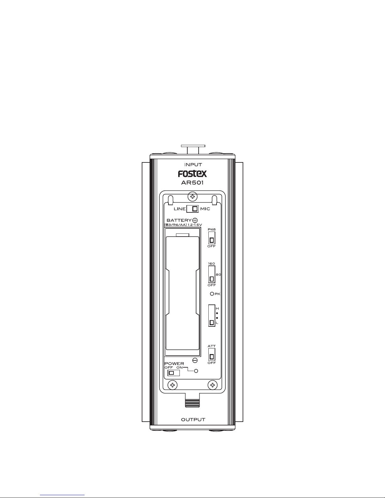
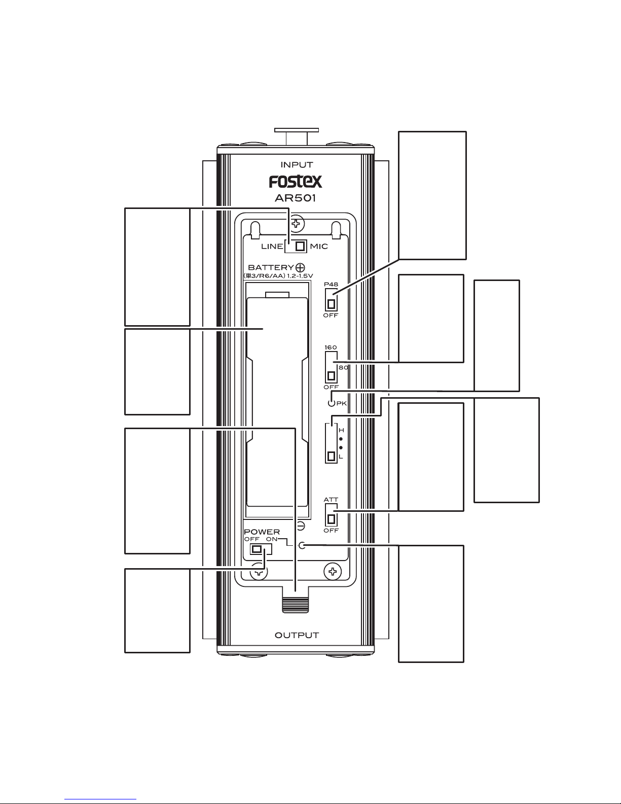
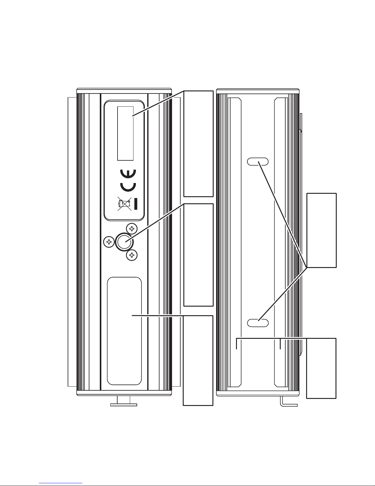
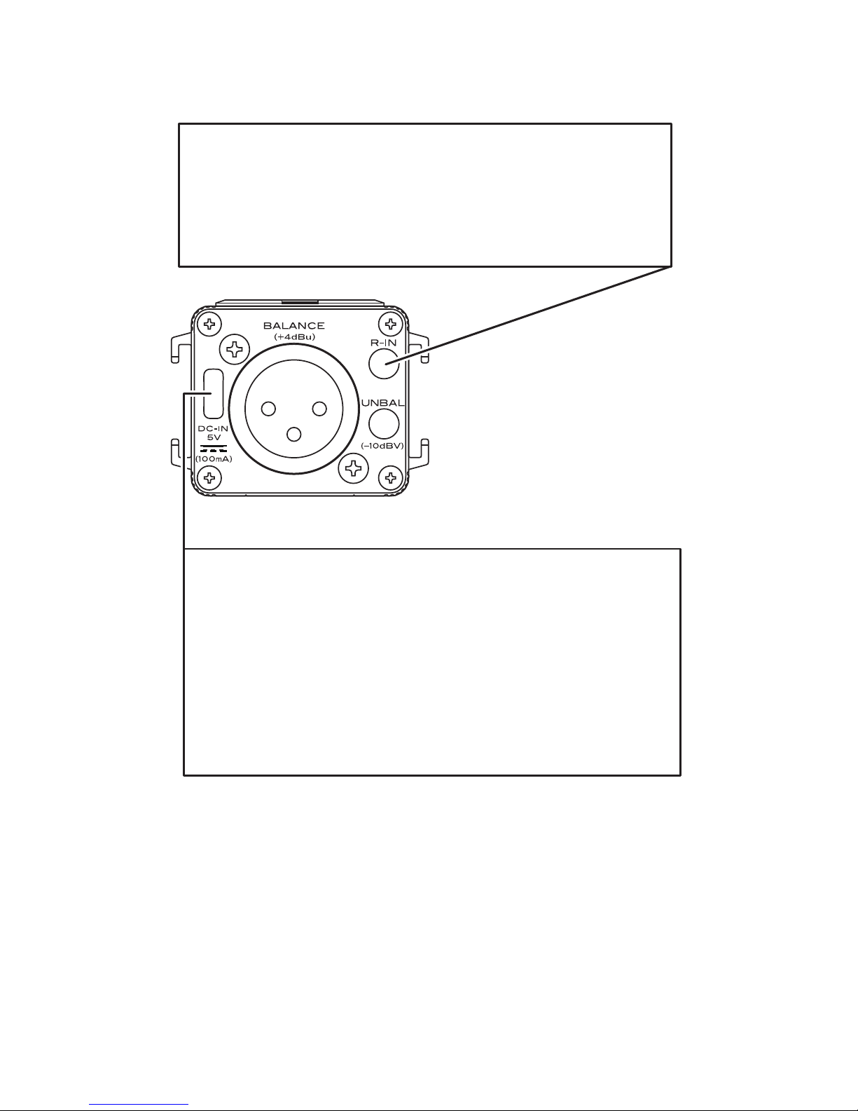
Fostex AR501 User manual

AR501 MIC PREAMPLIFIER
Owner's Manual

2
Table of contents
3
6
9
15
17
19
21
22
24
25
27
1.
2.
3.
4.
5.
6.
7.
8.
9.
10.
11.
Names and functions . . . . . . . . . . . . . . . . . . .
Input and Output . . . . . . . . . . . . . . . . . . . . . .
Switches and LED's inside Battery Cover . .
Power supply . . . . . . . . . . . . . . . . . . . . . . . . .
Chassis . . . . . . . . . . . . . . . . . . . . . . . . . . . . . .
Accessories . . . . . . . . . . . . . . . . . . . . . . . . . .
Typical connections . . . . . . . . . . . . . . . . . . . .
Input and Output specications . . . . . . . . . . .
Performances . . . . . . . . . . . . . . . . . . . . . . . . .
Dimensions and weight . . . . . . . . . . . . . . . . .
Block Diagram . . . . . . . . . . . . . . . . . . . . . . . .

3
1. Names and functions
< Input Panel >
< Output Panel >
INPUT
Balancedinput
XLR-3P(Female)
BALANCEDOUT
Balancedoutput
XLR-3P(Male)
DC-IN
DCpowerinlet
microUSB
UNBALOUT
Unbalancedoutput
Stereominijack
R-IN
Audiosignalinput
forRight
Stereominijack

4
< Top Panel >
BATTERYCOVER
Coverforbattery
andswitches
Transparentplastic
INPUTSEL
Inputselectorswitch
LINE/MIC
PHANTOMPOWER
Powersupply
formicrophone
OFF/P48
PEAKINDICATOR
Red
HPF
Highpassfilter
80/160(Hz)
GAIN
Gainselectswitch
L/•/•/H
POWER
INDICATOR
PowerindicatorLED
Red/Green/Yellow
ATTENUATOR
Attenuatorswitch
OFF/ATT
POWER
Powerswitch
OFF/ON
BATTERY
Battery
compartment
R6,AAbattery

5
< Bottom & Side Panel >
SHOERAIL
USERLABELAREA
Areatoattachuserlabel
TRIPODSOCKETHOLE
Screwholefortripod
1/4”
SERIALLABEL
Labelforserialnumber
JOINTSTOPPER
Grooveforfixingjoint

6
2. Input and Output
< Input >
INPUTSEL
MIC
LINE
Nominal
-60/-45/-30/-20dBu
+4dBu
Max
-40/-25/-10/0dBu
+24dBu
INPUTConnector
Connectheretheoutputfrommicrophoneorlinelevelequipment.
UseINPUTSELswitchaccordingtothetypeofdeviceconnected.
(Referto3.SwitchesandLED’ sinsideBatteryCover.)
[Connector]:XLR(Female)/Pin:3pins(PinNo.2asHOT)
[Inputimpedance]
LINE: 10kΩ or higher
MIC: 2kΩ or higher
[Inputlevel]

7
< Output >
ATT
OFF
ON
Nominal
-10dBV
-50dBV
MAX
+10dBV
-30dBV
BALANCEDOUTConnector
Outputthelinelevelaudiosignalinbalancedconfiguration.
[Connector]:XLR(Male)/Pins:3pins/No.2asHOT
[Nominaloutputlevel]:+4dBu
[Max.outputlevel]:+24dBu
[Applicable load impedance]: 10kΩ or more
UNBALANCEDOUTConnector
Outputtheaudiosignalinunbalancedconfiguration.(The
samesignalwillappearonbothLandRchannels.)
YoucanreducetheoutputlevelbyusingATTswitch.
((Referto3.SwitchesandLED’ sinsideBatteryCover)).
[Connector]:Stereominijack/ø3.5mm
[Nominaloutputlevel]:-10dBV
[Max.outputlevel]:+10dBV

8
< Misc. >
R-INconnector
Connectingalinelevelaudiosignalherewillresultanoutput
viaUNBALANCEDOUTconnectorRightchannel.
ItisusefulwhenconnectinganotherAR501toperformin
stereo.
[Connector]:Stereominijack/ø3.5mm
DC-INconnector
Usetoconnectanexternalpowersource.
RecommendedDCvoltageis5V.
Anordinarymobilebatterypackcanbeused.
[Connector]:microUSB
[Inputvoltage]:5V±3%
[Currentconsumption]:100mApeak.
Note:Whenicomingvoltagegoesbelowtheabovespec.orif
itcutsout,AR501willautomaticallyswitchthepowersource
tointernalbattery.

9
3. Switches and LED's inside Battery Cover
MIC
LINE
OFF
P48
INPUTSELSwitch
UseINPUTSELswitchaccordingtothetypeofequipment
connected.
Fordynamicorcondensertypemicrophone
Forlinelevelequipmentsuchasanaudiomixer.
*WhenchoosingLINE,nosignalbecomesavailableon
BALANCEDOUTconnector.
PHANTOMPOWERSwitch
Powersupplyforcondensermicrophone
INPUTSELSwitch
UseINPUTSELswitchaccordingtothetypeofequipment
connected.
Novoltagesupplied.
48VvoltageissuppliedtoINPUTconnector.24V
willbesuppliedatpowersavingmode.

10
H
・
・
LINE
80
160
Reducingthefrequencyrangeof80Hzand
below.
Reducingthefrequencyrangeof160Hzand
below.
HPF(HighPassFilter)Switch
Usedtoreducelowfrequencynoisesuchaswindblowon
themicrophoneorhumnoisegeneratedbyACpowerfacility.
*Attenuation:-6dB/oct.
GAINSwitchandPEAKIndicator
Usedtoadjustthemicrophoneampgainaccordingtothe
microphonesensitivity.SettheGAINswitchappropriately
referringtothePK(PEAKindicator)LEDandtheinputlevelof
equipmentconnectedtoOUTPUT.
MICSensitivity(dBu)
-60
-45
-30
-20
GAIN(dB)
+64
+49
+34
+24
*WhentheGAINisadjustedproperlyacccordingtothechart
above,thenominallevelwillappearviaOUTPUTconnector.

11
OFF
ON
Noattenuation(nominaloutputlevel:-10dBV)
Attenationapplied(nominaloutputlevel:-50dBV)
OUTPUTATTSwitch
UsedtoattenuatethesignallevelatUNBALANCEDOUT.
SettoONwhenconnectingtolowinputequipmentsuchas
micinofDSLRcamera.
BatteryCompartment
InsertapieceofAAbattery.
Typeofbattery:Ni-MH(Nickel
MetalHydride),Alkaline
POWERSwitch
Mainpowerswitch
ofAR501
POWERINDICATOR
PowerindicatorLED.
(Fordetail,refertonextpage.)

12
< POWER Indicator >
Lit when power turns ON. LED condition differs depending on the
function mode.
[Internal battery]: Right after powering on
Lightingpattern
Normalmode/Preparingtosettingup
Powersavingmode/Preparingtosettingup
Setupcompleted
(1sec.)x3times
(1sec.)x3times Flashinggreentwicerapidly
for3sec.period
G Green
R Red
Flashinggreenonceslowly
for3sec.period
G Green
Flashingred3timesrapidly
If you operate the PHANTOM POWER switch from OFF to ON to OFF
during the setting up period, AR501 will enter Power saving mode.
It will reduce the internal circuitry working voltage and cut down the
power consumption by approx. 40%. (The supply voltage at P48 is
going to be 24V during the power saving mode.)
The power saving mode will be memorized internally.
In order to cancel the mode, turn the power OFF once, then repeat
the same MIC POWER switch operation again.
During operation, the indicator will perform as following.

13
* Replace the battery when Red LED becomes ashing.
* Replace the battery immediately when Red LED is lit solid as the
power is forced to OFF on both internal circuitry as well as P48.
[Internal battery]: During normal mode operation
•••
•••
•••
•••
•••
Lightingpattern P48 BATT.
amount
Flashing:
GGreen2times
Flashing:
YYellow2times
Flashing:
GGreen2times
Red1time
Flashing:
Y Yellow2times
R Red1time
R Red
Litsolid
OFF
ON
OFF
ON
Forcedto
OFF
High
Low
High
Low
Runout

14
[Internal battery]: During power saving mode operation
•••
•••
•••
•••
•••
Lightingpattern P48 BATT.
amount
Flashing:
GGreen
Flashing:
YYellow
Flashing:
GGreen1time
Red1time
Flashing:
YYellow1time
RRed1time
R Red
Litsolid
OFF
ON
OFF
ON
Forcedto
OFF
High
Low
High
Low
Runout
* The supply voltage at P48 is 24V during the power saving mode.
* Replace the battery when Red LED becomes ashing.
* Replace the battery immediately when Red LED is lit solid as the
power is forced to OFF on both internal circuitry as well as P48.
[DC IN]: During operation
•••
••• Litsolid:
G Green
Litsolid:
Y Yellow
OFF
ON
Lightingpattern P48
* During DC-IN operation, no preparation to the setting up will not be
executed.
* During DC-IN operation, the battery amount is not detected.

15
4. Power
< Internal Battery >
AR501 uses a piece of AA battery.
The sutied type of battery is N-MH rechargeable battery or Alkaline
battery.
* AR501 does not have battery charging function.
Operating time reference value.
NormalMode Powersavingmode
P48(Powertomic)
BatteryType
OFFOFF ON ON
P48(Powertomic)
AlkalineBatt.
(LR6)
Ni-MH
(eneloop)
Ni-MH
(enelooppro)
Approx.
9hours
Approx.
10hours
Approx.
12hours
Approx.
3hours
Approx.
4hours
Approx.
5hours
Approx.
15hours
Approx.
16hours
Approx.
18hours
Approx.
8hours
Approx.
9hours
Approx.
11hours
Caution
* The above chart is only a reference. It does not guarantee the actu-
al operating time. The operating time differs depending on the using
condition and environmental variations.
* Ni-MH battery gradually reduce its max. capacity by repeating the
cycle of discharge.
* For the measurement of the above chart, we have used brand new
Ni-MH battery once discharged and then fully charged.

16
Memo
* As spontaneous self-discharge occurs on Ni-MH battery, we rec-
ommend using it immediately after charging or charge it rigt before
using. Alternatively, we recommend the next generation rechargeable
battery that has improved self-discharge characteristic such as "en-
eloop".
* As Alkaline battery drastically reduces its discharge characteristic
under low temperature, we recommend Ni-MH battery under such
circumstances.
* eneloop is a registered trade name.
< External Power >
Memo
* When powered by an external power source, AR501 does not con-
sume the power from internal battery.
* The power indicator becomes lit (use of internal battery makes the
indicator ashing.).
* If the external power cuts out with some reason, it will automatically
switch the power source to the internal battery. It is possible to use
the external power as main source and internal battery as backup
source.
DC-INConnector
AR501canbepoweredbyconnectinganexternalpower
sourcetoDC-INsuchasmobilebatterypack.

17
5. Chassis
< Screw hole for tripod >
< Shoe rail >
AR501provides1/4”threadonthebottomchassis
sothatyoucanattachittoastandardtripodand
cameragear.
Byinsertingthejointplatecomesinthepackage
here,multiplenumberofAR501canbejointed.
Pleasereferto<Joint>onthesection6.
Accessoriesformoredetails.

18
< Attaching user label >
AR501hasapitonthebottomchassistostickauserlabelfor
theusers’convenience.Useitforattachingalabelintheway
youlikesuchascompanyIDandadministrativecontrolnumber
plate.Sincethepitisretracted,itavoidsthelabelgetting
damagedwhenattachingatripod.
Recommendedlabeldimensions:41x13mm,CornerR2.5mm

19
6. Accessories
< Joint (coupling plate) >
Used to joint multiple numbers of AR501.
Make the shoe rail of every unit facing each other and insert the joint
in between.
Fit the joint to one unit rst and then attach the other later.
Other purpose of joint is; xing the joint to somewhere like a wall us-
ing 3 mm in diameter screw holes, then attach the AR501 to the joint.
Recommended screw: 3 mm in diameter, more than 10 mm in length,
counter-sunk type screw (other type cannot be used).
* Before fixing the joint, ensure the fixing area has enough
strength to hold the AR501.
WALL

20
84mm
< Reference dimensions >
< Cable >
Used to connect AR501 unbalanced output to other equipment
such as a DSLR camera and audio recorder and also to connect 2 x
AR501's in cascade.
For the convenience of handling, a curl cord is used.
[Connectors]: stereo min plug ø 3.5 mm.
[Length]: 20 cm when shrunk, 40 cm when fully expanded.
Table of contents
Other Fostex Amplifier manuals

Fostex
Fostex HP-A4BL User manual

Fostex
Fostex HP-A8C User manual

Fostex
Fostex AP3060 User manual

Fostex
Fostex HP-A4BL Use and care manual

Fostex
Fostex HP-A8MK2 User manual

Fostex
Fostex AP1020 User manual

Fostex
Fostex AP05 User manual

Fostex
Fostex HP-V1 User manual

Fostex
Fostex PH-5 User manual

Fostex
Fostex 5030 Instruction Manual

Fostex
Fostex HP-P1 User manual

Fostex
Fostex PH-50 User manual

Fostex
Fostex HP-A4 User manual

Fostex
Fostex 300 Troubleshooting guide

Fostex
Fostex HP-A8 User manual

Fostex
Fostex 5030 User manual

Fostex
Fostex PH-100 User manual

Fostex
Fostex 5030 User manual

Fostex
Fostex HP-V8 User manual

Fostex
Fostex PH-100 User manual