Fostex NF-1 Quick reference guide

Technical White Paper
NEAR FIELD STUDIO MONITOR

- 2 -

- 3 -
♦Employment of a 16 cm woofer featuring a
newly developed HP diaphragm has made it a
reality to reproduce low distortion and highly
transient sound which used to be only a dream
with conventional diaphragms.
♦Anti-resonance of diaphragm edges has been
successfully eliminated. The newly developed
UDR tangential diaphragm edge and push-pull
damper used in the woofer provide a breakthrough
in linearity and responsiveness to subtle signals.
♦Highly rigid die-cast aluminum frames
engineered to eliminate sound colorization often
occurring due to undesirable natural resonances
are used on the woofer and tweeter.
♦Tweeters, comprising a newly developed UFLC
diaphragm (soft dome) offering excellent response
and reproduction performance, are capable of
handling a wide frequency coverage of up to 40
kHz.
♦The network used is of an exceptionally low
loss 6 dB crossover design which ensures
extremely natural transition between the woofer
and tweeter.
♦The time-aligned enclosure has a baffle shaped
to keep it free of natural resonances caused by
diffracted reflection sounds.
♦The use of an HP diaphragm and dome tweeter
has widened the listening area, which was not
possible with previous technology.
♦An ideal internal processing method of natural
resonances developed by reflected sounds within
enclosures is now an actuality by removing such
natural resonances by an HP sound reflector.
♦Terminals for bi-amplification systems are
provided for convenience in meeting studio-
specific environmental requirements.
♦Employment of minimal magnetic leakage
design on both woofers and tweeters makes
placement of the system in close proximity to
monitors viable.
FEATURES
THE "SHOULD BE" OF MONITOR
Before undertaking development of NF-1, we recognized
anew the following 5 points as mandatory requirements
near-field monitors should satisfy.
1)To elevate the ability to analyze and check
original sounds and to reproduce said original
sounds to an absolutely optimal level.
2)To express to the fullest extent all the musical
nuances intended by the musicians and
engineers.
3)To provide engineers with a highly efficient
work environment where they can work,
unconscious of the existence and intervention of
sound reproduction speakers, free of stress and
fatigue caused by the necessity of corrections of
properties inherent to conventional speakers.
4)To be with horizontal directivity wide enough
to ensure minimal changes in timbre and sound
field regardless of engineers' horizontal
position. Vertical directivity, on the other hand,
is better to be narrow to enable circumvention of
reflection from mixing consoles.
5)To meet trends in recording studios of using
small yet high performance speakers. In recent
years, cases abound where small speakers are
used in the near field.
NF-1 has been developed to incorporate the following
elements as the engineering development themes
necessary not to miss any of these 5 points.
REQUIREMENTS OF SPEAKER DRIVERS
Reproduction frequency range to be the widest
possible (60Hz to 40kHz)
Fast response perceptible in the original sound to be
retained
Sufficient resolution to allow for desired signals and
noise present in floods of information to be
discernible
Localization of individual sound images to be
excellent
High input and output capability without altering
sound quality
Driver diameters to be as small as feasible, as dictated
by the idea that a point sound source is an ideal sound
source, and systems to be no more than 2-way
No specific sound to develop from any of diaphragm
materials, shape or structure
Good directivity
REQUIREMENTS OF SPEAKER ENCLOSURES
FEATURES THE "SHOULD BE" OF MONITOR
a.
b.
c.
d.
e.
f.
g.
h.
Size to be small enough to provide convenience in
securely locating systems on mixing consoles to
ensure optimal proximity to the listening point
Time alignment to be impeccable within the listening
area
Natural resonance sounds not to be generated from
enclosures
To provide rich and deep sound to give listeners the
sensation of presence of a natural sound field
(Listeners are not to perceive that the sound source is
speakers in an enclosure.)
a.
b.
c.
d.

- 4 -
In addition, upon development of a near-field
monitor, we decided to expose our speakers to
users' evaluation as to its true value, by placing the
focus on a passive type, or non-amplified type,
which will provide users with an opportunity for
optimum speaker driving in a manner meeting
studio-specific requirements.
BASICS OF THE HP SYSTEM
'HP' is an abbreviation of hyperbolic paraboloid
which is normally called an 'HP shell' or hyper
shell, and is a 3rd-order curved surface structure.
This structural theory has long been well known in
the field of the structural mechanics.
The Orchestra House in Sydney, Australia, a good
example to which the HP structure is applied, is
famed world-wide for its beautiful form.
The HP structure is characterized primarily by the
fact that movement of a line connecting 2
line segments which exist on different surfaces
results in composition of a hyperboloid and
paraboloid.
Our purpose and reason for the world's first
application of this HP structure to the NF-1 near-
field monitor as an ideal diaphragm configuration
can be explained by 3 acoustic advantages which
were not available from conventional diaphragms.
Without solution to these 3 items, it would be
impossible to predict what the next generation near-
field monitors should be.
APPLICATION TO DIAPHRAGMS OF THE HPSYSTEM
1) HP diaphragms composed of lines
Being a curved surface, and unlike conventional
diaphragms structured with curved lines, the HP
structure basically consists of straight line
structures.
As a result, involved in-plane stress is only a
shearing force without the presence of bending
stress, culminating in strength at high level.
Strength of such level can raise the resonance
frequency of diaphragms to reproduce fast-rising
sounds that make listeners perceive faster
responsiveness over conventional diaphragms.
Besides, the straight lines, being of varied lengths,
prevent any specific standing waves from being
created on diaphragms, with subsequent freedom
from peaks, and thus, resulting in smooth response.
2) HP Diaphragms having torsional curved surface
Nothing is free of natural self-resonance frequency.
It has been known that self-resonance frequency
creates sound inherent to the material, perceptible
as sound unique to it. Speaker diaphragms are no
exception and have material-specific sound which
characterizes the speaker. In the case of home use
speakers, such timbre may appeal to listeners as
being comfortable
and pleasant.
However, when
using speakers A
and B for the
purposes of
monitoring the
same program
source in different
timbre will mean
that some particular
frequencies are
restricted by
speakers with their
natural resonance
frequency. It can
be, therefore,
reasonably assumed
that ideal
diaphragms for
monitor speakers
should have natural
resonance
suppressed to the
fullest possible
extent.
The HP structure is
characterized by its
torsionally curved
surface structure.
Figures 2 and 3
show FEM modal
analysis results of
the 1st to 4th free
resonances
observed on a
150torsional HP
structure and on
plane structure,
where no evidence
of major resonance
is apparent on the
HP structure.
BASICS OF THE HP SYSTEM
FEM modal analyses of freely
vibrating aluminum plane
FEM modal analyses of a
freely vibrating HPshell
1st order mode
358Hz
2nd order mode
378Hz
3rd order mode
488Hz
4th order mode
498Hz
1st order mode
30.7Hz
2nd order mode
39.3Hz
3rd order mode
54.9Hz
4th order mode
77.7Hz
Figure 2
Figure 3
Resonance
is large.
Resonance is
small and dispersed.

- 5 -
One of the properties of the HP structure is the
unlikelihood of development of inherent timbre
because of widely dispersed resonance.
This finding has made it possible to use, without
encountering any particular major
resonance, materials such as metal and carbon
fibers having high propagation velocity and low tan
δ(internal loss) which used to be regarded as
properties to be overcome. The Figures 2 and 3
indicate that resonance is shifted up on HP
diaphragms by one decimal point and is narrower,
when compared to a plane surface. This represents
that HP diaphragms provide higher strength and
finely dispersed resonance. This property of
dispersed resonance can be used as a good proof
that HP diaphragms are ideal where no particular
resonance disturbs reproduced sound.
3) HP diaphragms, easy to analyze and
excellent in reproducibility of simulation
HP diaphragms' complexity in configuration can be
overcome by development of a design method
which involves CAD/CAM techniques, whereby
optimal configuration design of curved surfaces and
mold machining will become possible.
Configuration of HP shells is optional, i.e., the
number of divisions and degree of torsion of curved
surfaces (height of ridges and depth of troughs) can
be determined by the aimed response
characteristics/sound quality. In addition, articulate
configuration, though the curved surfaces are
complex, provides ease in analysis and
reproducibility of simulation.
Figure 5 represents a conventional straight cone.
Cone break-up is present at 596 Hz in the axis-
symmetry mode (in the direction of circumference),
causing the 3rd harmonic distortion which is said to
be detrimental to sound quality, to develop.
Figure 6 shows an HP diaphragm. Axis-symmetry
mode resonances can be seen at neither of the
vicinity of 596 Hz nor at any other frequencies.
At this stage, we can say that it is has been
successfully verified that the use of HP diaphragms
can surmount the shortcomings of conventional
cones, eliminate speaker-specific sound
colorization, and finally, attain ideal speakers
capable of offering precise sound reproduction.
Figure 4 presents comparison data of frequency
responses taken from 16 cm woofers with an HP or
conventional straight diaphragms. The HP
diaphragm speaker is free of evidence of either dips
at around 600 Hz or peaks at the high end of around
4500 Hz due to anti-resonance of the edge. Figures
5 and 6 compare the FEM modal analysis results.
20 50 100 200 500
1000
2000 5000
10000
20000
50
60
70
80
90
100
110
(db)
Hz
Figure 4
Comparison of frequency responses of
a straight cone and HP diaphragm
Figure 5
Figure 6
FEM modal analysis of a straight cone
FEM modal analysis of an HP diaphragm
Large split resonance is seen in
the direction of the circumference.
No axis-symmetry mode
resonance is occurring.
HP diaphragm Straight cone

- 6 -
FEATURES OF THE WOOFER UNIT
FEATURES OF THE WOOFER UNIT
Development of speaker systems vitally involves
the 3 elements of driver units, networks and
enclosures.
On development of NF-1, thorough investigation of
these 3 elements was made to have them well
balanced, so as to achieve total quality by attaining
incomparable performance from the same size
drivers.
Woofers which are responsible for reproduction of
base sound must meet the following 3 points which
are major sound quality-determining factors:
The introduction of HP diaphragms and newly
developed Biodyna composite material in the
vibratory system, being the key portion for
successful achievement of the above 3 factors, has
made theNF-1 woofer an ideal bass unit.
1) Configuration of HP diaphragms
In order to disperse stress, inflection points are
located at the top and bottom to form vertical
symmetry, and the height of curved surfaces is set
for optimal frequency
dispersion as dictated by
FEM modal analysis
results, with pentagonal
divisions which create
asymmetry to the center
as the basic option.
2) Properties required of diaphragm materials
Factors of importance with diaphragm materials
are:
1) Propagation speed
2) Modulus of flexural rigidity
3) Internal loss (tanδ)
For NF-1 diaphragms, we have set the following
target values, which we think the next generation
near-field monitors cannot be without.
To achieve these values, the materials described
below are introduced:
A) Base pulp: a mix of NBKP and banana fibers
Conventionally used NBKP wood pulp alone is
accompanied by sound distortion due to lack of
bonding strength at the pulp fiber level. This
distortion component present in reproduced sound
has been considered to be an integral element
with wood pulp, as seen in comments such as
'reminds listeners of paper'. Continual study for
usability of various
types of materials
such as carbon
fibers, PP, nylon,
polystyrene, metal,
etc. for vibratory
systems, made ever
since development
of wood pulp cones,
has failed to find
any material
compatible with
wood pulp which
has well balanced
tanδand
propagation velocity. Meanwhile, Fostex has
succeeded in development of banana pulp
materials comprising long fine fibers with a high
level of bonding strength provided by the intrinsic
starchy component. This banana pulp provided
an opportunity for exploration into new
dimensions where distortion-free pulp cones can
be embodied without sacrificing the intrinsic
properties of pulp. Adoption of banana pulp and
NKP as the base pulp has made an excellent well-
balanced cone available for NF-1.
To be light in weight and high in
rigidity, with smoother response
To have a reasonably extended
high end and wider directivity
To achieve ideal performance
without need of any cross-over
provision
a.
b.
c.
Propagation speed:3000 m/sec., minimum.
Conventional pulp materials:2600 m
PP (polypropylene):1290 m
Modulus of flexural rigidity:6.0 (2 times
that of conventional materials, or greater)
Conventional pulp materials:2.81
PP (polypropylene):1.43 m
Internal loss (tanδ): 0.06, minimum.
Conventional pulp materials:0.033
PP (polypropylene):0.08
1)
2)
3)
Banana pulp fibers
HP diaphragms

- 7 -
Optimum performance
B) Enforcement materialA: Carbon fiber of
a super high elasticity modulus
Cases abound where carbon fibers are used for
cones. The carbon fibers contained in NF-1 cones
combine the property of super high elasticity
modulus working as an enforcement material. With
propagation speed of 16,000 m/s, equal to that of
diamond, they allow for higher sound velocity and
more preferrable modulus of flexural rigidity.
C) Enforcement material B: Super-fiber, PBO
(poly-ρ-phenylene benzooxazole)
a family of aramid fibers.This fiber, used in
combination with the enforcement material A, with
a strength 2 times that of previous aramid fibers,
adds flexural rigidity and permits substantial
improvement in rupture resistance.
D) Enforcement material C: Pearl mica
Attainment of ideal diaphragms is impossible
without success in getting elements which raise
propagation velocity well balanced, with high
internal loss maintained. Pearl mica allows for
Diamond
Boron
Al
Ti
Mg
Aramid/epoxy Carbon graphite
Biocellulose gel sheet
Aluminum
honeycomb
Be
Shirakawa pulp Polyethylene foam, glass cloth
PP (polypropylene)
Delta olefin
Polyethylene
Hard polyvinyl
chloride
PPTA
PP graphite
Biocellulose of sea squirts
Aramid honeycomb
Ceramic carbon
10,000
9,000
8,000
7,000
6,000
5,000
4,000
3,000
2,000
1,000
0.001 0.002 0.003 0.004 0.005 0.006 0.008 0.01 0.02 0.03 0.04 0.05 0.06 0.08 0.1
Propagation velocity(m/sec)
20,000
Physical properties of diaphragms
(propagation velocity/internal loss)
Internal loss (tanδ)

- 8 -
faster surface propagation velocity of HP
diaphragms. Combining properties of enforcement
material A, B and C, sound quality giving the
sensation of the fastest response, which has not
been available, is now an actuality.
E) Super damping fiber: Cellgaia pulp
F) Matrix material:bio-cellulose
This material elevates bonding strength of each pulp
and enforcement materials, and permits diaphragms
of high airtightness to be formed due to the fiber
filament diameter being as fine as only 30nm,
which no other pulp cones have ever materialized.
G) Secondary impregnant
Smooth roll-off response can only be achieved with
an appropriate thickness-stiffness parameter.
Previous techniques do not allow for compatibility
of thickness-stiffness parameter and propagation
velocity, requiring that propagation velocity be
sacrificed to a certain extent to attain the desired
thickness-stiffness parameter. Fostex has succeeded
in development of new materials which will allow
us to achieve ideal internal loss without impairing
propagation velocity. The fruit of our labor is the
use of Cellgaia pulp resulting in an increase in
internal loss without resorting to reduction in
propagation velocity of materials.
Sound quality of wood pulp cones is said to
fluctuate depending on ambient humidity.
The woofer for NF-1 is engineered to be humidity-
resistant to an extent incomparable to previous
wood pulp-based vibratory systems, by using
special nitrocellulose materials capable of
0.001 0.002 0.003 0.004 0.005 0.008 0.01 0.02 0.03 0.04 0.05 0.06 0.08 0.1 0.2
0.1
0.2
0.3
0.4
0.5
0.6
0.7
0.8
0.9
1.0
2.0
3.0
4.0
5.0
6.0
7.0
8.0
9.0
10.0
20.0
30.0
40.0
50.0
60.0
70.0
80.0
90.0
100.0
200.0
300.0
Polystyrene (3)
Hard urethane foam (6)
Polyethylene foam (25)
Polyethylene (62)
Polypropylene
PP (148)
Wood pulp
(178)
Aluminum (19)
Titanium (11)
Magnesium
(91) Carbon fiber cone (754)
Carbon cloth (167)
Aramid cloth/epoxy (660)
Internal loss(tanδ)
Propagation velocity XModulus of flexural rigidity:E/
ρ
2
X10
3
()Figures in parenthesis represent propagation velocit Xxflexural rigidity Xtan
δ
= E/ρ
2
Xtan
δ
.
Physical properties of diaphragms (internal loss/propagation
velocity/modulus of flexural rigidity)
NF-1 diaphragm
Beryllium (417 )
Optimum performance

- 9 -
enhancing the bonding strength of all materials, and
subsequently, substantially improving resistance to
humidity. These materials, being equivalent to the
coating applied on the famed Stradivarius violins,
help give the feeling of being present in a natural
sound field and reproduce the true sound of musical
instruments in higher fidelity.
Previously used olefin-based PP materials caused
strength to fluctuate greatly depending on the
temperature. This means that changes in room
temperature and rise in the voice coil temperature,
when driven, will result in considerable changes in
sound quality. They are fated to be a source of
changes in sound quality due to seasonal
temperature changes.
The woofer found in NF-1 is the incomparably
successful compilation of our 50-year long research
and development efforts for elementary
technologies in wood pulp-based
diaphragms.
Physical properties of this new Biodyna are given
below:
3) HP diaphragm adapter
4) UDR tangential edge
When speakers are driven, the roll of edges
(surrounds) plays a major part as the suspending
member. They, as part of diaphragm systems, are
also greatly responsible for the reproduced sound
quality.
This fact makes it essential to be most careful
when designing edges, where more points of
difficulty than in diaphragms are involved, when
deciding on configuration and materials.
What we chose for this project are special
urethane foam materials having greater internal
loss and elongation performance, as well as
excellent durability. They are a breakthrough of a
newly developed structure called a UDR
tangential edge, on which up-roll and down-roll
are bonded at their tangential surfaces. They are
configured, through FEM modal analyses, to
function optimally as edges. Targets set at that
time include:
Reduction in anti-resonance at mid-
frequencies:
No previous rolled edges were without anti-
resonance. The voice coils we adopted are
structured
tangentially to
voice coil
movement.
Freedom from
axis-symmetry
anti-resonance
caused by
movement of the
outer periphery of
cones and inner
periphery of rolls
in the mutually
reversed direction
produces flat
response and
reduces harmonic
distortions to an
absolutely
minimal level.
Drive points of HP diaphragms can seriously impact
characteristics. However, analyses using computers
and subsequent technical experiments have
discovered that the high end will be extended and
directivity improved if driven near the center. For
the woofer being discussed now, we chose a point at
about 25 mm as the optimum performance point.
As a consequence, the network
coil for the woofer became
superfluous without loss of
smooth transition to the
tweeter.
When determining the blending detail not to miss a
single piece of the subtlest signal components in
reproduced sound, a greater amount of attention to
propagation velocity than to that of diaphragms was
paid.
D
ensity:
Young's modulus:
Propagation velocity:
Internal loss:
Modulus of flexural rigidity (√E/ρ3):
Propagation velocity X Modulus of
f
lexural rigidity:
Supported by high level strength and large internal
loss, which were attained for the first time, and by
the use of a strong magnetic circuit and rigid die-
cast aluminum frame, superior sound quality with
high transiency and linearity, which had not been
available from any speakers, became a reality.
0.64 (g/cm3)
11.02 (GPa)
4380 m/sec.
0.068
6.5
26.98 X10³

- 10 -
Tangential design, 5 pcs.
Tangential design, 10 pcs.
Up-roll, UP
Up-roll, DOWN
FEM simulation of load-displacement relationship
05000 10000 15000 20000 25000
0
1
2
3
4
5
6
Displacement[mm]
Load[mN]
FEM analysis of edge-displacement relationship
05000 10000 15000 20000 25000
1.E-07
0.E+00
-1.E-07
-2.E-07
-3.E-07
-4.E-07
-5.E-07
-6.E-07
-7.E-07
-8.E-07
2nd order differential
2nd order differential
Tangential design, 5 pcs.
Tangential design, 10 pcs.
Up-roll, UP
Up-roll, DOWN
Load[mN]
Evaluation result of 2nd-differential of bi-linearity of an edge
Simulation of a rolling edge
The opposite end rises Pushed at one point
Cone
Reduction in
anti-resonance
at high
frequencies:
Added strength
and a shift to
disperse at high
frequencies
prevent any
natural high peaks
from being
generated, in
contrast to rolled edges. Chances will be remote
that peaks and dips will take place in the frequency
response, and smooth characteristics will be
achieved as with HP system diaphragms. In this
way, our philosophy of elimination of physical
distortion due to components ranging from
diaphragms to edges has been brought into
existence, allowing for natural and higher fidelity
reproduction.
Figures 10 and 11 show FEM analysis results of the
acceleration response, evidencing a high level of
responsiveness which used to be a mere gleam in
the sound engineers' eyes.
Improvement of amplitude response:
It is seen that suspension characteristics, being a soft
clipping type which works to gradually restrict
movement when the magnitude is symmetrical and
large, are ideal.
These characteristics are of particular importance to
monitor speakers, in the sense that they do not permit
listeners to perceive distortion if subjected to excessive
input power.
Improvement in rolling:
This tangential design is strong enough for the plane
dividing the rolled edges in a tangential manner not to
yield to horizontally applied stress. Rolling is unlikely
to occur to this UDR tangential edge even when a high
input power is applied, while a contact by the voice
coil with stationary structure of a speaker is
commonplace with conventional rolled edges.
Figure 9
Figure 10
Figure 11
No resonance is observed on the entire
circumference, nor is there any
axis-symmetry resonance.
Presence of an inflection point is apparent.
Rapid change starting at this inflection point develops harmonic distortion.
Input produces only a gradual change.
Figure 12
Figure 13
Figure 14

- 11 -
9
1
2
3
4
5
6
7
810
11
12
13
9.Cone
1.Outer yoke
2.Plate
3.Magnet
4.Magnet
5.Yoke
6.Frame
7.Voice coil
8.Cone attachment adapter
10.Damper
11.Pole cover
12.Terminals 13.Damper ring
The suspension function of dampers is to always
keep a voice coil centered. NF-1, the target for
which is perfection of every function of it, employs
a double-damper which is advantageous in view of
structure but very time consuming to produce, and
is seen mostly in expensive speaker systems. For
this particular application, considering the fact that
amplitude characteristic greatly impacts sound
quality, we developed an advanced form which can
provide longer stokes than usual, so that a vertically
symmetrical push-pull structure can be constituted
for assurance of superior hysteresis characteristic,
in order not to adversely affect amplitude response
characteristic which greatly influences sound
quality. (Reference the assembly drawing)
A high
degree of
resistance to
heat, as well
as durability
to vibration,
is attained
by the use of
a meta-based
aramid fiber
cloth.
4) Double-damper of a push-pull structure
5) Magnetic circuit
The magnetic circuit is designed to be sufficiently
powerful to be able to reproduce the deepest bass
sound for such rather small diameter speakers.
Magnets used are a large 110 mm outside diameter
strontium ferrite magnet and a 90 mm outside
diameter repulsion magnet, which form a repulsing
magnetic circuit.
The magnetic circuit created by an 8 mm thick top
plate, or 2 times that of previous equivalents, and a
long voice coil of a winding length extending to 11
mm and of a 35 mm diameter, can produce a
powerful 10.5 force factor with a 1.1T flux density.
As a result, successful reproduction of fullest bass
sound has been realized from a small speaker
system of only an 11 liter volume.
An 18 mm diameter ventilation hole is provided on
the center pole for improvement to bass sound and
heat dissipation performance.
The use of an outer yoke can keep display CRTs
completely free from an influence of magnetic
leakage.
6) Voice coil
A coil measuring 35 mm in diameter and wound of
a 0.19 diameter wire is very large for 16 cm
speakers. We believe that the use of hard duralumin
for coil bobbin material must not allow to
deteriorate the sense of fast reaction in the
reproduced sound. Better heat-resistance
characteristic and superb sound transiency are also
attained by the use of such material.
7) Die-cast aluminum frame
For speakers made of a large magnetic circuit that
can create very powerful driving force to be
firmly secured to the front baffle, conventionally
used metal or plastic frames are far from the
optional. To deal with this problem, we decided
to use die-cast aluminum frames.
Additionally, die-cast aluminum frames provide
some other key advantages such as smaller
magnetic leakage and better heat dissipation
characteristics.
FEATURES OF THE TWEETER UNIT
FEATURES OFTHE TWEETER UNIT
The following 3 points are considered to be most
important to the high frequencies reproduction of
the next generation of monitor speakers:
Moreover, the most acceptable tweeters are those in
which input power-dependent changes in tone
quality occur to only a minimal extent. To embody
this requirement, NF-1 comprises a tweeter
employing a 20 mm diameter soft dome made of
newly developed UFLC materials and a die-cast
aluminum frame.
The feature of soft dome diaphragms is that it is
possible to use materials, the Young's modulus of
which is not excessively high while the internal loss
of which is large. This enables a good balance in
dispersed resonances occurring in the vibration
mode. Materials having a high Young's modulus,
such as aluminum and titanium, allows sound to
follow input signals very fast. However, even small
internal losses cause high peaks to develop at high
end frequencies, resulting in deterioration of
High end to extend beyond 30kHz
Deterioration of directivity to be no
greater than 6 dB at 20 kHz and 30
0
off
axis
Frequency response to be free of peaks
and dips, sound quality not to be
characterized by inherent factors and
distortion to be at the lowest possible level
a.
b.
c.

- 12 -
transiency and thus in metal-specific sound. Hard
dome tweeters, therefore, are suitable for speaker
systems where the aim is for creation of sound
characterized by such materials (metal-specific
sound).
1) UFLC material
A common previous practice when producing soft
domes is direct application or coating of damping
materials on polyester cloth to avoid adverse effects
of such materials caused by porosity or specific
inherent sound on the reproduced sound. This way
of production of soft domes, however, is subject to
variations in the amount of applied damping
materials, resulting in generation of dips in the
response due to pinholes, low output level due to
excessive application of damping materials, or
deteriorated high end reproduction due to loss of
material strength. Our new development, being the
UFLC materials, is our solution to these problems.
With it, light and highly stable diaphragms have
become available.
The UFLC materials consist of the following
component materials:
U: Polyurethane
This plastic features large internal loss, light weight
and good bonding performance.
F: Film
Prior processing is given to polyurethane resin to
roll it to an extremely thin film of a consistent 25
µm thickness.
L: Laminated
The base material and polyurethane film are pressed
while heated to bond them tightly together.
C: Cloth
The base material is large-meshed porous polyester
cloth, chosen for its lightness and strength.
The use of this UFLC material provides a 30%
weight reduction and consistent quality. The dome
shape of a newly developed special configuration
brings about ideal performance characteristics for
soft domes.
The frequency response range widely and naturally
extends to the extreme high end of frequencies,
which had not been possible before development of
this dome design, reproducing each segment of
delivered sound signals to its highest fidelity.
2) Die-cast aluminum frame
Conventionally, tweeter frame materials for speaker
systems of this class have been plastics such as
ABS. Incapable of suppressing high frequency
vibration energy, plastic frames are usually
accompanied by undesired noise caused by
resonance, and thus poor trangency.
With the use of a 6.5 mm thick die-cast frame on
the NF-1 tweeters to assure the necessary and
sufficient strength, this problem has been solved,
and conditions become possible for utilization of
the merits and advantages of the high grade UFLC
diaphragms to the fullest extent. Consequently,
highly transient sound quality has resulted.
The athletic track-shaped and tapered frames
successfully reduce magnitudes of natural
resonance and make it possible to place the tweeter
closest to the woofer to allow for the narrowest
phase shift range.
3)Low-leakage magnetic circuit
To avoid interference with nearby magnetic devices
and displays, a canceling magnet is used in the
magnetic circuit. The canceling magnet functions
to lead outflow of the lines of magnetic force to the
gap, elevating flux density in the gap to as high as
1.2T.
FEATURES OF THE ENCLOSURE
FEATURES OFTHE ENCLOSURE
1) Driver arrangement oriented for time alignment
The most important characteristics of speaker systems
include a phase characteristic. This characteristic is of
particular importance to monitor speakers at the places
where they are used for monitoring. The prime measure
taken to address this issue was execution of positional
alignment of the woofer and tweeter to locate them as
close to each other as possible for the maximum
available monitor area.
NF-1 is designed for optimal sound when listened to at
positions between the axes of the woofer and the
tweeter, if connected in phase. In the case of opposite
phase connection, the optimal listening positions shift
beyond the tweeter position, with the optimal listening
range being narrowed.
Application conditions of NF-1 in studios are the
determining factor for connections to ensure perfect
phase characteristics. In-phase connection should be the
primary option, unless otherwise dictated by the
application environment.
Due to the fact that human ears are very sensitive to the
horizontal direction, arrangement of drivers in that
direction is undesirable in terms of phase. It should be
kept in mind that perfectly time-aligned NF-1 is
designed for use in an upright position.

- 13 -
2) Board thickness
Strength and weight are key factors for enclosures to assure optimal sound quality. Low cost enclosures
allow for undesirable resonances to be generated, and, as a consequence, listeners end up with monitoring
sounds that contain signals not present in the fed signals. NF-1, very unlike other 11 liter volume
enclosures, uses a 21 mm thick MDF material to add extraordinary rigidity to it. Our concern for rigidity
is especially apparent in the front baffle to which the woofer is mounted. It measures 33 mm thick to
ensure sufficient strength for positive fastening of drivers within the enclosure, as well as consideration to
time alignment. Rounded edges of the front baffle reduces reflection of mid-frequency sounds from the
edges.
3) Sound absorbent materials
Inclusion of sound absorbent wool in
enclosures is commonplace. This
practice, however, exhibits the following
problems:
4) Introduction of HPsound reflectors
To solve issues related to sound absorbents, we developed a new
means where an HP system reflector is employed to prevent
generation of standing waves in enclosures.
The idea is to have the sound present in enclosures to be
extinguished naturally by making it reflected diffusely, creating
conditions in which no standing waves may develop. Given below
is a comparison of sound pressure characteristics occurring in
enclosures.
Figure16 involves glass wool. Effective attenuation occurs to high
frequency sound only.
Bass sound is attenuated only minimally and abruptly, with
disturbance resulting.
Figure15
Figure16
Loss of dynamism and reduced
massiveness in bass sound occur
due to impediment to movement
of air in enclosures if a large
magnitude is applied. This
adverse effect is more obvious if
an excessive amount of absorbent
material is stuffed into enclosures
in an attempt to extend the base
reproduction range.
Absorbency of absorbent
materials is frequency-dependent.
So, they color sound reproduced
by the speakers, representing the
absorbent's characteristics.
Generally, short wavelengths, or
high frequency sounds, can be
absorbed but mid- and bass sound
cannot, causing disturbance in
attenuation characteristics.
a.
b.
without glass wool and HP reflector

- 14 -
5) Factors required of HP sound reflectors
Consistently varying third-order curved surfaces are
ideal to cause and maintain regularly diffused
reflection. For such curved surfaces to be realized,
nothing can be better than the HP structure.
Minimization of self-resonance inherent to
reflectors is also a requisite, for which a
configuration in which strength can be assured is an
important factor. The HP structure is also very well
suited in this sense.
Materials are to exhibit great strength and large
internal loss. To meet these requirements,
composite materials of carbon fibers and PBO,
compatible with those of diaphragms, are used.
6)New bass-reflex system
FEATURES OF NETWORKSAND CONNECTIONS
FEATURES OF NETWORKSAND CONNECTIONS
1) Network
The simpler the crossover networks for woofers and
tweeters, the better. An ultimate incarnation of this
formula, i.e., non-use of any network element, is a
reality with the woofer. The tweeter is connected
through a capacitor for a 6 dB/octave attenuation.
This achievement is possible simply because of
smooth roll-off of the woofer at the high end, which
no technologies other than the HP technology can
achieve.
The use of a high quality film capacitor and a 1.5
mm diameter solid wire is another factor for this
superb transition.
2) Bi-wiring
Successful achievement of our targets set for
NF-1 listed below requires use of a bi-wiring
system.
To attain dynamism and massiveness in base
response, bass-reflex enclosures are adopted.
With NF-1, acoustic conversion of extremely low
loss is achieved by the active utilization of
reverberant sound caused by the interior HP sound
reflector and exited through the bass-reflex ports.
For this, ports are located at two places between the
woofer and tweeter to allow for smooth and natural
blending of the sound exiting through said ports
with the sound coming directly from the drivers.
Figure 18 shows woofer response characteristics in
comparison with a glass wool case. It is obvious
from the figure that the sound pressure level is 2 dB
higher, assisted by utilization of sound created
behind the diaphragm.
Furthermore, bass reproduction capability at around
f
0
is 3 dB higher when an HP sound reflector is
used.
This has listeners perceive the sound to be very
rich, as if they are listening to a larger sized
speaker. As a matter of fact, the response curve
represents ideal characteristics.
Figur17shows a case where an HP reflector is located on 3
of the interior faces of the
enclosure. The use of the HP system permits time-
dependent attenuation to occur
gradually and consistently after a 10 m second period over
the entire sound spectrum.
Figure17
Figure18
20 50 100 200 500 1k 2k 5k 10k 20k
90
100
80
70
60 Hz
(dB)
Frequency responses with HP sound reflectors and glass wool
(woofer unit only)
With HPsound reflectors Withglasswool

- 15 -
a. For ideal driving of speakers, a 4-terminal structure is necessary to allow for independent connections.
b. To enable connection of a single amplifier to each speaker driver, with a wire most appropriate for each
speaker.
c. To allow to attain, by reversing the phase, characteristics most suitable for the specificlistening
environment.
Bi-wiring systems permit creation of conditions most appropriate for driving speakers, using 2 identical or different
amplifiers. If these are the case, remove the short bars present between the woofer and tweeter terminals.
TECHNICAL SPECIFICATIONS
Impedance:
Frequency Range:
Sensitivity:
Power Hamdling (program):
Weight:
Crossover:
8 ohms
60~40k(Hz)
89dB/W(1m)
100W
9.1kg
12kHz
Frequency response (in-phase connection)
Frequency response (opposite phase connection)
40000020000100005000200010005002001005020
90
100
80
70
60
50
40
30
110
10 Hz
dB
40000020000100005000200010005002001005020
90
100
80
70
60
50
40
30
110
10 Hz
dB
40000020000100005000200010005002001005020
90
100
80
70
60
50
40
30
110
10 Hz
dB
Frequency response (directivity)
40000020000100005000200010005002001005020
80
90
70
60
50
40
30
20
100
10 Hz
dB
(274)
267
340
240
Distortion
2nd order distortion
3nd order distortion
0
0
30
0
60
0

Fostex Corporation, 3-2-35 Musasino, Akisima, Tokyo, Japan 196-0021
Tel: +81(0)42-546-4974 Fax: +81(0)42-546-9222
Other manuals for NF-1
3
Table of contents
Other Fostex Speakers manuals
Fostex
Fostex P800-E User manual

Fostex
Fostex FE163En-S User manual
Fostex
Fostex PX-6 User manual

Fostex
Fostex PM0.1 User manual
Fostex
Fostex Dome Tweeter FT207D User manual
Fostex
Fostex FE108E Sigma User manual

Fostex
Fostex FE207E User manual
Fostex
Fostex 6301B User manual
Fostex
Fostex PM-1 User manual
Fostex
Fostex FE127E User manual

Fostex
Fostex NF-1A User manual
Fostex
Fostex 6301BEAV User manual

Fostex
Fostex FE103En User manual
Fostex
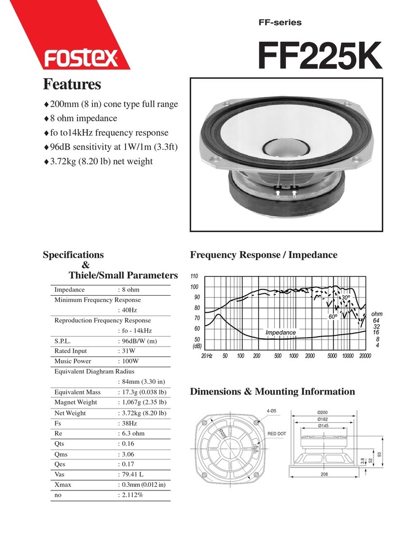
Fostex FF225K User manual
Fostex
Fostex P650-E User manual

Fostex
Fostex FE83En User manual
Fostex
Fostex PX-5HS User manual
Fostex
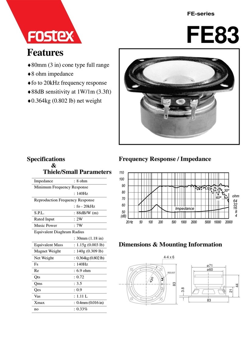
Fostex FE83 User manual

Fostex
Fostex FE206En User manual

Fostex
Fostex PX-5HS User manual
