12 13
FOXFURY WITH RESPECT TO
THIS PRODUCT. TO THE EXTENT
ALLOWED BY APPLICABLE LAW,
THERE ARE NO REPRESENTATIONS
OR WARRANTIES OF ANY KIND
BY THE FOXFURY, EXPRESS OR
IMPLIED, WITH RESPECT TO THE
CONDITION OR PERFORMANCE OF
THIS PRODUCT, INCLUDING, BUT
NOT LIMITED TO, MERCHANTABILITY
OR FITNESS FOR A PARTICULAR
PURPOSE.
THIS LIMITED WARRANTY SHALL
NOT APPLY IF THIS PRODUCT IS
NOT STORED, HANDLED, INSTALLED
OR USED IN STRICT ACCORDANCE
WITH MANUFACTURER’S
SPECIFICATIONS AND INSTRUCTION
MANUALS, OR WHICH HAS BEEN
SUBJECT TO MISUSE, ALTERATION,
NEGLIGENCE OR ACCIDENT.
1. The damaged part or product must
be returned to FoxFury PRIOR TO
any repair or replacement. Shipping
costs are the responsibility of the
claimant.
2. You must obtain a return
authorization (RMA) number from
FoxFury prior to returning products.
FoxFury is not responsible for any
damage incurred while in transit.
3. Buyer will be required to
show proof of purchase—NO
EXCEPTIONS.
4. Any modifications to light, cable or
battery pack automatically voids all
warranties on this product.
All warranty inquiries should be directed
to FoxFury’s Customer Service
Department at Service@FoxFury.com
to handle all warranty/repair-related
inquiries.
TO THE EXTENT ALLOWED BY
APPLICABLE LAW: (A) IN NO EVENT,
WHETHER DUE TO BREACH OF
WARRANTY HEREUNDER OR ANY
OTHER CAUSE WHATSOEVER,
SHALL FOXFURY BE LIABLE FOR
OR OBLIGATED IN ANY MANNER TO
PAY CONSEQUENTIAL, INCIDENTAL
OR INDIRECT DAMAGES, INCLUDING,
BUT NOT LIMITED TO, LOSS OF
PROFITS, COST OF SUBSTITUTE
PRODUCTS AND PERSONAL
INJURY OR PROPERTY DAMAGE,
WHETHER SUCH CLAIM IS BASED
ON CONTRACT OR TORT OR ANY
OTHER THEORY OF LAW, AND
(B) FOXFURY’S ONLY DUTIES IN
CONNECTION WITH THE SALE
OF THIS PRODUCT SHALL BE TO
HONOR THE LIMITED WARRANTY
SET FORTH HEREIN. TO THE
EXTENT THAT THIS LIMITED
WARRANTY IS INCONSISTENT WITH
APPLICABLE LAW, THIS STATEMENT
SHALL BE DEEMED MODIFIED
TO BE CONSISTENT WITH SUCH
APPLICABLE LAW.
CONTACT FOXFURY
FoxFury, LLC
Oceanside, CA 92056 USA
Toll-Free: 844-FOXFURY
Tel: 760.945.4231
Fax: 760.433.3650
Email: Service@FoxFury.com
Web: FoxFury.com
All FoxFury products are designed in
Oceanside, CA. All FoxFury products
are manufactured with the highest
quality USA and foreign parts. Products
are assembled in either FoxFury’s
controlled plant in Asia or the USA,
under strict quality control.
PRODUCT DURABILITY
PRODUCT NAME: Rugo™
MODEL NUMBER: 700-300
ADAPTOR INPUT: AC 100-240V,
50/60 Hz
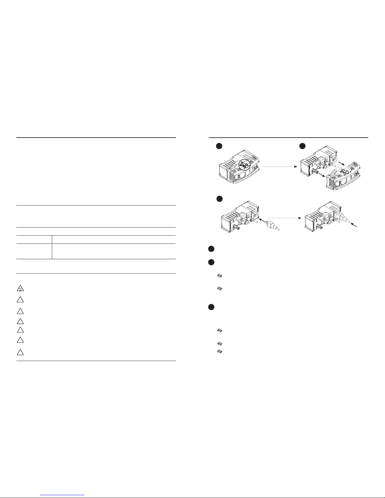
CARE/CLEANING
Your FoxFury product is a professional
tool. Regular maintenance and care of
your light will maximize performance for
you. As needed, wash your FoxFury
product using a soft washcloth, clean
water and a mild soap. Be sure that
both the Light Head and Power Pack
are reassembled securely before
washing. When done, pat dry with a
damp cloth.
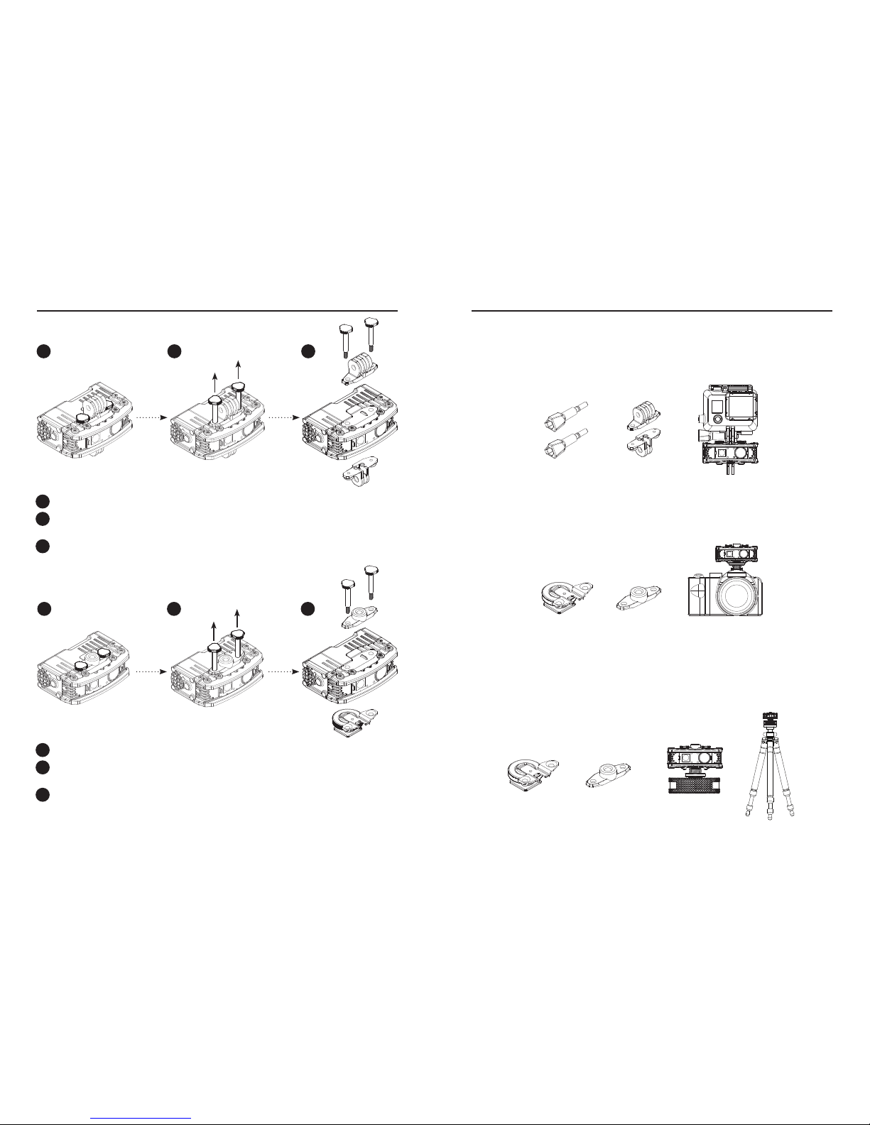
AVAILABLE ACCESSORIES
Puck Adaptor, P/N 85-045
Tripo-Scope® M1, P/N 650-100
Rugo Quick Swap™Power Pack
P/N N50-200
Rugo Standard Mount
P/N N50-132
Rugo ¼"-20 and Cold Shoe Mount
P/N N50-133
Handlebar/Drone Mount
P/N 85-026
WARNINGS
FoxFury, LLC is not responsible for the
incorrect use of any FoxFury Lighting
product.
When used for extended periods of
time the Rugo™will become HOT
to the touch. Please use care when
operating.
Lights are strong enough to cause
damage to the human eye.
Do not stare into LEDs for long
periods of time or from a close
range (less than 2 ft).
FoxFury, LLC is not responsible
for any injury or damage caused
during the use of this product.
Usage of this product must be
supervised by an adult when it is
being used by a minor.
Any FoxFury product should
be operated at speeds safe
enough to maneuver around
surrounding obstacles.
Do not use under the influence
of drugs or alcohol.
LIMITED WARRANTY
FoxFury, LLC (“FoxFury”) warrants to
the purchaser of this product (“Buyer”)
that for a period of TWO YEARS
following purchase, this product will
be free from defects in material and
workmanship and will function in
substantial compliance with FoxFury’s
written specifications for this product
as specified in the instruction manual
or on FoxFury’s website located at
www.FoxFury.com. Buyer’s exclusive
remedy shall, in any case, be limited,
at FoxFury’s election, to: A) repair or
replacement of the defective product; or
B) refund of the purchase price for this
product.
THE FOREGOING WARRANTY IS
THE ONLY WARRANTY MADE BY
WARRANTY AND OTHER
INFORMATION
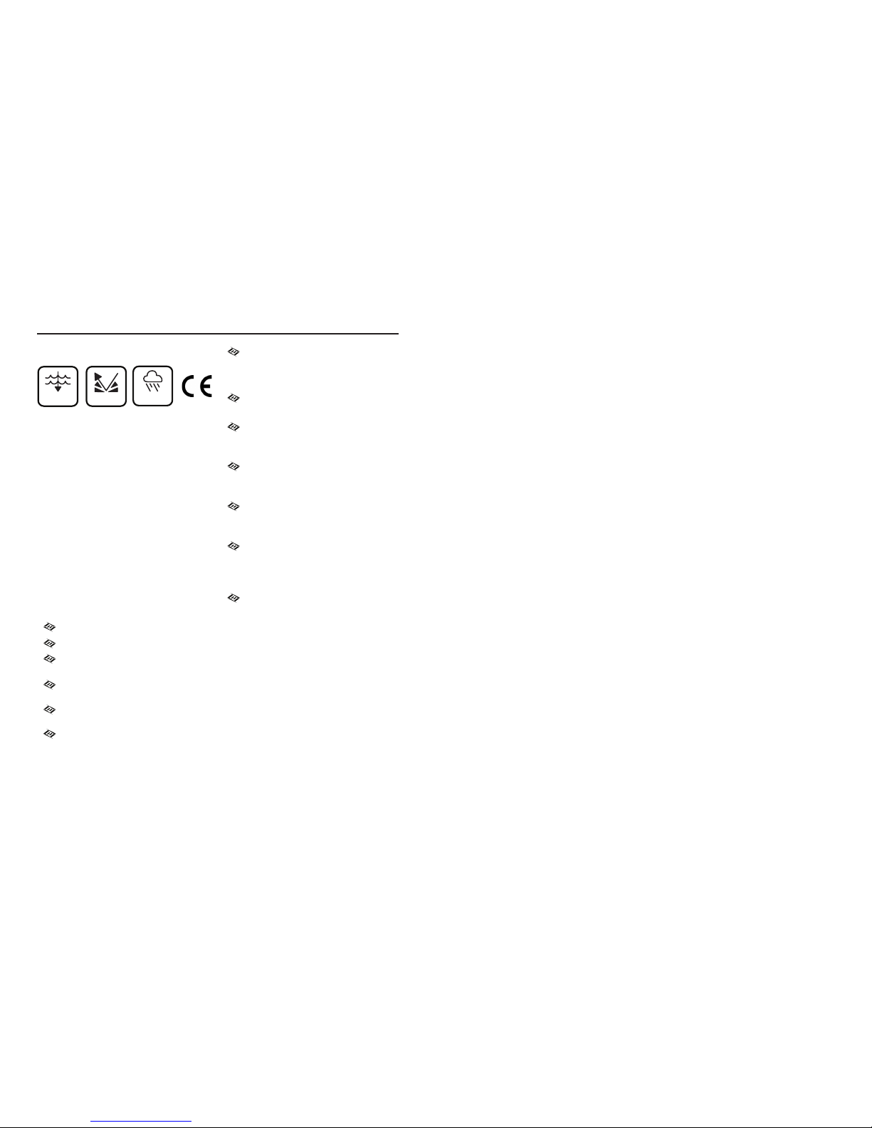
IPX7
20 M 3 M