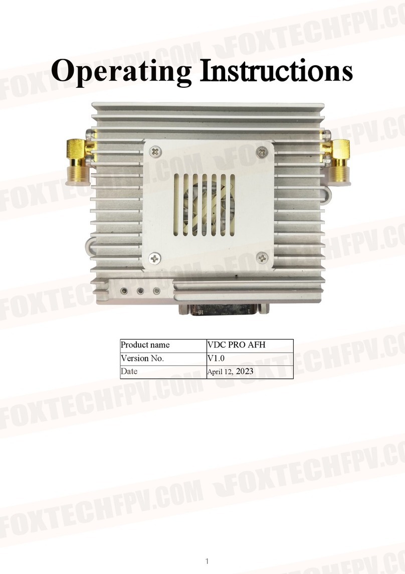
Foxtech VDC-30 User manual

User Manual
V1.0
VDC-30
Long Range Video/Data/RC
Wireless Transmission System
2020.04

Disclaimer
- Please read the user's manual carefully before use. Be sure to pay attention to the warnings and
understand all points completely.
- Please strictly abide by the local radio frequency management regulations.
- Please follow the installation steps in the manual to use this product. Our company and agent will
not take legal responsibility for the damage of equipment or personnel caused by the installation and
modification of users.
- This copyright of this manual belongs to Foxtech. No one may make copies without written consent.
Caution
Attention to installation
1.Before power on, make sure the antenna connection is reliably . Otherwise, it will cause damage to the
device.
2.Make sure that the voltage is within the range of use.
3.Please pay attention to the EMC of all the electronic equipments on your drone.
4.It is recommended that the antenna should be installed downward and keep the antenna away from the
metal on the drone.
5.Make sure to use the matching antenna.
Before use
1.Make sure that all cables are connected correctly and firmly.
2.No foreign objects (e.g. liquids, sand, etc.) can be entered inside the device.
3.It takes 15 seconds for the device to start. Video and data cannot be transferred until the device has
finished booting.
4.Please ensure that the environment in which the equipment is used is free of other electromagnetic
interference.
5.When the signal weakens, you can improve the effect by changing the heading direction of the
antenna.

VDC-30 Long Range Video/Data/RC Wireless Transmission System User Manual
©2020 FOXTECH All Rights Reserved 3
Packing List
Overview
Features
VDC-30 Interface Description
Installation
Air
Ground
VDC-30 Instruction
Quick Start
VDC-30 CODEC Module JM30
VDC-30 with Mission Planner
Improve RC controller distance through SBUS
Maestro Assistant
Interface of Maestro Assistant
How to use Maestro Assistant
VDC-30 Web UI Conguration Description
Login
Settings
Wireless Parameter Setting
System Update
System Operation
Specication
FAQ
4
5
6
7
9
9
9
10
10
11
11
14
15
15
16
18
18
18
20
21
21
22
23
Contents

VDC-30 Long Range Video/Data/RC Wireless Transmission System User Manual
©2020 FOXTECH All Rights Reserved 4
Packing List
Accessories
Fiber-glass antenna X 2
For ground unit
Antenna ×x2
For air unit
Device X 2
2Pin XT30 cable X 2
For Power
3Pin cable X 6
For UART and SBUS
7Pin cable X2
For Ethernet and Power_Out
4Pin cable X2
For Ethernet

VDC-30 Long Range Video/Data/RC Wireless Transmission System User Manual
©2020 FOXTECH All Rights Reserved 5
Overview
Industry drone market is developing very fast in recent years. The fight time and distance of drones are
getting longer and longer. VDC-30, a long-range wireless transmission system, is designed for VTOL fixed
wing and other long-range drones. The system can transmit video, fight control data, gimbal control data,
and RC data simultaneously. With the advantage of high level intergration and powerful function, VDC-30 is
a typical good product to meet long-range transmission requirements.
There are three ethernet ports in VDC-30. Users can connect it to ethernet gimbal and other payload
simultaneously. If you want to connect HDMI/SDI/AV port payload, we have MF05×MF08 to meet your
needs. You only need one single switching cable to connect VDC-30 and MF05. And the switching cable is
in the accessory box. For more information, please refer to the relevant section below. There are two UART
port——UART1 and UART2. Two protocols, Mavlink and Transparent, are supported. Users can make
changes easily through Maestro Assitant or Webpage. There are two SBUS——SBUS_IN and SBUS_OUT
for RC data transmission.
There are two frequency bands——800MHz and 1.4GHz. Users can choose according to their needs.
Please choose the suitable frequency band according to local regulations.
The weight of VDC-30 is 143g, making it very suitable for long-range drones. With advanced radio
frequency and encryption technology, VDC-30 can achieve long distance secure transmission. The maxium
transmission distance of VDC-30 can reach 34km*1.
We are going to open up the SDK in VDC-30 platform. Users can easily complete secondary development.
For more information of SDK, please follow our official website. The software SDK and examples will be
continuously updated.
*1 Test under LOS and no interference conditions.

VDC-30 Long Range Video/Data/RC Wireless Transmission System User Manual
©2020 FOXTECH All Rights Reserved 6
Features
Long distance
-Up to 34km @ LOS
Video interface
- Ethernet *3
Hopping/Fixed Frequency
-Fixed: user defined
-Hopping: automatic
BW
-3/5/10/20 MHz
Work temperature
- 40℃~ +70℃
Modulation
- OFDM
Data interface
- UART×TTL/RS232×/SBUS×
Frequency Band
- 800MHz/1.4GHz
Working mode
- Air unit can be ×Point to point mode
Power range
- DC 9~28V Battery 3S~6S

VDC-30 Long Range Video/Data/RC Wireless Transmission System User Manual
©2020 FOXTECH All Rights Reserved 7
VDC-30 Interface Description
1.Power indicator
This indicator is solid green when air unit is booting.
2.Link indicator
solid green: Wireless link is established
light off: Wireless link is lost
3.Status Indicator
Blink 2 times: Initialization OK, Frequency is 1.4G
Blink 1 time: Initialization OK, Frequency is 800M
Blink 3 times: Switch mode (Swith from air to ground, vice verse)
Blink slow all the time: Enter configuration mode
Blink fast all the time: Device abnormal
4.RSSI Indicator
3 solid green: Wireless signal is strong
2 solid green: Wireless signal is medium
1 solid green: Wireless signal is weak
all LED turn off: No wireless signal
5.Ethernet and DC out.
6.Ethernet

VDC-30 Long Range Video/Data/RC Wireless Transmission System User Manual
©2020 FOXTECH All Rights Reserved 8
7.Two SMA antenna interface
8.Power interface
9.RJ45 Ethernet
10.SBUS OUT
11.SBUS IN
12.UART2
13.UART1
14.Mode switch
The swith in the side of “A”means “air” and in the side of “G”means “ground”.
Attention×When two VDC-30 devices can not link, please check the Mode swith first.
15.Button
Press 10 seconds, air unit will restore all parameters to factory setting×

VDC-30 Long Range Video/Data/RC Wireless Transmission System User Manual
©2020 FOXTECH All Rights Reserved 9
Installation
Air
Ground
1.Installing the air unit on your drone
Fixed the device and RF cable on your drone. Install the antenna. Pay attention to the connection of the
antenna to tighten. Make the antenna downward. There is no metal or shielding within 20cm of the antenna.
2.Connecting the gimbal
Connect the gimbal to one ethernet of VDC-30. Connect UART1 to flight control. If you need to control the
drone with RC, please connect SBUS_OUT of VDC-30 to flight control SBUS IN.
Attention: If your gimbal only has HDMI/SDI/AV interface, please refer to the section of “VDC-30 with M05E”.
Do not put the antenna near the motor or ESC, otherwise the device will be interfered.
1.Connect the antenna
Connect the fiber glass antenna which was supplied along with the device to the ground unit. They have
common port—SMA. Make sure to tighten the joint. The 2 fiber glass antenna should be 1.5m apart.
Connect the RC receiver and other cables.
Connect the RC receiver SBUS output to the ground unit
SBUS_IN and then connect the power cable.
2.Connect to the Ground Station
The VDC-30 ground station can be connected to the
Ground Station with ethernet or UART.
Get Video
You can get video via RTSP, and decode the video with
video decoding software such as VLC. Also, you can get
video using Mission Planner and QGC.
Get data
1.You can get data from ground unit via UART1 and
UART2. Maybe you need a UART to
USB converter.
2.You can get data from Ethernet port using UDP/TCP
protocol.

VDC-30 Long Range Video/Data/RC Wireless Transmission System User Manual
©2020 FOXTECH All Rights Reserved 10
VDC-30 Instruction
Quick Start
1.Preparing
Make sure all the connections are ready, including the antenna, Ethernet cable and so on.If you connect a
ethernet gimbal to VDC-30 air unit, the GH1.25 interface is recommended for high reliability.
2.Power on
The DC voltage is 9~28V. After power on, the POWER LED will be solid green.
Any question, please refer to the FAQ. It takes 15 seconds to start up. After the system starts, the wireless
transmission can be established.
3.Using PC to get video from ethernet gimbal.
Connect gimbal×VDC-30 and PC as shown above×
Attention×Please ensure that gimbal and PC on the same network segment. The default IP of VDC-30 is
in the table below. The network segment of gimbal and M52 can be different. VDC-30 can transparently
transmit video and data.
VDC-30 air unit default IP 192.168.1.200
VDC-30 ground unit default IP 192.168.1.236
Get video
User can get video in PC through
the software provided by the gimbal
manufacturer.
Also, user can use some common software
such as VLC. Take VLC for an example.
In the “open media” page, please input the
following address× rtsp://192.168.1.36:554/
stream0
You can get video after click “play”.

VDC-30 Long Range Video/Data/RC Wireless Transmission System User Manual
©2020 FOXTECH All Rights Reserved 11
VDC-30 CODEC Module JM30
VDC-30 with Mission Planner
If your gimbal has a HDMI/SDI/AV interface, you can add CODEC module JM30 to work with VDC-30. JM30
contains encoding module JM30E and decoding module JM30D. You only need one single cable in the
accessory box to connect VDC-30 and JM30. It is shown in the picture below.
For more information, please refer to the JM30 user's manual.
Follow the steps to use VDC-30 with Mission Planner×
1.Connect the UART1 of VDC-30 air unit to flight controller, such
as Pixhawk. Connect the gimbal to one ethernet of VDC-30.
2.Making sure all the air and ground cable connection is finished.
Power on the system.
3.Install Mission Planner to your computer.
4.Set the IP address of the computer.
Open “Network and Internet”setting.
Select “Internet Protocol version 4 (TCP / IPv4) properties”.
Change IP address to “192.168.1.xxx”×xxx is in 0×255 , you
cann’t use IP 192.168.1.200 and 192.168.1.236, because these
IP were set in VDC-30×.
Attention×The IP “192.168.1.XXX”is just an example. You
need to set up your PC the same IP section as your gimbal.
5.Get data
There are three methods to get data from VDC-30 ground unit, using Mission Planner×
- UDP port via Ethernet;
- TCP port via Ethernet×
- UART (COM)
Get data from UDP port.

VDC-30 Long Range Video/Data/RC Wireless Transmission System User Manual
©2020 FOXTECH All Rights Reserved 12
Open Mission Planner×select UDP×click the “connect” button, it will bring up a new window ‘Listen port’×
change the port to 14550×If the UDP port number has been changed on the web page, please fill in the new
number. For more information, please go to the web
page configuration×.Then click “OK”, Mission Planner will get flight data×
Get data from TCP port.
Open Mission Planner×select TCP×click the “connect” button, it will bring up a new window ‘Listen port’×fill
in the blank with IP: 192.168.1.236, remote port is 5760
×If the IP address and TCP port number has been changed on the web page, please fill in the new IP and
port number. For more information, please go to the web page configuration×.Then click “OK”, Mission
Planner will get flight data.
Get data from UART(COM)×
Connect the ground unit UART1 with a UART×TTL× to USB
converter to the computer. Before this, please
install the driver in the computer.

VDC-30 Long Range Video/Data/RC Wireless Transmission System User Manual
©2020 FOXTECH All Rights Reserved 13
Open Mission Planner, select COM (Please check the COM number) and the right baud
rate×click the “connect” button, Mission Planner will get flight data.
6.Get video
When you open the Mission Planner, click Video and then Set GStream Source×as show below×
Input the address: rtspsrc location=rtsp://192.168.1.36/stream0 latency=0 decodebin videoconvert video/
x-raw,format=BGRA appsink name=outsink
Attention: The IP“192.168.1.36/stream0”is an example of the gimbal, please use
your own gimbal RTSP address.

VDC-30 Long Range Video/Data/RC Wireless Transmission System User Manual
©2020 FOXTECH All Rights Reserved 14
Improve RC controller distance through SBUS
1.Connect air unit SBUS_OUT to flight controller RC IN.
Using the SBUS cable in the accessory box to connect the air unit and the flight controller. The cable is 3
pin.
Attention×The SBUS_OUT port of air unit is output. The maximum of +5V output current is 1A. If you
don’t need the +5V, let it open. Do not take it as input. Otherwise, the stability of the system will be
affected.
2.Connect the RC receiver to the ground unit
Using the SBUS cable in the accessory box to connect the ground unit to the RC receiver.
Attention×The SBUS_IN port of ground unit is input. The maximum of +5V output current is 1A. You
can use it to power the RC receiver. Please pay more attention to the cable line order.

VDC-30 Long Range Video/Data/RC Wireless Transmission System User Manual
©2020 FOXTECH All Rights Reserved 15
Maestro Assistant
Interface of Maestro Assistant
Function description×
×1×Information display×display status information for the VDC-30×
×2×UART(COM) select×Select the right COM number of the computer to connect VDC-30. If you want to
change to another COM , please click the ‘Refresh’ button.
×3×Baud rate select×Select the right baud rate for the COM. Make it the same as VDC-30 UART1.
×4×Open COM button.
×5×Close COM button.
×6×Read current parameter button×click this button to get the current parameter of device×
×7×Clear window button: to clear the information display.
×8×Select frequency×The VDC-30 frequency band has been set. User cann’t change. You can click
‘Get’button to get current frequency band.
×9×Select BW×There are four BW to be selected——3MHz/5MHz/10MHz/20MHz. Choose the BW you
needed×and click ‘Set’ button to complete setup. Click the ‘Get’ button to get current BW.
10×Select Power Level×There are three power level to be selected——High/Mid/Low Choose the power
level you needed×and click ‘Set’ button to complete setup. Click the ‘Get’ button to get current power level.
11×Select baud rate×You can select the right baud rate for VDC-30 Uart1 in this box.
Choose the baud rate you needed×and click ‘Set’ button to complete setup. Click the ‘Get’ button to get
current baud rate.
12×Select hopping mode: There are two mode to be selected——Hopping/Fixed. Choose the mode you
needed×and click ‘Set’ button to complete setup. Click the ‘Get’ button to get mode.
When you select Fixed mode, you need to choose a fixed frequency below. The fixed frequency is related
to frequency band and BW.
13×Select Encryption: You can disable/enable the encryption. When enable this function, you
can set your private password. The password should in the range of 100000~999999. Devices with different
password do not link.

VDC-30 Long Range Video/Data/RC Wireless Transmission System User Manual
©2020 FOXTECH All Rights Reserved 16
14×Select Working mode: There are two working mode of VDC-30——Point to Point mode and
Repeater mode. Choose the working mode you needed×and click ‘Set’ button to complete setup. Click the
‘Get’ button to get current working mode. This function only needs to be set up on the
M51 air unit. The ground unit can synchronize automatically. If you select Repeater mode, you need to
select the air unit whether it is TX or repeater.
How to use Maestro Assistant
1.Connect VDC-30 with Maestro Assistant×
Maestro Assistant is a Windows software that configures VDC-30. Before configuration, please connect the
UART1 to computer via UART(TTL) to USB converter.
Select the right COM and baud rate. Click ‘open’ button.
2.Read current parameter×
After step1, click ‘Read’ button. All current parameter will print on the information display. Because the
Working mode is only for air unit. The Working mode box will turn grey on ground unit configuration.
Frequency Band
The VDC-30 frequency band has been set. User can not change.
You can click ‘Get’button to get current frequency band.
Bandwidth
There are four BW to be selected——3MHz/ 5MHz/10MHz/20MHz.
The greater the BW, the more
data can be transmitted, but the weaker the
anti-interference. In Fixed frequency mode, VDC-30 will have more
frequency to fix with small BW.

VDC-30 Long Range Video/Data/RC Wireless Transmission System User Manual
©2020 FOXTECH All Rights Reserved 17
RF Power
VDC-30 has three levels of power to choose.
In order to avoid affecting other devices, please
select the appropriate transmission power. The specific RF power values are
as follow
1-Low×20dBm×
2-Mid×27dBm× 3-High×32dBm×
Hopping/Fixed Mode
There are two mode to be selected——Hopping
/Fixed. In Hopping mode, M51 can automatically adjust frequency when there
is interference. In fixed mode, the device is fixed to a special frequency . So
in one frequency band, up to four sets of devices can be used.
Encryption
The wireless signal can be encrypted during transmission. When enable this
function, you can set your private password.
The password should in the range of 100000~999999. Devices with different
password do not link. When disable this function, different VDC-30 air and
ground can link each other.×
Working Mode
VDC-30 can work in Point to Point Mode and Repeater Mode. Only the air unit
of VDC-30 need to be set. The ground unit can synchronize automatically. In
Repeater mode, the air unit can be set to TX (transmitter) or Repeater.
Air Point to Point Ground
TX Repeater Ground
Repeater Mode
With Repeater mode, VDC-30 can be easily used under NLOS situation. You only need to buy one more air
unit and then can establish a repeater system easily.

VDC-30 Long Range Video/Data/RC Wireless Transmission System User Manual
©2020 FOXTECH All Rights Reserved 18
VDC-30 Web UI Conguration Description
Parameter of VDC-30 can also be set through web UI. User can enter IP address through the browser to
access the web UI. The air unit default IP is 192.168.1.200. The ground is 192.168.1.236. In Repeater mode.
TX is 192.168.1.200. Repeater is 192.168.1.201.
If you change the device to another IP address, please access the web UI through the new IP. If you forget
the IP you changed, press the button on the device for 10 seconds when the device is power on to restore
to factory settings.
You need to change your computer IP to 192.168.1.X so as to access the device web UI. As shown in the
following figure×
Login
Settings
After you enter IP address in the browser, you will see the ‘Welcome’ page. Default username is: admin,
password is: 123456. Then you can login.

VDC-30 Long Range Video/Data/RC Wireless Transmission System User Manual
©2020 FOXTECH All Rights Reserved 19
In Air setting page, user can change air IP × Gateway and other parameter. You can refer to the table below.
If you change the device parameter, it will be in effect after rebooting. If you change IP address, please
enter the new address in your browser after rebooting.
If you change the device parameter, it will be in effect after rebooting. If you change IP address, please
enter the new address in your browser after rebooting.

VDC-30 Long Range Video/Data/RC Wireless Transmission System User Manual
©2020 FOXTECH All Rights Reserved 20
Wireless Parameter Setting
User can change wireless parameter on Wireless Parameter setting page . You can refer to the table below.
Web UI configuration is the same as Maestro Assistant. User can check it in ‘How to use Maestro Assistant’
part 3 for more details.
When you configure parameter through Web UI, It will be in effect after rebooting
This manual suits for next models
1
Table of contents
Other Foxtech Microphone System manuals