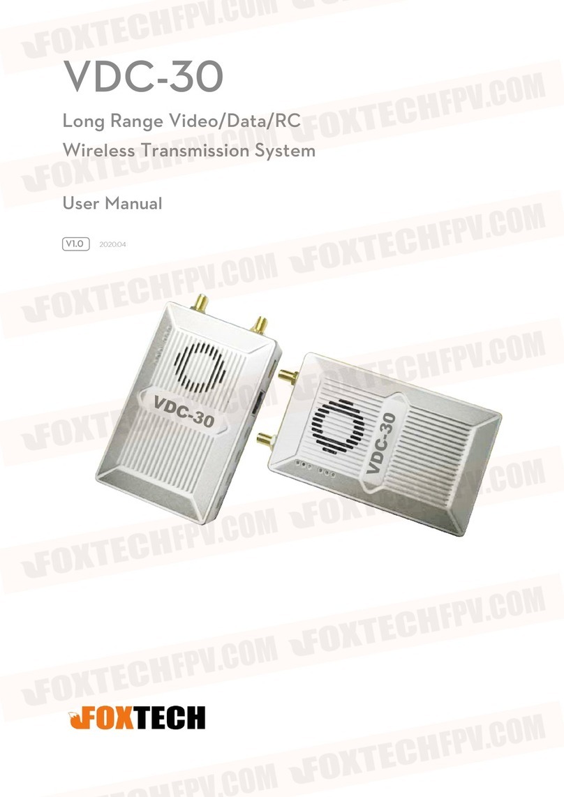
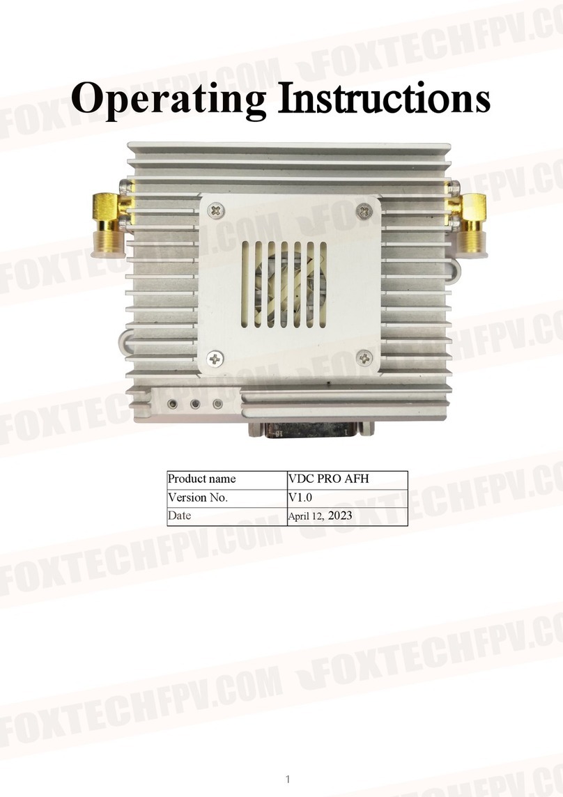
Foxtech VDC-22 User manual

VDC-22 / VDC-55
Long-Range Video / Data Transmission System
V1.0 2022.10

Description
Disclaimer
Thank you for purchasing this product. you can log in to the website for the latest product
information, technical support and user manual. It is recommended that you download and
use the latest version of the user manual. This manual is subject to change without
notice.
You can also get product usage information or technical support through official customer
service. Due to different production batches, the appearance or function parameters are
slightly different and will not affect the normal use of the product.
Please read this statement carefully before using. Once used, it is deemed to be an
endorsement and acceptance of the entire contents of this statement. Please read the
instruction manual carefully and strictly follow the instructions in this manual to use this
product. Foxtech will not be liable for any result or loss caused by improper use,
installation, assembly or modification of users.
Intellectual Property
The intellectual property rights of this product and manual are owned by Foxtech. Any
organization or individual may not copy, reproduce or distribute in any form without written
permission. If you need to quote, you need to indicate the source, and you should not make
any modifications, deletions and references to this manual.

Mounting Precaution
1. Please make sure that the mounting between the antenna and the device are
tight, or the device will be damaged;
2. Please make sure the input voltage is acceptable, or the device will be
damaged;
3. Please make sure the antenna of the air unit is face toward the ground
vertically and avoid blocks, or the transmission signal will be affected and
shorten the distance;
4. The mounting location should try to avoid metal parts, and it is better to keep
a 20-cm-clear-area around the antenna;
5. Use the antenna designated by the manufacture to ensure the frequency and
impedance;
6. Please make sure there is appropriate distance between modules to minimum
the electromagnetic interference.
Using Precaution
1. Please sure all the connection are firm and tight;
2. Make sure there is no object inside the equipment;
3. It needs about 15 s after powering up to start to work, then data transmission
is available;
4. Please make sure there is no high-powered wireless emitting equipment with
the same frequency around where VDC-22 / VDC-55 is working, or the image
receiving will be affected and damaged;
5. If the receive signal is bad, adjust the angle of the receive antenna may help.
Download Maestro Assistant:
https://www.foxtechfpv.com/product/Long-range-Transmission-System/VDC-22-VDC-55-
Software.zip

Content
Package......................................................................................................................... 1
Short Description............................................................................................................ 2
Main Parameters............................................................................................................ 3
Interface......................................................................................................................... 4
Mounting ........................................................................................................................ 9
Sky End..................................................................................................................9
Base End................................................................................................................10
1. Antenna And Wire..................................................................................... 10
2. GCS.......................................................................................................... 10
Specification................................................................................................................... 11

Package
Device
Base End Sky End
Standard Accessories
Feeder Cables *1 Power / SBus Cable *1
Sky End Antenna *4
(2.5 dBi & 4 dBi) Fiberglass Antenna *1
VDC-22 / VDC-55 User Manual
©2022 FOXTECH All Rights Reserved 1

Short Description
VDC-22 / VDC-55 is a long-range transmission system with video /data / SBus signal
transmission all-in-one, which features handy, powerful and high integration. The integrated
design of the ground side makes it very easy to use.
VDC-22 / VDC-55 have three optional frequency bands: 800MHz, 1.4GHz and 2.4GHz,
which can be purchased and used by users according to their needs, and please obey local
radio control regulations when using it.
The transmission distance of VDC-22 reaches 22km, and the transmission distance of
VDC-55 reaches 55km. The integrated link makes the UAV operation more concise, and the
ground end does not need to set up antenna specially, which shortens the operation
preparation time. The good industrial thermal design enables it to meet the needs of
industry-grade applications.
VDC-22 / VDC-55 can connect with GCS which supports aviation plug, so please reach to
our sales if you need.
VDC-22 / VDC-55 User Manual
©2022 FOXTECH All Rights Reserved 2
*Test under LOS and no interference conditions.

Main Parameters
Transmission Distance
22 km for VDC-22
55 km for VDC-55
Video Transmission
1* Ethernet Port
Frequency Modulation
Frequency Hopping / Fixed Frequency
Working Bandwidth
5/10/20 MHz
Working Temperature
40℃~+70℃
Modulation Mode
OFDM
Data Transmission
2*UART / 2* SBUS
multi-channel transmission is support
Working Frequency
800 MHz / 1.4 GHz / 2.4 GHz
Working Mode
Air Unit: Point-to-Point
Relay Mode
Power Input
9~28V DC
3S~6S Battery
VDC-22 / VDC-55 User Manual
©2022 FOXTECH All Rights Reserved 3

Interface
Sky End
1. Ethernet
No. Symbol Description Direction
1 T+ TX+ O
2 T- TX- O
3 R+ RX+ I
4 R- RX- I
2. UART1
No. Symbol Description Direction
1 G GND I/O
2 R RS232 RX I
3 T RS232 TX O
VDC-22 / VDC-55 User Manual
©2022 FOXTECH All Rights Reserved 4

3. UART2
1 G GND O
2 R TTL RX I
3 T TTL TX O
4. Power
1 G GND I/O
2 V +Vcc (9v~28v)I
5. SBUS1
1 S SBUS OUT O
2 V +5v (Max Current 1A)O
3 G GND I/O
6. SBUS2
1 S SBUS OUT O
2 V +5v (Max Current 1A)O
3 G GND I/O
No. Symbol Description Direction
7. Status Indicator
Green Light State
Flash Twice
Flash Once
Initiating succeed, at 1.4 GHz frequency
Initiating succeed, at 800 MHz frequency
Flash Thrice Quickly Mode changing succeed
Flash Slowly Enter setting mode
Flash Quickly & Constantly Working abnormally
Constantly On Wireless connection succeed
Off Wireless connection failed
VDC-22 / VDC-55 User Manual
©2022 FOXTECH All Rights Reserved 5

8.WI-Fi Signal Strength
Green Light State
3 Lights Constantly On Signal strength is strong, transmission quality is high
2 Lights Constantly On Signal strength is OK, transmission quality is medium
1 Light Constantly On Signal strength is weak, transmission quality is low
Off No signal / connection is fail
10. SMA Antenna Port
VDC-22 / VDC-55 User Manual
©2022 FOXTECH All Rights Reserved 6
9. Power indicator
This indicator is solid green when air unit is booting.

1. Fiberglass antenna
2. Signal display screen
Display signal strength, frequency, bandwidth, etc.
Five LED lights stands for Power, Connection and Signal Strength
3. Battery Base
SONY XXXX Battery is acceptable. Exterior power supply is preferred if an exterior
power supply is connected via interface No. 4.
4. Aviation plug
Base End
The aviation plug contains Ethernet, serial port, SBus, power, etc. and the specific
definition is as follow:
VDC-22 / VDC-55 User Manual
©2022 FOXTECH All Rights Reserved 7

No. Description Direction
1 Rx+ I
2 Rx- I
3 Tx+ O
4 Tx- O
5 UART1 TX (RS232) O
6 UART1 RX (RS232) I
7 UART2 TX (RS232) O
8 UART2 RX (RS232) I
9 NC NC
10 RC1_IN I
11 RC2_IN I
12 +5v O
13 GND I/O
14 GND I/O
15 GND I/O
16 GND I/O
17 GND I/O
18 GND I/O
19 Vcc (9v~28v) I
20 Vcc (9v~28v) I
VDC-22 / VDC-55 User Manual
©2022 FOXTECH All Rights Reserved 8

Mounting
Sky End Mounting
Install the sky end on the UAV and mount the antenna. Make sure the SMA
interface is tightened. The transmission quality will be the best when the antenna faces
down vertically without metal objects around it within 20 cm and avoid block caused by
the body.
1. Mount Antenna
2. Connect gimbal with the FC
Connect the gimbal with VDC-22 / VDC-55 via Ethernet interface and connect
the VDC-22 / VDC-55 to the FC by UART1 ( RS232 by default) and UART2 (TTL by
default). Please connect the SBUS_OUT interface on VDC-22 / VDC-55 to SBUS interface
on FC to realize RC control.
Note: If the gimbal is connected with HDMI/SDI/AV interface, a module should
be added first.
All of the signal line should try to away from wires of the motor or BEC, or
there may be interference.
VDC-22 / VDC-55 User Manual
©2022 FOXTECH All Rights Reserved 9

Base End
1. Antenna & Wire
2. GCS
The base end can connect to the GCS via Ethernet port or UART interface and send
the image and data to the ground station.
Video Display
The base end can transfer the video to the decoding software (such as VCL) on the
host computer or GCS (such as Mission Planner).
Data Transmission
The base end can sent data to the host computer via serial port using a UART
( RS232) to USB module. It also can sent the FC data to GCS via Ethernet UDP/TCP ( only
data from the sky end UART2 interface that can be forwarded by Ethernet on the base
end.
VDC-22 / VDC-55 User Manual
©2022 FOXTECH All Rights Reserved 10

Specification
Wireless
Performance
Bandwidth 800MHz / 1.4GHz / 2.4GHz
Working
Bandwidth
800MHz: 806MHz~825MHz
1.4GHz: 1427MHz~1447MHz
2.4GHz: 2408MHz~2488MHz
Channel
Bandwidth 5MHz/10MHz/20MHz
Modulation Mode OFDM
Output Power MK22:30dBm±1dB
MK55:33dBm±1dB
Sensitivity ≤-95dBm
Transmission
Distance
MK22:22km
MK55:55km
Speed In The Air 30Mbps@20MHz
Power Input DC 9~28V
Power
Consumption
Interface
Antenna 2*SMA, 1*N
Power 1*XT30 Input Power
Serial Port
Air Unit: 2*UART1 RS232; UART2
TTL 3.3V level
Ground Unit: 2*UART1; UART2
RS232
≤8.5W
VDC-22 / VDC-55 User Manual
©2022 FOXTECH All Rights Reserved 11

Baud Rate: 115200 (Default),
support 57600, 38400, 19200, 9600
SBUS Air Unit: 2 *SBUS Output
Ground Unit: 2*SBUS Intput
Ethernet
Ground Unit: 1*RJ45
Antenna
Port Air Unit: SMA
Ground Unit: N
Enclosure Air Unit: Black rubber
Ground Unit: White plastic Panel
Antenna: Grey fiberglass
Tpye
Polarization Type
Air Unit: Rubber Antenna 20cm
Ground Unit: Panel
omnidirectional
25cm*25cm
Fiberglass Antenna 30cm
Gain Air Unit: 2.5dBi
Ground Unit:
Fixed:
12dBi,
omnidirectional:
5dBi
SWR ≤2.0
Environment
Working Temp
Storage Temp
Humidity 5~95%, no Condensation
Vertical
-40℃~+70℃
-40℃~+85℃
VDC-22 / VDC-55 User Manual
©2022 FOXTECH All Rights Reserved 12
Air Unit: 1*4pin
This manual suits for next models
1
Table of contents
Other Foxtech Microphone System manuals