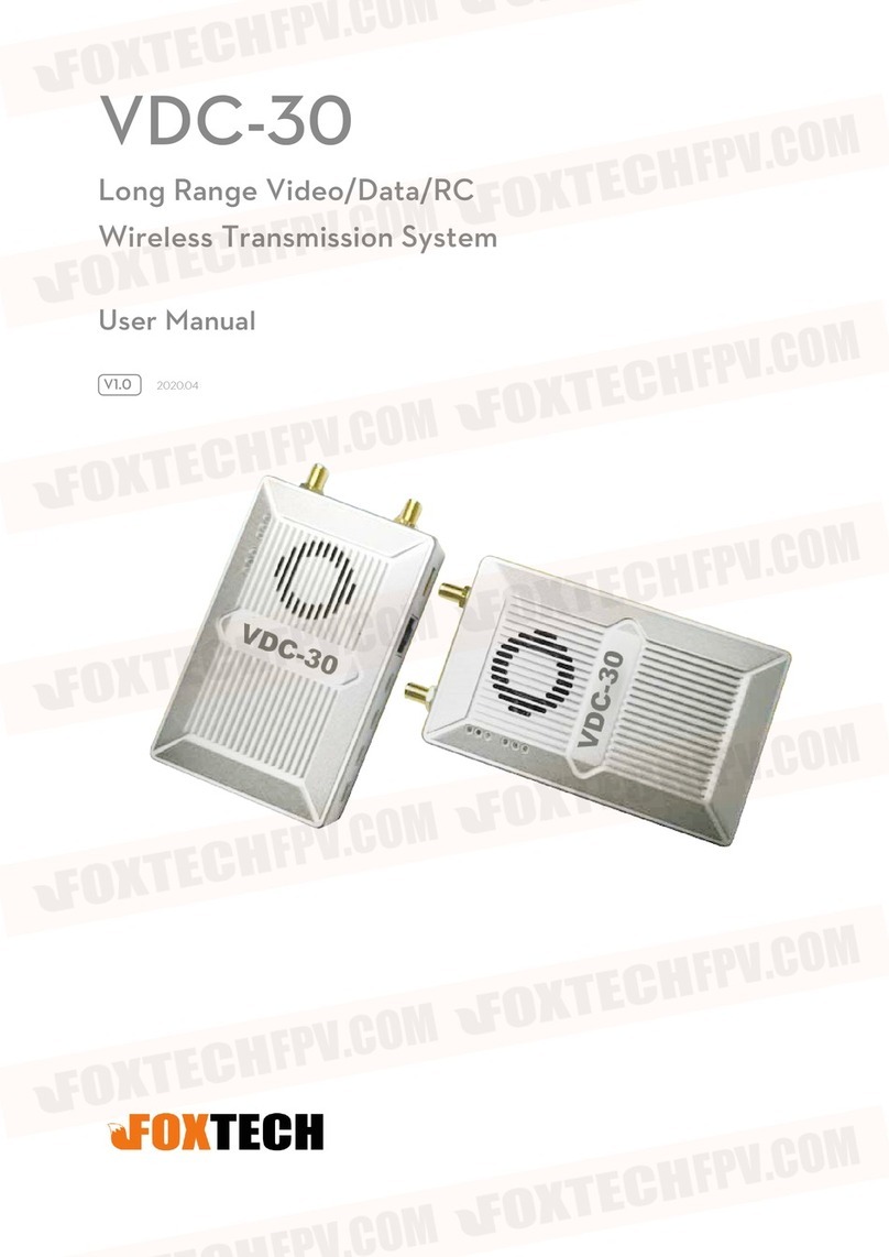
Foxtech VDC PRO AFH User manual

1
Operating Instructions
Product name VDC PRO AFH
Version No. V1.0
Date April 12, 2023

2
CONTENTS
CONTENTS ............................................................................................................................ 2
Matters needing attention ....................................................................................................... 3
Device status light ................................................................................................................... 3
Interface wire sequence .......................................................................................................... 4
Power connection .................................................................................................................... 6
Serial port connection ............................................................................................................. 6
Network port connection ........................................................................................................ 7
Debugging and configuration .................................................................................................7
Relevant parameters .............................................................................................................. 12
Solutions to common problems ............................................................................................ 12
Computer configuration network segment method.............................................................13
Typical Scheme ......................................................................................................................14

3
Matters needing attention
1) Make sure that the supply voltage is within the specified voltage range, otherwise
damage to the circuit may occur.
2) Always use the specified type of antenna and ensure that the frequency band and
other parameters match.
3) When testing indoors, the distance between the equipment must be more than 3m, too
close to the module to receive energy saturation affects the test results.
4) A minimum of 2 units are required for this unit to function properly; separate units
will not work properly.
5) Before use, the antenna must be connected before powering up, otherwise there is a
chance of burning out the equipment amplifier.
6) Typical voltage source 12V/2A Please check the voltage and current match before
powering up.
After power on, the voltage is 12V, the current is 0.4A, the power indicator is always on
(see equipment status light), and the current increases with the increase of transmitting
power.
Ensure that each group of devices has only one central node and multiple transmitter
nodes, with a central node on the handheld side and a transmitter node on the device side.
The devices in the group have the same IP network segment, the same address, the same
device secret key and the same frequency band.
In case of poor signal at either end, you can try to improve it by raising the height of the
antenna, choosing unobstructed terrain or contacting our technical support for docking.
Device status light
1. Device status light, green for master nodes and blue for slave nodes;
2. Network port light, always on when connected to the network, blinks when interacting
with data.
3. Power light, always on when the unit is powered up.
123

4
Interface wire sequence
The device uses a military-grade J30 interface.
16 1
31 17

5
The interface is defined as follows:
S/NDefinition Remark S/NDefinition Remark
1 GND 17 GND
2 USB1_DP Internal debugging and
use
18 SBUS2_OUT (Can be reused as a TTL
interface) for
network TCP data
reading
3 USB1_DM 19 SBUS2_IN
4 TTL_TX Unable to read
Network TCP data
(serial port 4)
20 SBUS1_OUT (Can be reused as a TTL
interface) for
network TCP data
reading
5 TTL_RX 21 SBUS1_IN
6 RS232_2_TX (Can be reused as
a TTL interface)for
network TCP data reading
(serial port 2)
22 TTL_RX (Can be reused
as a 485,422
interface) for
network TCP data
reading
(serial port 3)
7 RS232_2_RX 23 TTL_TX
8 GND 24 NC
9 RS232_1_TX
(Can be reused as
a TTL interface)for
network TCP data reading
(serial port 1)
25 NC
10 RS232_1_RX 26 ETH0_RX-
11 ETH1_RX- 27 ETH0_RX+
12 ETH1_RX+ 28 ETH0_TX-
13 ETH1_TX- 29 ETH0_TX+
14 ETH1_TX+ 30 VCC_12V
15 GND Power supply area shall
not be shared with the
serial port area
31 VCC_12V
16 GND

6
Power connection
Find a 12V power supply and connect it to the supplied power cable, usually 12V to pins
30 and 31 and 15 and 16 to ground.
Before connecting please check that the device antenna is screwed in, before connecting
please check whether the power supply positive and negative poles are connected
backwards, users do their own line need to pay attention to the power supply positive and
negative can not be connected backwards, otherwise it will permanently damage the
device.
Serial port connection
Serial port and pix flight control connection
Line sequences of graphical
transmission Definition
Flight
control line
sequence
Definition
5/7/10/22 RX 2 TX
4/6/9/23 TX 3 RX
1/8/17 GND 6 GND
The serial port is connected to the controller, refer to the interface definition to determine
which interface is required.
Graphical
transmission
device string
Row number
Picture
transmission
equipment
(232/TTL)
User controlled devices
(232/TTL)
5/7/10/22 RX TX
1/8/17 GND GND
4/6/9/23 TX RX

7
Network port connection
Connection with standard RJ45
Equipment line sequence RJ45 header
R- Orange and white
R+ Oran
g
e
T- Green and white
T+ Green
Connection with non-standard RJ45
Serial number of network port of
map transmission equipment
Graphical transmission
network port
Other network port devices
11/26 R- T-
12/27 R+ T+
13/28 T- R-
14/29 T+ R+
Debugging and configuration
Configure basic device attributes and functions.
Login Interface
The user has to log in to the IP address of the device (factory default IP address: 192.168.147.xx)
via the web page, enter the user name and password (both are admin) to configure the map transfer
settings.
Note: If you cannot login to the configuration screen, please check the computer configuration
network segment.

8
Configuration Interface
The user can set the device key, which is in hexadecimal (0 to 9, A to F) and can only be an even
number (each key cannot be the same when multiple sets are coexisting), up to a maximum of 64
bits;
Wireless module IP address (ip address and camera address can be different bands), wireless
module working mode (each set of equipment must have only one center, slave nodes can be ≥1) ;
Wireless module frequency band 1.4GHz optional;
Wireless module transmitting power, maximum 25, power reduction distance is not far;
Default ID4U for upstream and downstream allocation (2D3U for trunk configuration); optional
20M/I0M/5M transmission bandwidth, which is the spectrum bandwidth and not the data
bandwidth;
Real-time information which, when clicked, displays the current signal strength of the
device and the status of the link building environment when the device is building a link;
Each node needs to be modified for each set of graphical transmissions, just click on
Submit Configuration to manually re-power the device after the configuration is
complete.

9
Serial port 1 configuration is mainly for RS232/TTL serial port 1 in the wireless map transmission
data chain for related configuration.
Baud rate; setting range: 4800, 9600, 19200, 38400, 57600, 115200, 230400, 460800, 921600, the
default setting is 115200.
Check bit: NONE, ODD, EVEN, the default setting is NONE.
Data bit: 8 bit or 7 bit, the default configuration is 8 bit.
Stop bit: 1 bit or 2 bit, the default configuration is 1 bit.
Serial port 1

10
Serial port 2
The serial port 2 configuration is mainly relevant for RS232/TTL serial port 2 in the
wireless map transfer data chain.
Serial port 3
Serial port 3 configuration is mainly for RS422/485 serial port in the wireless map
transmission data chain for related configuration.

11
Serial port 4
Serial port 4 configuration is mainly for TTL serial port in the wireless map transmission
data chain for related configuration.
Sbus interface
The corresponding pins for the sbus interface are indicated in the Sbus interface.

12
Relevant parameters
RSSI: Received Signal Strength Indication. The signal saturates at a distance of -44 and decreases
as the distance increases.
RSRP: Reference signal received power. After pulling away, the RSRP-SNR will normally be less
than or equal to the value of -123.
RSRQ: Reference signal reception quality. The larger the value, the better.
SNR: Signal to thousand disturbance noise ratio. The normal state is between +25 and -20, where
a higher positive value means less signal perturbation and vice versa.
DIST: Device distance. Device spacing calculated from a period of RF transmission
supplemented by transmission speed.
Solutions to common problems
Problem Solution
The other node of the device is not working. 1. Check that the other power supply is
powered up.
2. Check whether the parameters are configured
correctly.
A. Ensure one central node and multiple access
nodes
B. Consistent access ID
C. The IP address of the device is correct
D. connected to the device of the compelling
brain ip address has been configured (computer
configuration network segment details see
Annex)
3. Check whether the access antenna is correct
and whether the equipment build chain light is
always on.
Data jams
Go to the configuration screen and check the
model snr value. A low snr value indicates a
weak signal.
Low signal for proximity devices
The signal saturated and the node did not come
up in transmit power, pulling the two nodes
apart.
Not far away.
1. Check the antenna connection cable for poor
contact.
2.Check whether the transmitting power is
changed or set too small
3. Check whether there are sources of
interference such as power supply in the whole
machine and take isolation or
shielding treatment.
4. Try raising the antenna, or replacing it with a
high gain antenna.
5. The test site is too much cover affects the test
distance meat, change the test site

13
Computer configuration network segment method.
Control Panel→Network and Internet→Network and Sharing Center→Change adapter
settings.
Find the wired network card settings connected to the device, right-click and select
Properties → double-click Internet Protocol version 4 (TCP/ IPv4) and click Use
the following IP address → Configure the IP address; IP address: 192.168.1.XXX
subnet mask: 255.255.255.0 (ip address should be the same network segment as the
device with different ip, such as the above 192.168. XXX is the ip).
Click on Confirm when finished. If you want to add a camera ip segment, please click on
Advanced Add to complete the configuration and click on the three confirmations.

14
Typical Scheme
Point-to-point solutions
1 center corresponds to 1 launch for communication.
Relay Solutions

15
Point-to-Multipoint Solution
Video Surveillance and quipment
Table of contents
Other Foxtech Microphone System manuals
Popular Microphone System manuals by other brands

Electro-Voice
Electro-Voice Wireless Guitar System GS-2000A owner's manual

Hollyland
Hollyland COSMO 1200 manual

Phoenix Audio Technologies
Phoenix Audio Technologies MT107E-HD manual

Speech Recognition Solutions
Speech Recognition Solutions SpeechWare TableMike Complete user guide

Galaxy Audio
Galaxy Audio Galaxy Trek GT-INST-6 user manual

Shure
Shure Performance Gear manual