6 - LAMPO AI- Ver. 04
D811460_04
MANUALE PER L’INSTALLAZIONE ITALIANO
INSTALLATION MANUAL ENGLISH
1) GENERALITA’
Lampeggiante di sicurezza visiva atto a segnalare il movimento di un cancello o porta automatizzata.
Il lampeggiante deve essere utilizzato solamente con le centrali di comando del costruttore.
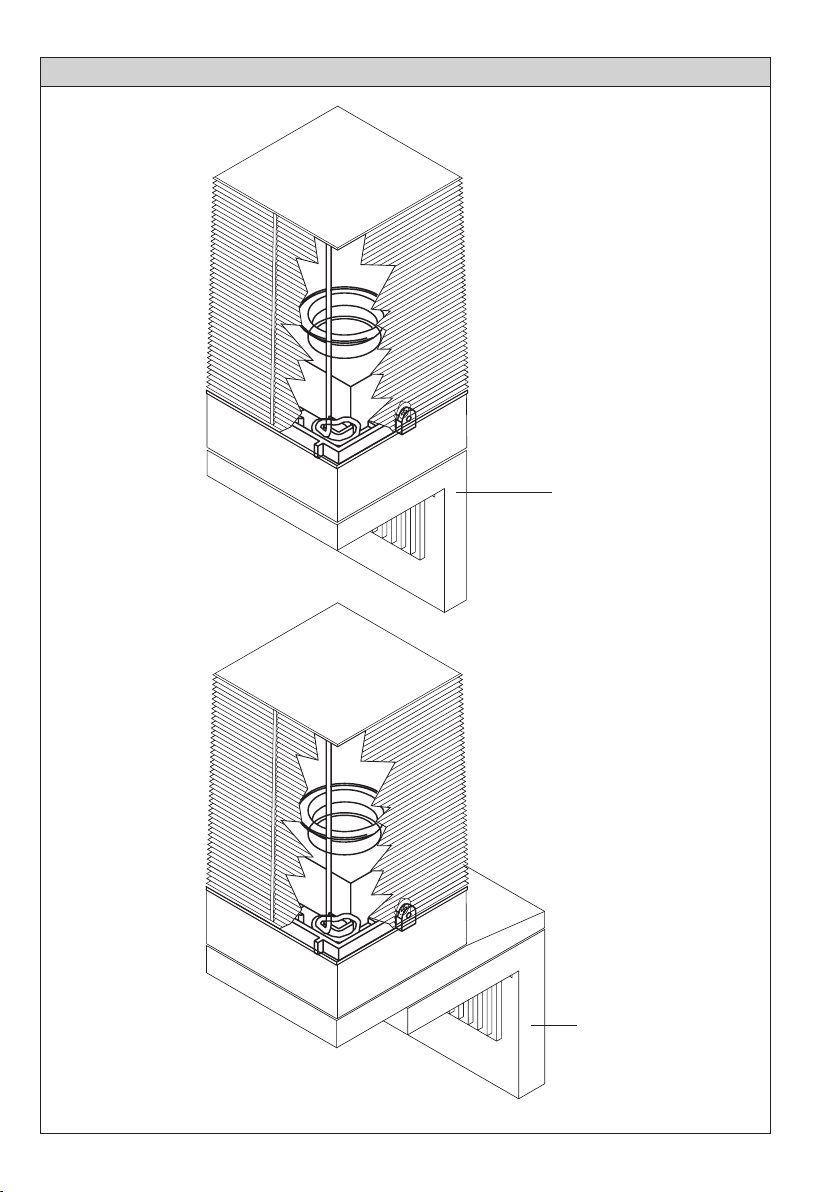
2) MONTAGGIO
a) Montaggio verticale diretto (fig.1).
b) Montaggio verticale a parete (fig.2) con supporto mod. SLM2 (accessorio)
In posizione verticale il grado di protezione è IP44.
ATTENZIONE! La presenza di masse metalliche a ridosso dell’antenna, può disturbare la ricezione radio.
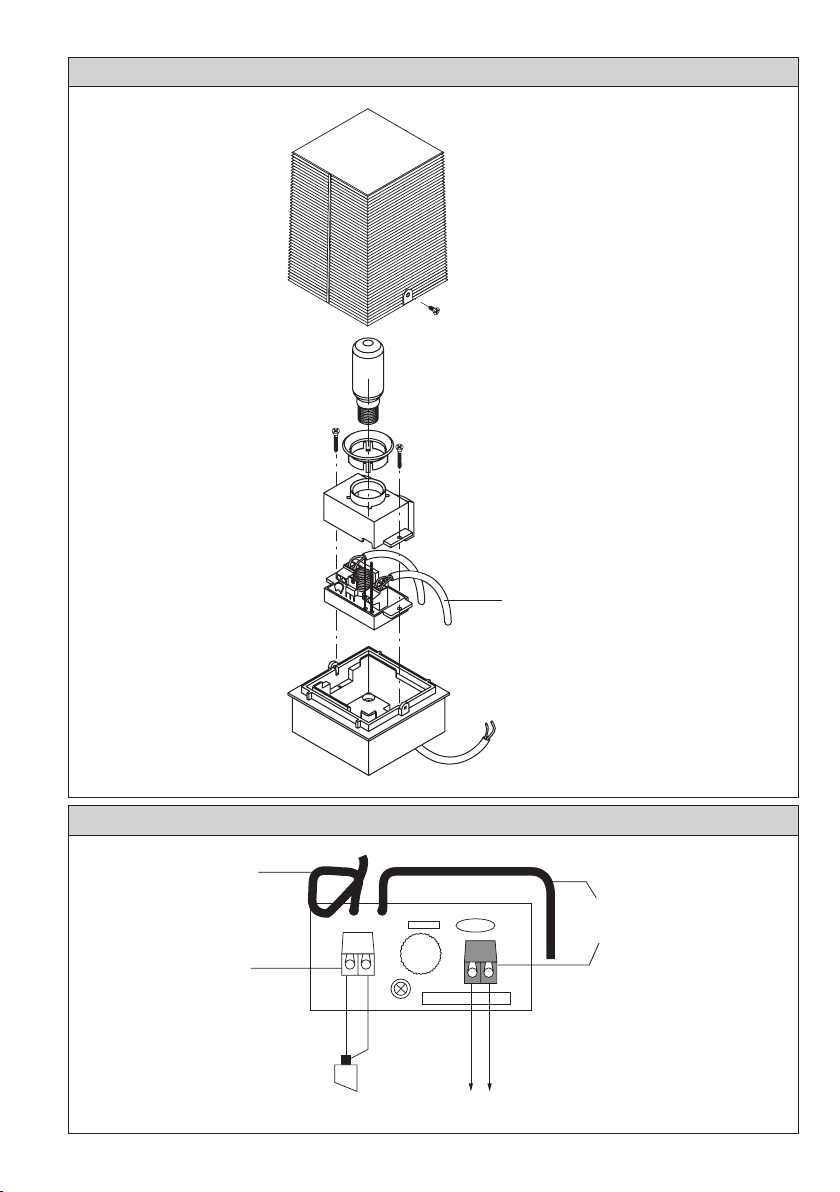
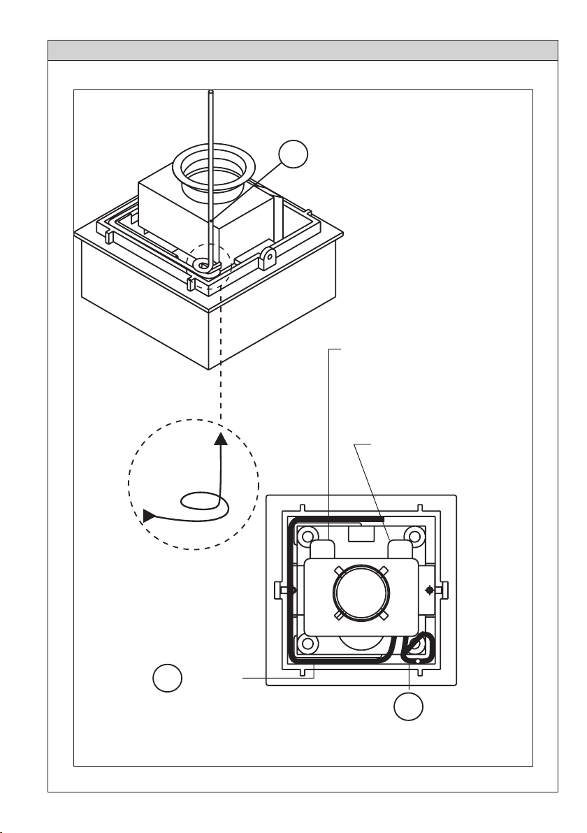
c) Il cavo giallo (A) dev’essere avvolto a spirale e il cavo nero (B) deve seguire il percorso indicato (Fig.3).
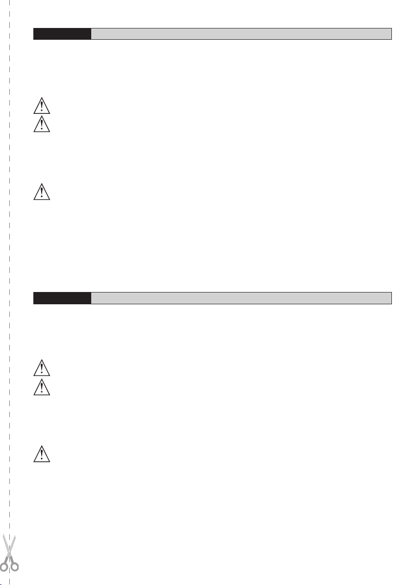
3) ASSEMBLAGGIO
Assemblare le parti come indicato in fig.1.
3.1) COLLEGAMENTO MORSETTIERA (Fig. 1A)
JP1 Alimentazione (LINE) Connettore nero.
JP2 Ingresso antenna (ANT) Connettore bianco.
ATTENZIONE! Per il collegamento alla rete, utilizzare cavo multipolare di sezione minima 2x1.5mm2 tipo
H05 VV-F protetto in canaletta.
4) CARATTERISTICHE TECNICHE
MOD. ALIMENTAZIONE LAMPADA PREDISPOSTO ANTENNA
LAMPO AI 230Vac (*) E14 230V/40W SI
LAMPO AI 24 24Vac-dc E14 24V/25W SI
(*) Disponibili anche a 110V
Frequenza: 433.92MHz
5) MANUTENZIONE
PERICOLO! Togliere l’alimentazione dell’automazione per qualsiasi intervento di manutenzione o riparazione.
Pulire periodicamente la calotta del lampeggiante.
1) GENERAL OUTLINE
Visual safety blinker, suitable for signalling the movement of an automated gate or door.
The blinker can only be used with the control units supplied by the manufacturer.
2) FITTING
a) Direct vertical fitting (fig. 1).
b) Wall vertical fitting (fig. 2) with SLM2 mod. support (accessory) In case of vertical positioning, the degree of protection is IP44.
WARNING! The presence of metallic masses next to the antenna can interfere with radio reception.
c) The yellow cable (A) must be wound up to form a spiral and the black cable (B) must follow the indicated path (Fig.3).
3) ASSEMBLY
Assemble the components as shown in fig. 1.
3.1) TERMINAL BOARD CONNECTIONS (Fig. 1A)
JP1 Power supply (LINE) Black connector.
JP2 Antenna input (ANT) White connector.
WARNING! To effect the connection to the mains, use a multipolar cable with a minimum section of 2x1.5mm2
type H05 VV-F protected by a raceway.
4) TECHNICAL SPECIFICATIONS
MOD. POWER SUPPLY BULB PRESET FOR ANTENNA
LAMPO AI 230Vac (*) E14 230V/40W YES
LAMPO AI 24 24Vac-dc E14 24V/25W YES
(*)Also available at 110V
Frequency: 433.92MHz
5) MAINTENANCE
DANGER! Before any maintenance or repair operation, disconnect the automation system from the power supply.
Periodically clean the blinker hood.