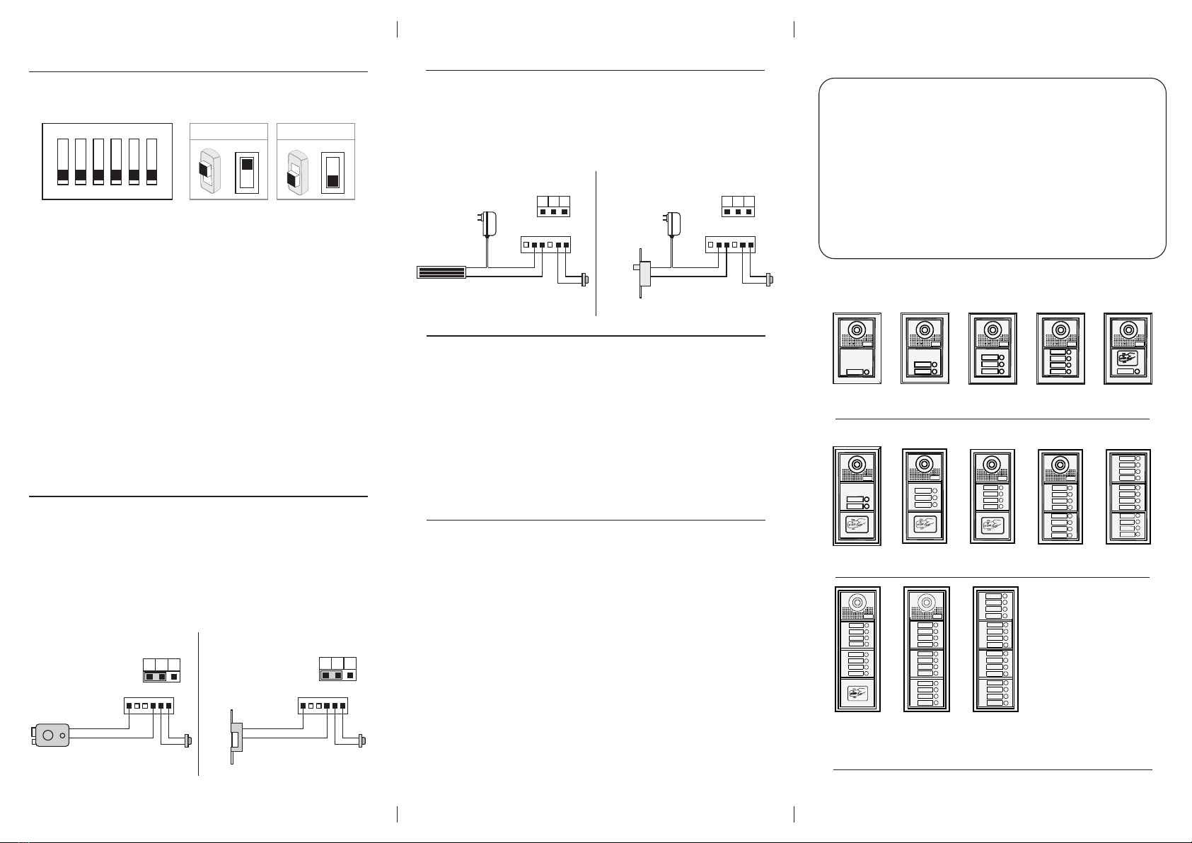
Door Station
2-wire Door Station
Quick Installation Guide
Please read this manual carefully before using the product .
010101
030303
040404
020202
010101
030303
020202
010101
020202
010101
010101
02
01
17
18
20
19
23
24
22
21
15
16
14
13
11
12
10
09
05
06
08
07
03
04
02
01
07
08
06
05
01
02
04
03
27
28
26
25
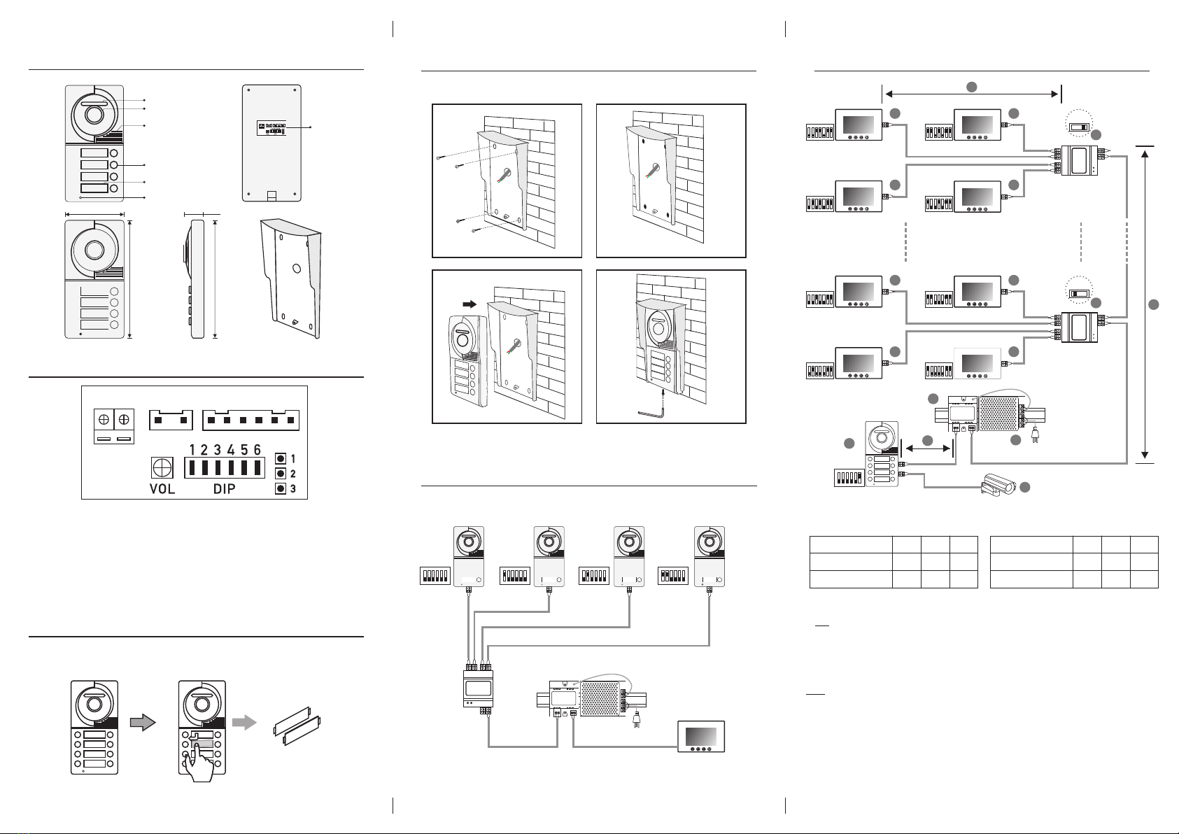
Dimension: 195(H)×130(W)×52(D)mm
Embedded Dimension: 185(H)×110(W)×33(D)mm
Dimension: 276(H)×130(W)×52(D)mm
Embedded Dimension: 270(H)×108(W)×33(D)mm
Dimension: 360(H)×130(W)×52(D)mm
Embedded Dimension: 350(H)×110(W)×33(D)mm
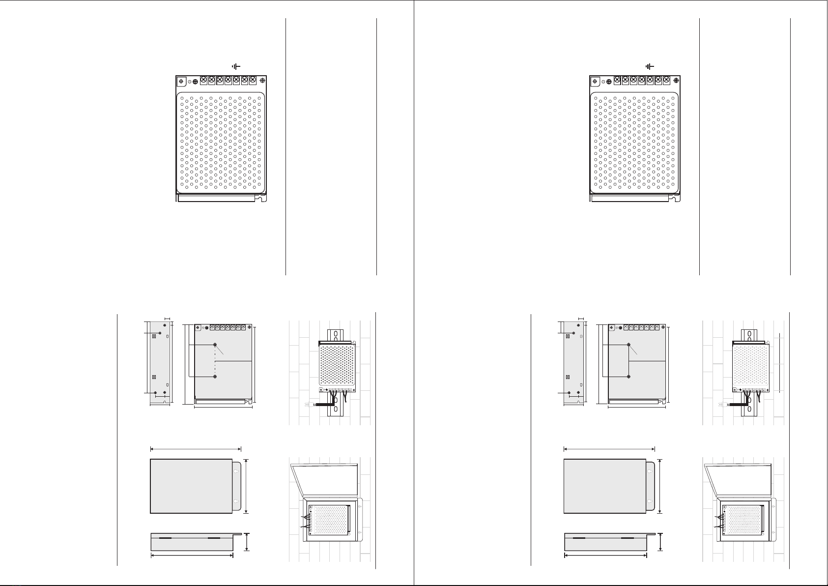
9. Specification
ŸPower supply: DC 24V
ŸPower Consumption: 1W in standby, 5W in working
ŸUnlock Power output: 12Vdc, 250mA
ŸUnlock timing: 1s, 5s, 10s, 15s
ŸWorking Temperature: -20℃~ +55℃
-5-
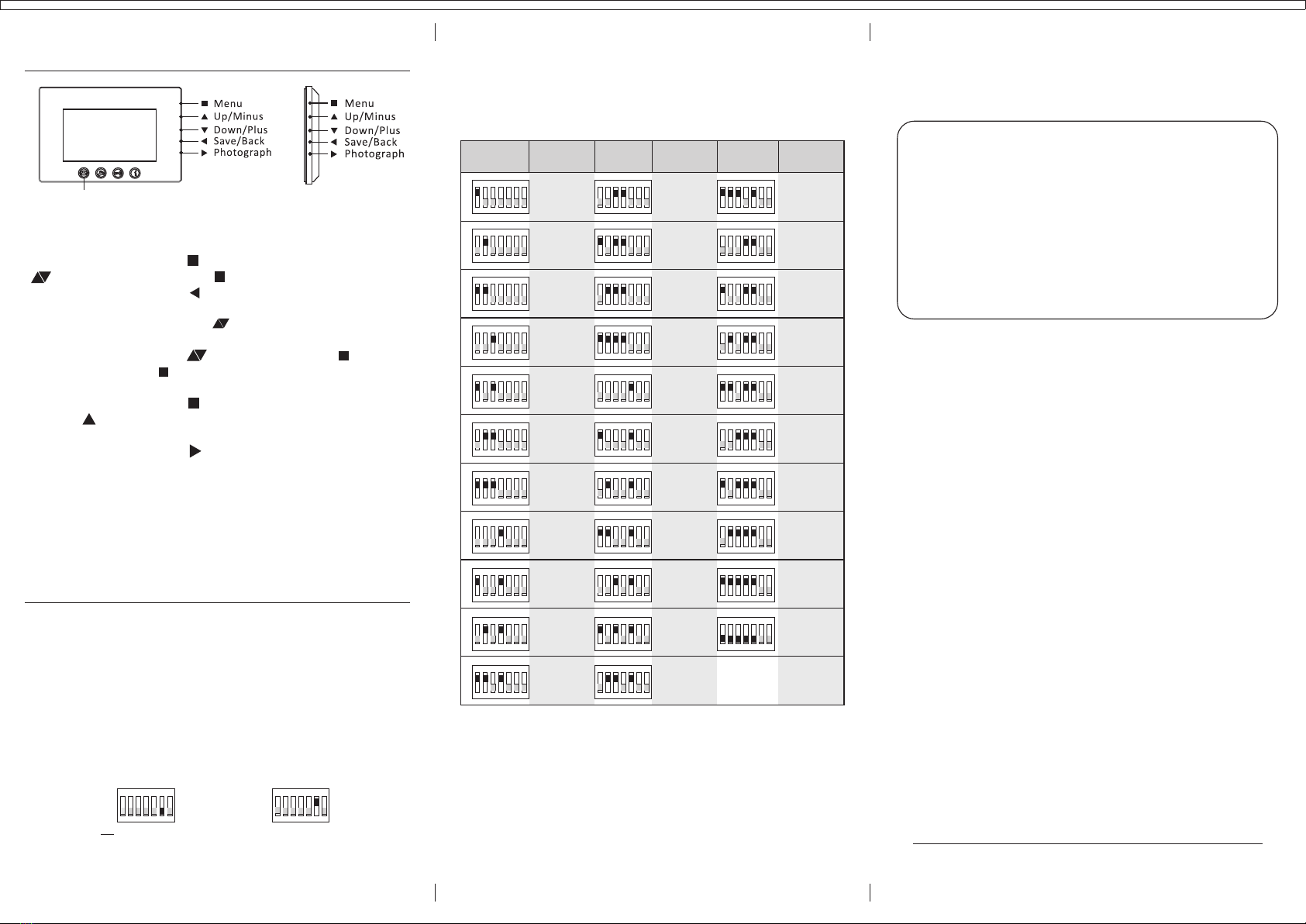
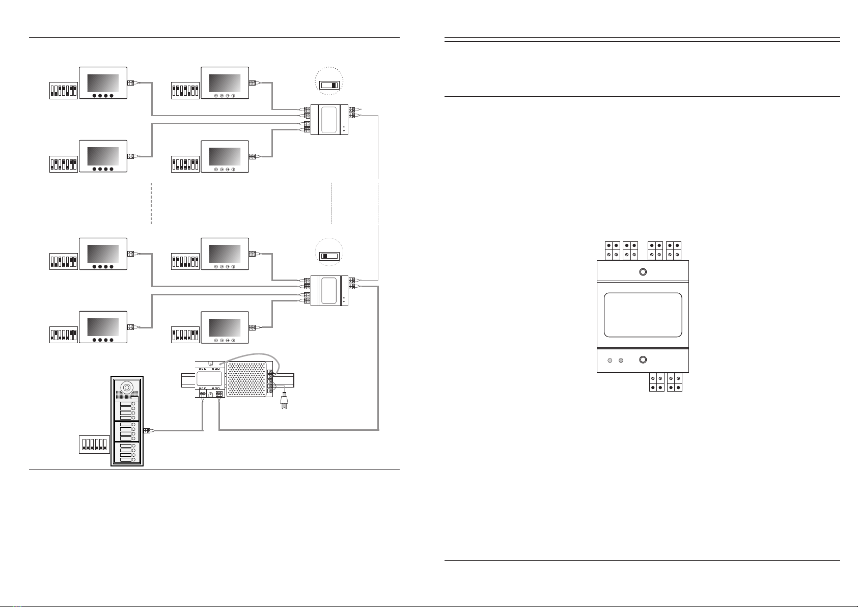
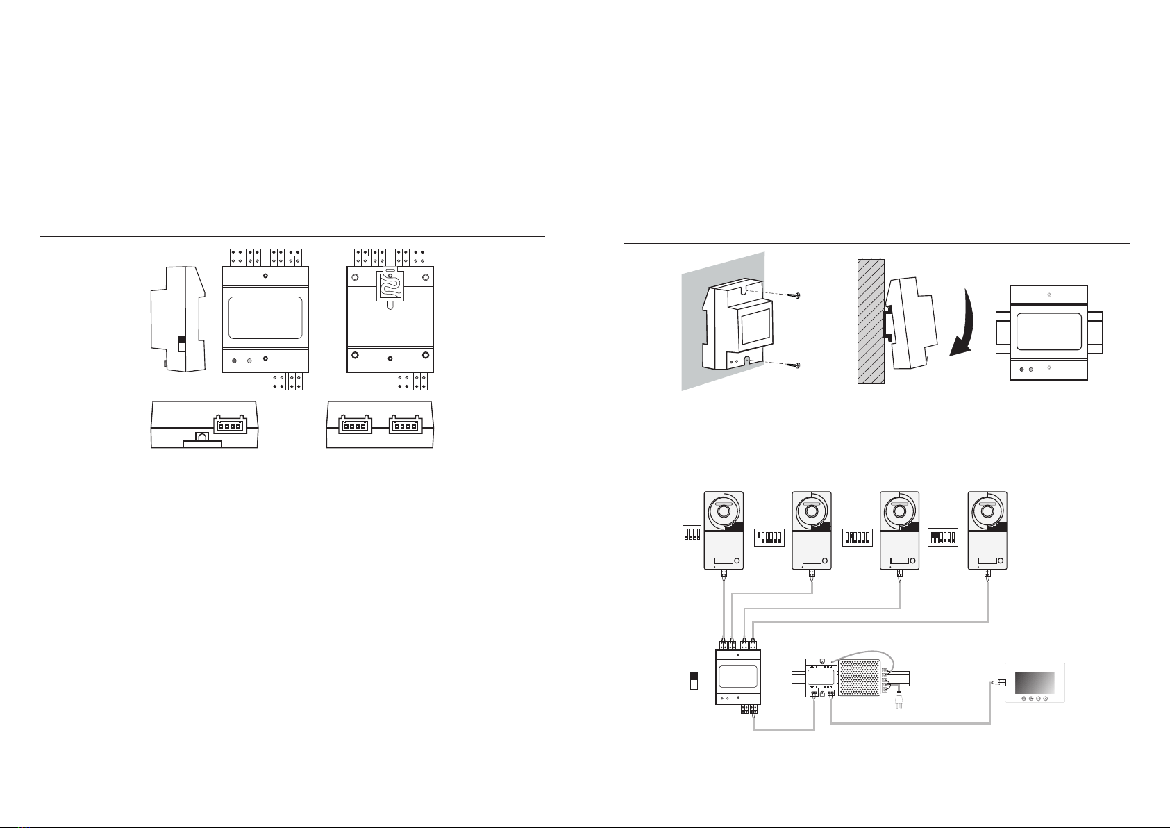
6. DIP Switches Settings
Total 6 bits in the DIP switches can be configured. The switches can be modified either
before or after installation.
1 2 3 4 5 6
ON DIP
ON
ON
ON (1) OFF (0)
= =
Bit-1,Bit-2 and Bit-3 are used for door station ID setting(1=on,0=off).Bit-1,Bit-2 and Bit-3 are used for door station ID setting(1=on,0=off). Bit-1,Bit-2 and Bit-3 are used for door station ID setting(1=on,0=off).
000 - 100 - 010 - 110 - 001 - 101 - 011 - 111
000 - First door station
100 - Second door station
010 - Third door station
110 - Fourth door station
If there's extra camera connected with the system. The door station ID would be
000 - First door station
010 - Second door station
001 - Third door station
011 - Fourth door station
Bit-4 and Bit-5 is used for unlock time setting.
00 - 1 second (Default setting)
10 - 5 seconds
01 - 10 seconds
11 - 15 seconds
Bit-6 is used for connecting extra camera.
0 - No extra camera (Default setting)
1 - Connecting with extra camera
-4-
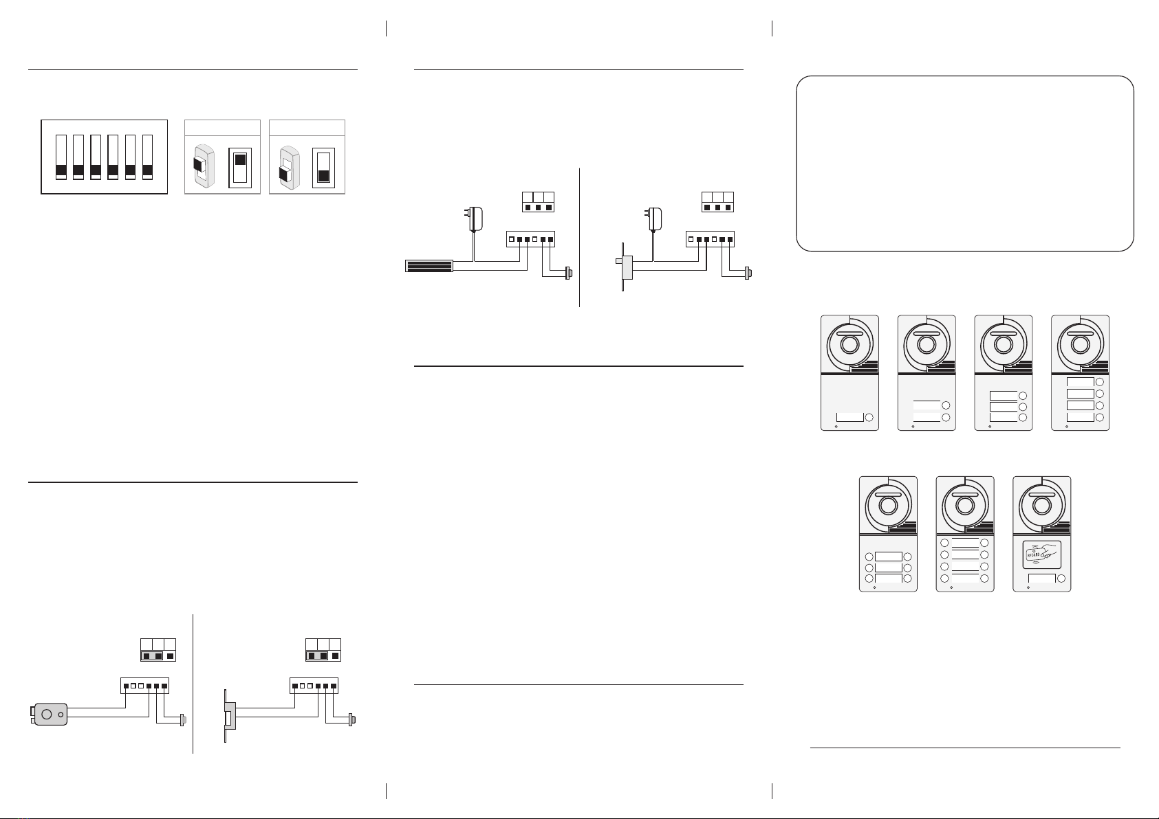
7. Electric Lock Connection
12V 300mA
+
-
Jumper position in 2-3
NO NC COM GND GND OPEN
CN3
Exit button
12V 300mA
+
-
Jumper position in 1-2
NO NC COM GND GND OPEN
CN3
Exit button
*Revision: PL161226
Power ON to open Power on to unlock type
1. The door lock power for a 12v DC strike (max current=250mA).
2. Set the jumper SIP1 set to 1-2 for a normally closed lock (power OFF to open), or set SIP1
to 2-3 for a normally open lock(power ON to open.
3. Adjust the timer setting with Bit-4 and Bit-5 at the outdoor station
(1=on,0=off)
00-1sec, 01-5sec,10-10sec,11-15sec
8. Electric Lock Connection
1. The external power supply must be used according to the lock.
2. The jumper must be taken off before connecting.
3. If different unlocking time is needed, change the unlock time on door station by
modifying the BIT-4 and BIT-5.
+
-
Take off the jumper
NO NC COM GND GND OPEN
CN3
1 2 3
SIP1
Exit button
-
+
+
-
Take off the jumper
NO NC COM GND GND OPEN
CN3
1 2 3
SIP1
Exit button
-
+
Power off to unlock type Power off to unlock type
1 2 3
SIP1
1 2 3
SIP1
01
02
04
03
07
08
06
05
03
02
01
09
10
12
11
15
16
14
13
19
20
18
17
03
04
02
01
1) : Make a master card
Firstly to cut off the power of the outdoor station, secondly to connect JP2 with power, then
sound will be heard every 1.5second,now to swipe new ID card will hear a long beep, that means
new master card has been made,finally to take off JP2 will exit.
2) : Delete all user cards
Firstly to cut off the power of the outdoor station, then to connect JP3 with power,now a long
beep will be heard, that means all user cards has been deleted, finally to take off JP3 will exit.
3) :Add more user ID card
Under standby,firstly to swipe the Master card, then to swipe new User cards one by one, now
to swipe the Master card again, so new User cards have been made. only 2720pcs user cards can
be made in the system.
4) :Open the door by ID user card
Under standby, to swipe the active access ID user card on the access window will open the door,
if the User card is not activated by the Master card, then the door can not be open and Dee beep
will be heard at 3 times.
10.User Instructions of RFID Access Control