Framery O User manual

Framery O
Installation instructions English
Version 2.0


Contents
1 Warranty checklist....................................................................................... 5
2 Important safety and product instructions............................................... 6
2.1 Preface....................................................................................................................6
2.2 Product information................................................................................................ 6
2.3 Copyright.................................................................................................................6
2.4 Manual contents..................................................................................................... 6
2.5 Intended use...........................................................................................................6
2.5.1 Non-conventional use.................................................................................6
2.5.2 Ambient conditions for use.........................................................................7
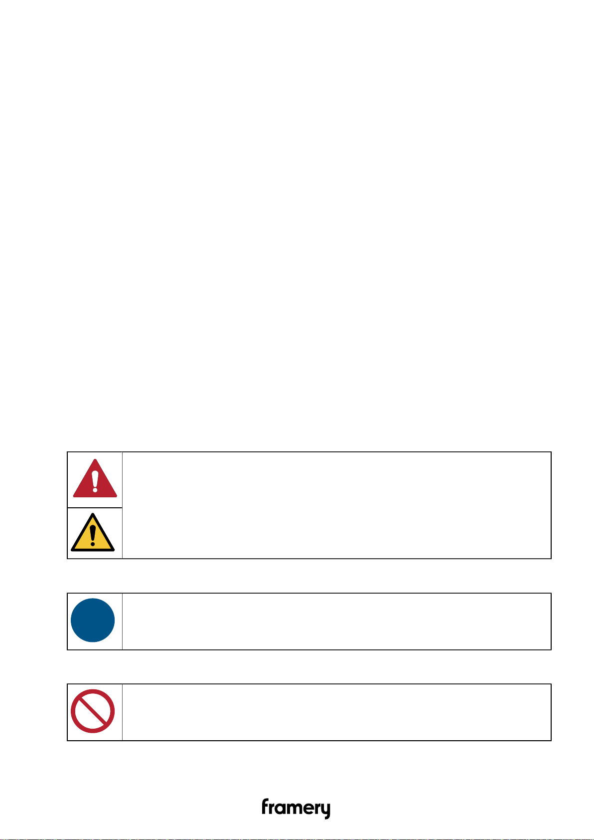
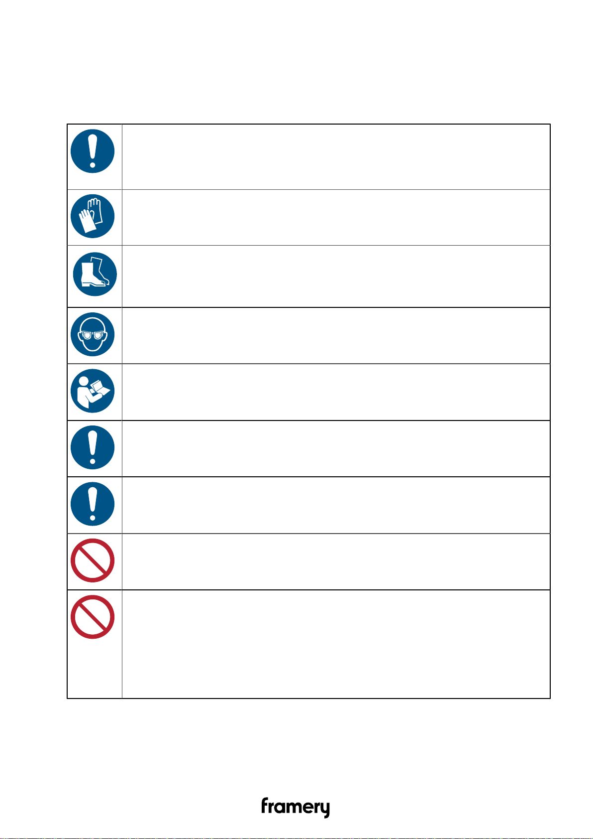
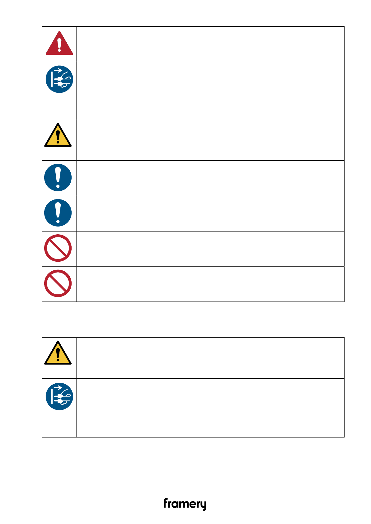
2.6 Warning, information and safety symbols in this manual....................................... 7
2.7 Main safety risks related to the installation, maintenance, disassembly and use
of the product........................................................................................................... 8
2.7.1 Installation, maintenance and disassembly................................................8
2.7.2 Electrical safety.......................................................................................... 8
2.7.3 Fire safety...................................................................................................9
2.7.4 Use............................................................................................................10
2.8 Location of Product Markings...............................................................................11
3 Installation requirements.......................................................................... 17
3.1 Tools and accessories.......................................................................................... 17
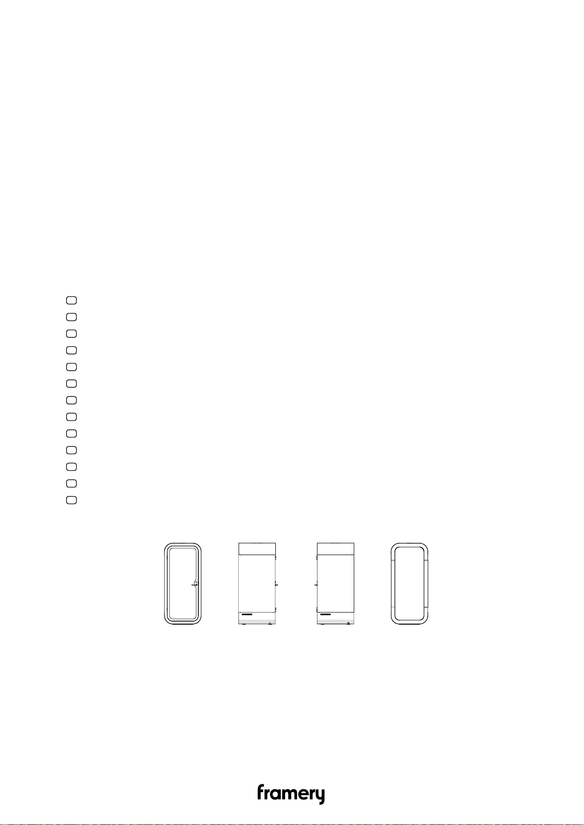
3.2 Main dimensions...................................................................................................18
3.3 Installation space..................................................................................................18
3.4 Operating space................................................................................................... 19
4 Level the floor module..............................................................................20
5 Install the wall modules............................................................................22
5.1 Remove the wall cover panels.............................................................................22
5.2 Connect the wall modules to the floor module.....................................................24
6 Connect the roof module to the wall modules....................................... 28
7 Remove the roof cover panels.................................................................30
8 Check the straightness of the pod.......................................................... 31
9 Install the table and electrics................................................................... 34
9.1 Check the serial number...................................................................................... 34
9.2 Mount the table to the wall.................................................................................. 35
9.3 Install the electrical connections.......................................................................... 36

10 Install the door.........................................................................................43
10.1 Install the door with frames................................................................................43
10.2 Install the door handle........................................................................................47
10.3 Program the master code into the code handle (optional)................................. 50
10.4 Install the code handle (optional)....................................................................... 51
11 Install the glass wall................................................................................53
11.1 Install the floor cover panels.............................................................................. 55
12 Install the interior.................................................................................... 57
12.1 Install the stool and carpet.................................................................................57
12.2 Install the carpet (no stool)................................................................................ 59
13 Install the power cord from the floor.................................................... 61
14 Install the power cord from the roof..................................................... 62
15 Install the cover panels and body covers.............................................63
15.1 Install the wall cover panels...............................................................................63
15.2 Install the roof cover panels...............................................................................64
15.3 Install the bottom body covers........................................................................... 65
15.4 Install the roof body covers................................................................................68
15.5 Install the wall body covers................................................................................71
16 Perform final checks............................................................................... 73
16.1 Check the door alignment.................................................................................. 73
16.2 Adjust the door height........................................................................................ 73
16.3 Finish the installation..........................................................................................77

1 Warranty checklist
For the product warranty to be valid:
Fill this checklist and send it to Framery after pod installation. Take a photo or scan the filled list and send it to Framery at
[email protected]. Leave the completed list on the pod's glass door.
Country: _________________________________________
City: _________________________________________
Customer: _________________________________________
Pod serial number: _________________________________________
SO number: _________________________________________
Installation company: _________________________________________
Name of technician: _________________________________________
YES
All bolts are tightened according to the instructions
The pod is leveled and standing on the feet of the leveling screws
When the door is left open, it is either at standstill or closes
The door height is adjusted to the middle of the opening
The door handle is not loose and is installed according to instructions
The pod power cord is connected according to the instructions
The light and fans switch on when a person enters the pod
The fans are making a quiet and even sound
Air flows into the pod from the ventilation channels in the roof module
All of the furniture is installed securely and according to the instructions
Air flows out of the pod's ventilation channels when the door is closed
The body covers are installed according to the instructions
The light inside the pod switches off after approximately 8 minutes of no activity
Circle the location of scratches or any other visual defects below. Attach pictures and descriptions of the defects
to the warranty email.
I certify that the pod is installed according to Framery installation instructions and the pod has been checked to be
operating correctly.
Signature and date: ___________________________________________________________
Framery O Installation instructions
5

2 Important safety and product instructions
2.1 Preface
This instruction manual describes the installation of the product. Everyone involved in
installing the product must read and understand the contents of the installation and safety
instructions.
This instruction manual gives you necessary information for the correct installation of the
product.
2.2 Product information
The information in this manual corresponds to the product at the time of delivery. All
information included in this manual is valid at the time of publication.
2.3 Copyright
This document must not be copied, presented, or delivered to a third party without explicit
permission from Framery. The use of this document for any purpose other than those
allowed by Framery is prohibited. Framery reserves the right to change the instructions
related to the product without separate notice.
2.4 Manual contents
The installation instructions contain the following information:
• General information about the purpose and content of the instructions
• Information related to safety
• Installation instructions
2.5 Intended use
The Framery OO VCR is a pod intended for short term indoor commercial and household
use by one (1) person at a time.
Warning: WARNING –To reduce the risk of burns, fire, electric shock, or injury to
persons:
Use this product only for its intended use as described in the user instructions. Do not use
attachments not recommended by the manufacturer.
2.5.1 Non-conventional use
Any use or maintenance of the product that is not specifically allowed in the installation,
maintenance, troubleshooting or user instructions is prohibited, including the following:
• Installation, maintenance or disassembly of the pod without reading and understanding
the instructions for those actions
• Use of the pod beyond the limits of use
6Framery O Installation instructions

• Making alterations to the pod
• Using the pod in spite of obvious defects or damage
• Using the pod outdoors or in conditions where the temperature or air quality is not safe
• Climbing on top of the product or placing any load on the roof of the product
• Smoking in the pod
2.5.2 Ambient conditions for use
The pod is intended to be used in the following conditions:
• Ambient temperature: +15°C ... +30°C (59°F ... 86°F)
• Humidity: max. 50%
• Sufficient air quality surrounding the product
2.6 Warning, information and safety symbols in this manual
The warnings in this manual have been divided into the following two categories:
• The term "DANGER" indicates a hazardous situation which, if not avoided, will result in
death or serious injury.
• The term “WARNING” indicates a hazardous situation which, if not avoided, could result
in death or injury.
The safety symbols found in this manual may also be posted on the product. All personnel
who install, disassemble, perform maintenance or use the product are to be familiar
with and observe all safety symbols, labels, and instructions about the action they are
performing.
Table 1: Hazard
An exclamation point symbol inside a colored triangle indicates a hazardous
situation.
Table 2: Mandatory action
A white symbol inside a colored circle indicates an action that must be taken to
avoid a hazardous situation.
Table 3: Prohibited action
A ring with a diagonal bar indicates an action that is not allowed.
Framery O Installation instructions
7

2.7 Main safety risks related to the installation, maintenance, disassembly
and use of the product
2.7.1 Installation, maintenance and disassembly
WARNING!
To reduce the risk of burns, fire, electric shock, or injury to persons, obey
the following:
Use cut resistant safety gloves during the installation, maintenance or
disassembly of the product.
Use steel toed safety boots during the installation, maintenance or disassembly
of the product.
Use safety glasses during the installation, maintenance or disassembly of the
product.
Read and understand the instructions and plan your work beforehand.
Obey all local rules and regulations regarding workplace safety.
Keep the work site tidy and free from debris throughout the installation,
maintenance or disassembly process.
Do not climb on top of the product or place any load on the roof of the product.
Do not push the product to move it if not specifically instructed to do so in this
manual.
The product is very heavy and moving the product after installation requires a
significant amount of force. Moving a finished product without disassembly and
reassembly requires an on-site risk assessment to be performed by the party
responsible for moving the product.
2.7.2 Electrical safety
Input for the electrical system: 100-240 VAC (10 A) 50-60 Hz
The maximum load for the electrical system is 6.6 A.
8Framery O Installation instructions

DANGER!
To reduce the risk electric shock, obey the following:
Disconnect the power cord from the power outlet before starting any cleaning,
maintenance or disassembly procedures.
The power cord serves as a power disconnect device for pluggable equipment.
The power outlet shall be located near the equipment and shall be easily
accessible.
WARNING!
To reduce the risk of burns, fire, electric shock, or injury to persons, obey
the following:
Connect the power cord to a properly grounded outlet only.
Keep the power cord of the product away from heated surfaces.
Do not use the pod if you notice any defects or damage to the electrical
equipment.
Do not connect any extension cords to the power outlet(s) of the product.
2.7.3 Fire safety
The fire load for the Framery OO VCR is approx. 3200 MJ.
WARNING!
To reduce the risk of burns, fire, electric shock, or injury to persons, obey
the following:
If safely possible to perform, disconnect the power cord from the power outlet if
there is a fire inside the product.
The power cord serves as a power disconnect device for pluggable equipment.
The power outlet shall be located near the equipment and shall be easily
accessible.
Fire safety end devices (alarms, sprinklers etc.) can also be installed inside the pods
(instructions available upon request). The need for end devices inside the pod is always
determined by the applicable local authorities.
Framery O Installation instructions
9

2.7.4 Use
Maximum load for the table is 139 lbs (63 kg).
Maximum load for the Tovi Stool is 300 lbs (136 kg).
Maximum load for the display bracket is 22 lbs (10 kg).
WARNING!
To reduce the risk of burns, fire, electric shock, or injury to persons, obey
the following:
Read and understand the user instructions before using the product.
Close supervision is necessary when this furnishing is used by, or near
children, invalids, or disabled persons.
Keep children away from extended foot support (or other similar parts).
Do not use the product if the surrounding conditions are in any way hazardous;
the air circulating inside the pod is derived from the surrounding space.
Do not use the product if the ventilation is not functioning.
Do not use the product if the ventilation channels are blocked. Keep the
ventilation channels free of lint, hair, and the like.
Do not use the pod if you notice any defects in the electrical equipment or if
the product is not working properly. Disconnect the power cord from the power
outlet and contact your local dealer or the manufacturer immediately.
Do not drop or insert any object into any opening if not specifically instructed to
do so in this manual.
Do not use outdoors.
Do not use where aerosol (spray) products are being used or where oxygen is
being administered.
10 Framery O Installation instructions

Do not climb on top of the product or place any load on the roof of the product.
Do not lean against the product.
Do not smoke inside the product.
2.8 Location of Product Markings
Framery O Installation instructions
11

Position Label Label text
1. Framery
This furnishing has not been evaluated for
flammability or cigarette ignition resistance
L'inflammabilité ou la résistance à l'allumage d'une
cigarette n'a pas été évaluée pour cette garniture
12 Framery O Installation instructions

Position Label Label text
2. Framery
PRODUCT NO. / N° DE PRODUIT
Product / Produit FRAMERY O FRAMERY O VCR
Input / Entrée 100-240VAC 10A 50-60HZ
Manufacturer / Fabricant: Framery Oy
WEB: www.frameryacoustics.com Email:
[email protected] Made in Finland/
Fabriqué en Finlande
Attention! Always connect the product correctly
to a grounded socket to avoid danger for fire or
electrical shocks.
Product evaluated class A (ASTM E84 / UL 723)
Attention! Branchez toujours le produit dans
une prise reliée à la terre pour éviter tout risque
d’incendie ou de choc électrique.
Produit de classe A (ASTM E84 / UL 723)
3. SN / N° de série:
MANUFACTURE DATE / DATE DE FABRICATION:
[month] - [year]
4. Framery
WARNING - Risk of fire and shock Use only ‘SJT’
type ‘16’ AWG cord
AVERTISSEMENT - Risque d’incendie et de
choc électrique, utiliser uniquement un cordon
d'alimentation ‘SJT’ de type ‘16’ AWG
Framery O Installation instructions
13

Position Label Label text
5. Framery
WARNING Risk of injury Maximum table load 139
lbs / 63 kg
L'AVERTISSEMENT Risque de blessure Poids
maximal autorisé 139 lbs / 63 kg
Position Label Label text
1. Framery
This furnishing has not been evaluated for
flammability or cigarette ignition resistance
L'inflammabilité ou la résistance à l'allumage d'une
cigarette n'a pas été évaluée pour cette garniture
14 Framery O Installation instructions

Position Label Label text
2. Framery
PRODUCT NO. / N° DE PRODUIT
Product / Produit FRAMERY O FRAMERY O VCR
Input / Entrée 100-240VAC 10 A 50-60HZ
Manufacturer / Fabricant: Framery Oy
WEB: www.frameryacoustics.com Email:
[email protected] Made in Finland/
Fabriqué en Finlande
Attention! Always connect the product correctly
to a grounded socket to avoid danger for fire or
electrical shocks.
Product evaluated class A (ASTM E84 / UL 723)
Attention! Branchez toujours le produit dans
une prise reliée à la terre pour éviter tout risque
d’incendie ou de choc électrique.
Produit de classe A (ASTM E84 / UL 723)
3. SN / N° de série:
MANUFACTURE DATE / DATE DE FABRICATION:
[month] - [year]
4. Framery
WARNING - Risk of fire and shock Use only ‘SJT’
type ‘16’ AWG cord
AVERTISSEMENT - Risque d’incendie et de
choc électrique, utiliser uniquement un cordon
d'alimentation ‘SJT’ de type ‘16’ AWG
Framery O Installation instructions
15

Position Label Label text
5. Framery
WARNING Risk of injury Maximum table load 139
lbs / 63 kg
L'AVERTISSEMENT Risque de blessure Poids
maximal autorisé 139 lbs / 63 kg
6. Framery
WARNING Risk of injury Maximum load 22 lbs / 10
kg
L'AVERTISSEMENT Risque de blessure Poids
maximal autorisé 22 lbs / 10 kg
SAVE THESE INSTRUCTIONS
16 Framery O Installation instructions

3 Installation requirements
3.1 Tools and accessories
Figure 1: Tools and accessories needed for installation and maintenance
Note: Use a white rubber mallet to prevent marks on the body covers.
Note: Use a plastic chisel to remove the body covers.
Note: Use a lint-free cloth to clean the pod.
Framery O Installation instructions
17

Note: Use a mild alcohol-based cleaning solution to clean the pod.
3.2 Main dimensions
Figure 2: Main dimensions
3.3 Installation space
Make sure that you have enough installation space before you start the installation.
Figure 3: Installation space measures
Figure 4: Installation space measures
18 Framery O Installation instructions

3.4 Operating space
Make sure that the pod has enough space for the air to circulate correctly.
Figure 5: Operating space measurements
Figure 6: Operating space measurements
Figure 7: Operating space measurements
Framery O Installation instructions
19

4 Level the floor module
1. Lay the floor module down at the intended final location.
Leave approximately 0.5 m (2 ft) of empty space behind the floor module.
Note: The stool mounting notch is closer to the backside of the pod.
2. Screw out the feet of the leveling screws (4 pcs) gradually with a T-handle socket
wrench.
The feet of the leveling screws are against the floor when you feel resistance.
20 Framery O Installation instructions
Other manuals for O
4
Table of contents