France Air MODULYS Eco 500 User manual

_______________________________________________________________ NT 1900 B – 01/20191
BEFORE STARTING ANY INSTALLATION, MAINTENANCE OR DISASSEMBLY PROCEDURES, PLEASE READ
THIS MANUAL VERY CAREFULLY. THE MANUFACTURER CANNOT BE HELD LIABLE FOR ANY PHYSICAL
INJURY AND/OR DAMAGE TO PROPERTY RESULTING FROM FAILURE TO FOLLOW THE INSTRUCTIONS
GIVEN IN THIS MANUAL.
TECHNICAL MANUAL
MODULYS® Eco
Economical modular ventilation unit

NT 1900 B – 02/2019 _______________________________________________________________2
1GENERAL INFORMATION
1.1 BEFORE YOU START
Before installation, please read this manual, which contains all the instructions on using the product
correctly and safely.
This manual contains important instructions to ensure correct installation of the ventilation unit.
Before installing the unit, please carefully read and follow all the instructions below. The manufacturer
reserves the right to make changes to this manual and to the technical documentation without prior
notice. Please keep this manual for future use. Please consider this manual as an integral part of the
product.
Installation and maintenance must only be carried out by qualified and experienced technicians to
ensure compliance with the local standards in force and to maintain the warranty.
1.2 RECEIPT OF THE PRODUCT
Upon delivery, immediately check whether the product packaging is intact. In case of damage to the
package, inform the haulier. If the complaint is not made on time, a subsequent application will no
longer be accepted. Check that the type of product delivered corresponds to your order. If in doubt,
do not unpack the unit, and inform France AIR.
After unpacking, check the condition of the units and all components. If in doubt, consult the supplier.
Never use a damaged unit. Always store in a dry location with an ambient temperature of between +5
°C and +35 °C.
If these instructions are not followed, the France AIR warranty will be invalid.
If the ventilation unit has been exposed to temperatures of less than 0 °C during transport, leave the
unit unpacked at ambient temperature for at least 2 hours before commencing system start-up, to
allow the temperature in the unit to equalise.
In general, avoid storing the product for long periods; if this cannot be avoided, a full inspection must
be performed before start-up, paying particular attention to the turbine bearings. A maximum storage
period of 1 year is recommended.
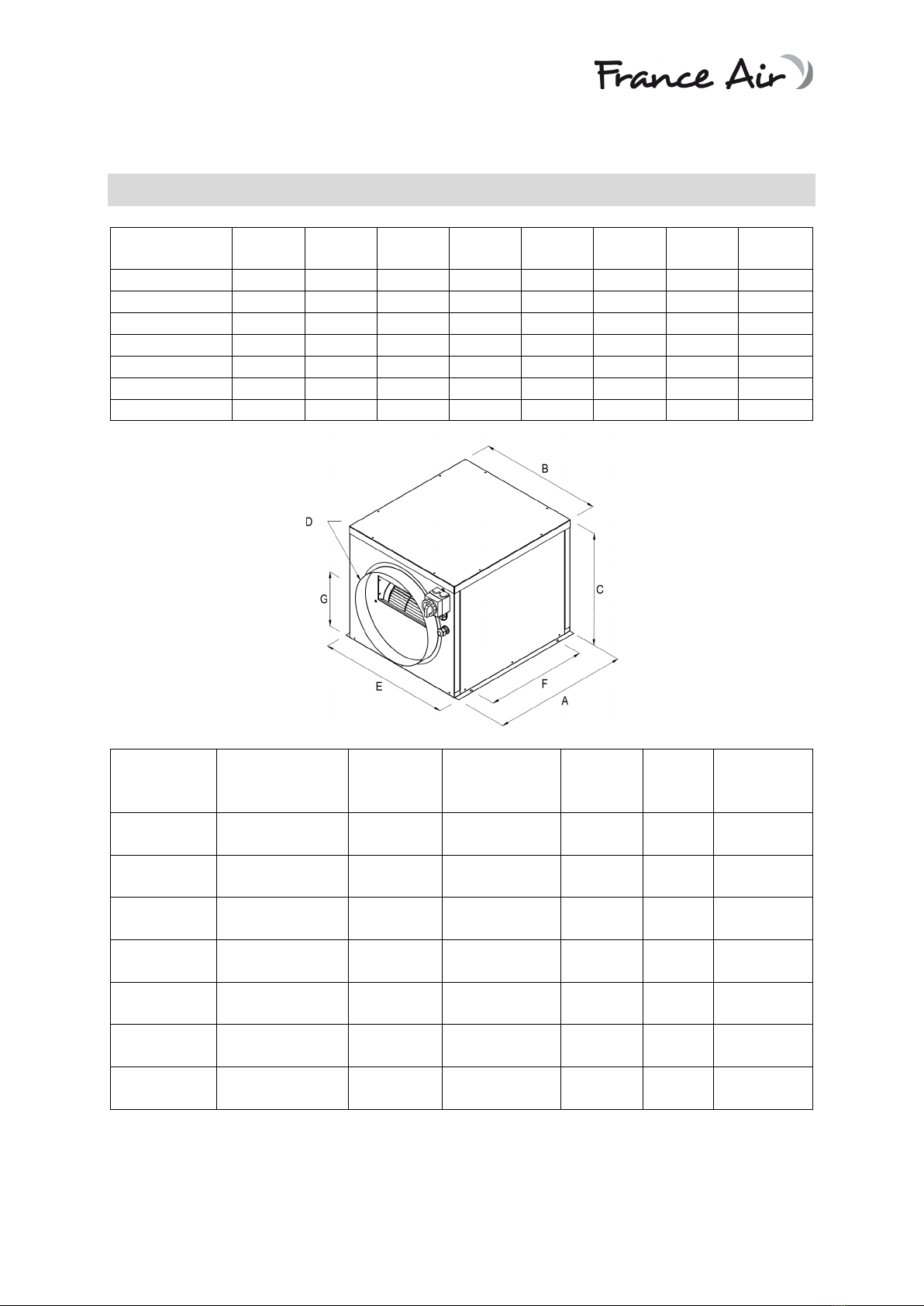
1.3 PRODUCT DESCRIPTION
The MODULYS® Eco unit is a fan unit designed to be integrated into single-flow ventilation installations,
for air supply or extraction, and is intended for use in tertiary buildings.
MODULYS® Eco fans are centrifugal fans with backward-curved blades (size 500) and with forward-
curved blades (size 800 and above), directly coupled to an asynchronous motor.
The product is equipped with a single filter on the intake
2SAFETY INFORMATION
The MODULYS® Eco unit is designed to convey clean air, i.e. it must not be used for extraction or supply
of smoke, gas, or dust. Similarly, it should not be used in an explosive or corrosive atmosphere.
To ensure the MODULYS® Eco provides a maximum service life, if used in a harsh environment, the
MODULYS® Eco ventilation unit should be run permanently.
The MODULYS® Eco can be used outdoors. However, you must check that the unit is installed on
drained ground or a raised support.
It can be installed in any position.

NT 1900 B – 02/2019 _______________________________________________________________3
The MODULYS® Eco must be powered according to the electrical specifications (voltage and frequency)
indicated on the label affixed on the outside of the unit.
3SPECIFICATIONS
MODULYS® Eco UNIT DIMENSIONS
MODULYS®
Eco
A (mm)
B (mm)
C (mm)
D (mm)
E (mm)
F (mm)
G (mm)
Weight
(kg)
500
497
442
460
250
461
350
239
15
800
567
513
470
355
531
420
230
19
1200
567
513
515
355
531
420
242
21
2500
677
623
555
400
640
530
307
35
3500
737
683
650
450
700
590
346
42
4200
737
683
650
500
700
590
346
43
5000
810
754
735
630
769
662
365
50
TECHNICAL DESCRIPTION
MODULYS®
Eco Power supply Power (W) Nominal
current (A)
Speed
(rpm)
Max.
fluid T°
(°C)
Motor
protection
rating
500
Single-phase
230 V
122 0.5 2800 40 44
800
Single-phase
230 V
300 1.4 2548 40 44
1200
Single-phase
230 V
147 1.2 1346 40 44
2500
Single-phase
230 V
245 2.2 947 40 55
3500
Single-phase
230 V
245 2.8 949 40 55
4200
Three-phase
400 V
350 1.7 949 40 55
5000
Three-phase
400 V
550 2.9 949 40 55
The MODULYS® Eco unit is designed to operate in an ambient temperature range of -20 °C to 40 °C.

NT 1900 B – 02/2019 _______________________________________________________________4
4INSTALLATION
4.1 HANDLING AND MOUNTING THE PRODUCT
The unit must be installed so as to enable access for maintenance, service or removal operations. This
mainly means access to the removable panels, the electrical connections and to the panel equipped
with the fan unit.
All the materials used at a distance of less than 100 mm from the ventilation unit must be non-
flammable (must be non-combustible; must not burn or ignite) or fire resistant (must be consumed
without burning - for example, plasterboard).
These materials may not, however, cover the air intake and supply air openings. The safety distance
between the supply air outlets and flammable materials is 500 mm. The safety distance in the other
directions is 100 mm for flammable materials.
Drill the holes in the support, ensuring that the structure is of solid construction, and attach the unit
to the support battens designed to house the unit using M8 threaded rods.
Attention!
The mounting must be able to withstand the weight of the unit. Given the weight of the unit, it is
necessary to use either suitable handling equipment to lift it (forklift or similar), or to enlist the help
of two other people who can support the weight of the unit whilst it is being mounted.
Equipment required:
- 4 - 6 self-locking nuts (depending on the unit type), dimension M8
- 4 to 6 threaded rods
- 4 to 6 wall plugs of the corresponding type and dimensions (depending on the type of ceiling
construction material and the weight of the unit).
- Drill and drill bits of the corresponding size
- Riveter and spanner corresponding to the nuts
4.2 AIR FLOW CONNECTIONS
Connect the MODULYS® Eco spigot directly onto the circular duct.
The connected ducts must have the same dimensions as the inlet and supply air take-off. A unit power
drop can be observed if ducts of smaller diameter are used, as well as in certain cases a reduction in
fan service life.
Connect the inlet and air supply take-offs (circular take-off) via flexible connectors (sleeves), to prevent
the transmission of vibrations.
All ventilation duct connectors on the unit must be sealed with mastic or sealing tape.
The minimum distance between bends in the air ducts or adapters and the unit take-off is 3 times the
take-off diameter.
4.3 MODIFYING THE CONFIGURATION OF THE SPIGOTS
1- Remove the cover by unscrewing the 8 screws using a flat screwdriver ([2]: lateral panels) or
an 8 mm hex socket ([1]: upper cover).

NT 1900 B – 02/2019 _______________________________________________________________5
2- Unscrew the 3 screws in each lateral panel to be switched over. Then, remove the clips in the
upper section to separate the panels.
3- Move the panels to the desired configuration, then attach the panels using the screws and
clips. Lastly, reattach the cover.
1 2 3
The filter holder rail is attached to the intake panel, which allows a filter to be used regardless of the
configuration required for the intake
5ELECTRICAL CONNECTION
5.1 GENERAL INFORMATION
The electrics must be connected by a qualified electrician.
The electrical installation must be equipped with a circuit breaker.
The electrical connection of the MODULYS® Eco unit must be made via the padlockable proximity
switch provided.
The appliance must be connected via a rigid, insulated and temperature-resistant cable, with a
diameter corresponding to current standards and regulations.
5.2 MOTOR DIAGRAMS
Single-phase motor Three-phase motor

NT 1900 B – 02/2019 _______________________________________________________________6
6SYSTEM START-UP
6.1 GENERAL INFORMATION
When starting up the MODULYS® Eco, check that:
•The current is not more than 5% above the value shown on the unit's label.
•The input voltage is within the range of -10% to +6% of the value shown on the label on the
MODULYS® Eco unit.
•During start-up, there should be no perceptible noise generated by friction, impacts or
alignment fault signalling.
•The direction of rotation for three-phase versions must match the direction of rotation shown
on the label on the MODULYS® Eco unit.
6.2 CONTROL SYSTEM CONFIGURATION
The fan speed is controlled as standard by a variable voltage drive for single-phase versions and by a
variable frequency drive for three-phase versions.
MODULYS® Eco
Variable voltage drive
Variable frequency drive
500
Varionys 3A
-
800
Varionys 3A
-
1200
Varionys 3A
-
2500
Varionys 3A
-
3500
Varionys 6A
-
4200
-
Softdrive 0.55 kW
5000
-
Softdrive 0.75 kW
7TRANSPORT
The MODULYS® Eco ventilation unit must be transported in its packaging to the final installation site.
The packaging is designed to prevent damage.
Wear gloves during handling to prevent any injuries caused by sharp corners and edges.
Ensure that the motor is left to cool sufficiently before it is touched: the controller box at the back of
the motor can reach a temperature of 85 °C.
CAUTION: the electronic circuit of the controller fixed at the back of the motor uses capacitors; there
is a danger of death if in direct contact with live components (or components which have become live
as a result of a fault), even after the power is cut off. The protective cover of the fan motor controller
must only be removed after disconnecting the mains supply cable and after waiting at least 3 minutes.

NT 1900 B – 02/2019 _______________________________________________________________7
8MAINTENANCE
Before starting any maintenance operation, the MODULYS® Eco must be disconnected to prevent any
electrocution risk and the turbine must be stopped. Do not undertake any repairs if you are unsure
about or unfamiliar with the exact procedure to follow; in this case, contact a specialised service.
The minimum recommended maintenance frequency is one inspection per year.
The fan wheel must not be dirty and it must be cleaned regularly (frequency to be adapted to the local
conditions of use), to prevent any drop in performance and any imbalance of the wheel which could
damage the motor bearings.
When cleaning, do not use a high-pressure jet or solvent. Cleaning must be performed without
removing or damaging the turbine.
Check that there is no noise coming from the turbine when it is restarted.
Lateral
panel
Connection panel
Cover
Base panel
Flat take-off with
gasket
Proximity switch
Fan panel
Capacitor
Fan motor
assembly

NT 1900 B – 02/2019 _______________________________________________________________8
9WARRANTY
The warranty is only valid if the unit has been used according to the operating instructions and if
regular maintenance has been performed.
To maintain the validity of the warranty, it is mandatory to only use original spare parts/original wear
parts / original accessories.
10 PRODUCT END-OF-LIFE
Waste Electrical and Electronic Equipment (WEEE).
Appropriate disposal of the product (applicable in the European Union and other
European countries where waste is sorted).
At the end of its useful life, this product must be disposed of according to the laws,
regulations and local procedures in force.
This manual suits for next models
6
Table of contents
Popular Fan manuals by other brands

Milwaukee
Milwaukee HEAVY DUTY M12 AF Original instructions

Tecnosystemi
Tecnosystemi Apply TOTAL air 200 user manual

Black & Decker
Black & Decker BXFT50005GB quick start guide

Ruck Ventilatoren
Ruck Ventilatoren KVR 3015 E2 30 Assembly instruction

Craftmade
Craftmade VEN52 installation guide

Fanco
Fanco CFFCHZ4WHW installation manual

LEGRAND
LEGRAND CHIEF PACFAN1 installation instructions

Delta Electronics
Delta Electronics BFB1012H Dimensions and installation information

DiCiTi
DiCiTi AURA C operation instruction

TCF
TCF TSL Installation, operation & maintenance manual

BVN
BVN EA 1010 User manual & certificate of warranty

Ebmpapst
Ebmpapst S3G560-AP68-21 operating instructions