Fransgard RV-300 User manual

Translated from original Manual
Fransgård
Manual
GB
Rotary Turner
RV-300

Fransgård Maskinfabrik A/S
Fredbjergvej 132
DK - 9640 Farsø
Telefon : +45 98 63 21 22
Fax : +45 98 63 18 65
E-Mail: mail@fransgard.dk

-1-
LIST OF CONTENTS Page TECHNICAL SPECIFICATIONS
Technical Specifications............................................1 Working width ..........................3,00 m / 9’10”-3,20 m.
Safety instruction.......................................................2 Transport width....................................2,20 m / 8’32”.
Introduction................................................................2 Working speed, up to...............10-15 km/h / 6-9 mph.
Mounting of the machine...........................................2 Power required .....................................22 kw / 30 hp.
Directions for use ......................................................3 Power take-off.................................400-540 rpm/min.
Adjustment for spreading and turning.......................3 Tyre size.......................................................15x6,00.
Adjustment for raking and laying in swaths...............4 Weight...............................................357 kg / 787 lbs.
Transport position......................................................5
Working position........................................................5
Possible applications.................................................6
Lubrication and maintenance....................................6
Ordering spare parts .................................................6

-2-
SAFETY INSTRUCTION
Maintenance and replacement of pick-up spring may be carried out
only when the tractor engine is stopped and the rotors have stopped
rotating.
Always keep a good distance from the rotors when the machine is
working.
Power transmission shaft with slipping clutch must always be used.
INTRODUKTION
The Fransgård rotary turner is one of the fastest and most efficient
hay-turners on the world market today.
By adjusting to right wheel height and switching of the rake teeth to
turning, the material will be spread loosely and regularly over the field
to be dried quickly and efficiently.
For raking together, the Fransgård rotary turner is ideal. After moun-
ting of swath collectors and switching of rake teeth, a light and airy
swath is laid, well suited for collection with pick-up press.
The Fransgård rotary turner is built on a sturdy sectional steel frame,
which will withstand even strong stresses when passing over uneven
ground.
The rotary turner can be switched over quickly from transport position
to working position.
It has a closed rotor with 10 powerful pick-up springs, which are
thrown into working position by centrifugal force as soon as the engine
is started.
Its gearbox has hardened bevel gears, with standing heavy loads.
And it has a power transmission shaft with slipping clutch.
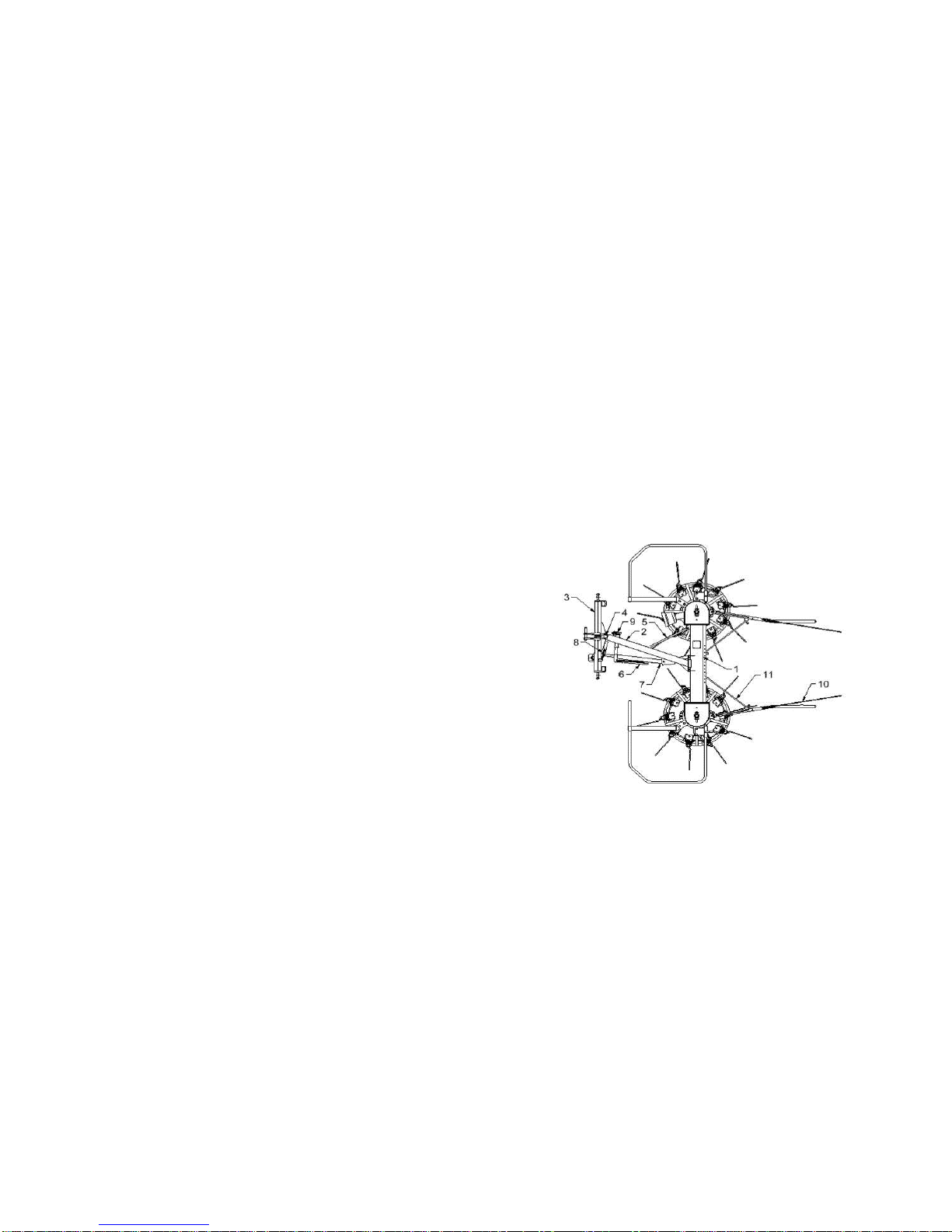
1 Main frame
2 Intermediary frame
3 Three-point suspension
4 Hinged bolt
5 Draw hook
6 Swath separator
7 Telescope tube
8 Rivet
9 Pin + spring
10 Swath collector
11 Attachment for swath collector
MOUNTING OF THE MACHINE
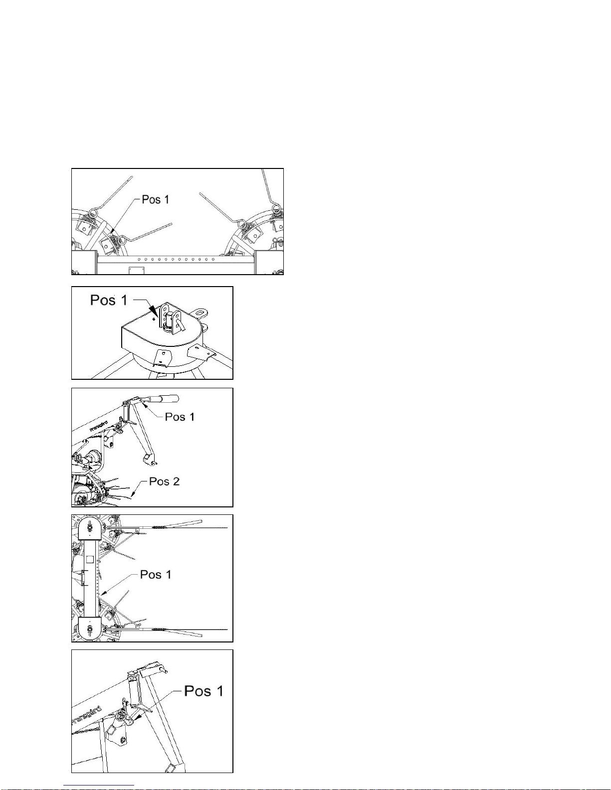
1) Intermediary frame 2is mounted on the main frame 1by means of
4 bolts and nuts. Tighten the bolts and tighten again after 2 hours
operation.
2) Three-point suspension 3is assembled and fastened to intermedi-
ary frame 2by means of hinged bolt 4. Place split pin.
3) Mount swath separator 6on intermediary frame 2. Mount spring on
swath separator and fasten with bolt.
4) Mount telescope tube 7on intermediary frame 2by means of rivets
and 2 split pins. The telescope tube is fastened to three-point suspen-
sion 3by means of rivet 8and 2 split pins.

-3-
DIRECTIONS FOR USE
Fastening of rotary turner to tractor :
Always use stabilizer or tighten the chains in order to prevent the
lifting arms from moving sideways during raking and transport, in order
to protect the power transmission shaft.
The length of the power transmission shaft must be checked in wor-
king position as well as in transport position, and if necessary it shall
be shortened. This will only be necessary in a very few cases.
ADJUSTMENT FOR SPREADING AND TURNING
Place all pick-up springs in spread-turn position Pos 1 as
shown in the illustration. (Check that all are in the same
position).
Adjust wheels in lower or middle position Pos 1. The machine will now
be in its highest position.
The upper bar of the tractor Pos 1 shall be fastened to the tree-point
suspension. Its length is correct, when the points of the pick-up
springs Pos 2 just touch the stubbles in front of the rotors and these
go at full speed. The pick-up springs reach their lowest position at 450
rpm.
The swath collectors may be used separately or both at the same time
to keep the swaths separated. They are used to advantage along the
edges of a field Pos 1.
Disconnect the locking device Pos 1 of the telescope tube.

-4-
ADJUSTMENT FOR RAKING AND LAYING IN SWATHS
All pick-up springs are placed in raking position Pos 1 as
shown in the illustration. (Check that all are in the same
position).
The wheel are placed in the upper or middle position Pos 1. The
machine will then be in its lowest position.
The upper bar of the tractor Pos 1 shall be fastened to the three-point
suspension. Its length is correct, when the points of the pick-up
springs Pos 2 just touch the stubbles in front of the rotors and these
go at full speed. The pick-up springs reach their lowest position at 450
rpm.
The swath collectors are set as shown Pos 1 in order to obtain an
uniform and loose swath.
Disconnect the locking device Pos 1 of the telescope tube.

-5-
TRANSPORT POSITION
During transport, the locking device Pos 1 must be engaged so in fact
that the machine will move directly behind the tractor. This way the
machine will be prevented from moving to the side.
WORKING POSITION
The rotary turner is built to move on the left side with no problems.
Whenmoving on the right side, the machine must be raised.

-6-
POSSIBLE APPLICATIONS
LUBRICATION AND MAINTANCE
1. After each 5 hours of work, the lubricator nipples in the
interior tube of the power transmission shaft must be
lubricated.
2. After each 10 hours of work, the 2 lubricator nipples of the
gearbox must be lubricated.
When the season is over, the machine must be cleaned and
made ready for the next season.
ORDERING OF SPARE PARTS
The spare part order must contain the following information.
1. Machine type
2. Spare part number and description - possibly dimensions and
number of parts.


Table of contents
Popular Lawn Mower Accessories manuals by other brands

Simplicity
Simplicity 1695163 Illustrated parts list

Simplicity
Simplicity SNAPPER 250 Z installation instructions

MASSEY FERGUSON
MASSEY FERGUSON 2500 Series parts manual

Stiga
Stiga DECK PARK 121 M - 4WD user manual

Simplicity
Simplicity 420 installation instructions

Hydro-Gear
Hydro-Gear ZT-3600 Service and repair manual