FRC DRY GEAR PLUS User instructions

DGA200 Rev160525
1
FIRE RESEARCH CORPORATION
www.reresearch.com
26 Southern Blvd., Nesconset, NY 11767
TEL 631.724.8888 FAX 631.360.9727 TOLL FREE 1.800.645.0074
Document Number:
XM-DGA2PM-R0A
DRYING SYSTEM
ASSEMBLY AND OPERATING MANUAL
DRY GEAR PLUS
w/Removable Hangers
DRY GEAR PRO

DGA200 Rev160525
2
CONTENTS
List of Tables
Table 1. Hardware...................................................................................................... 5
Table 2. Parts and Assemblies.................................................................................... 6
List of Figures
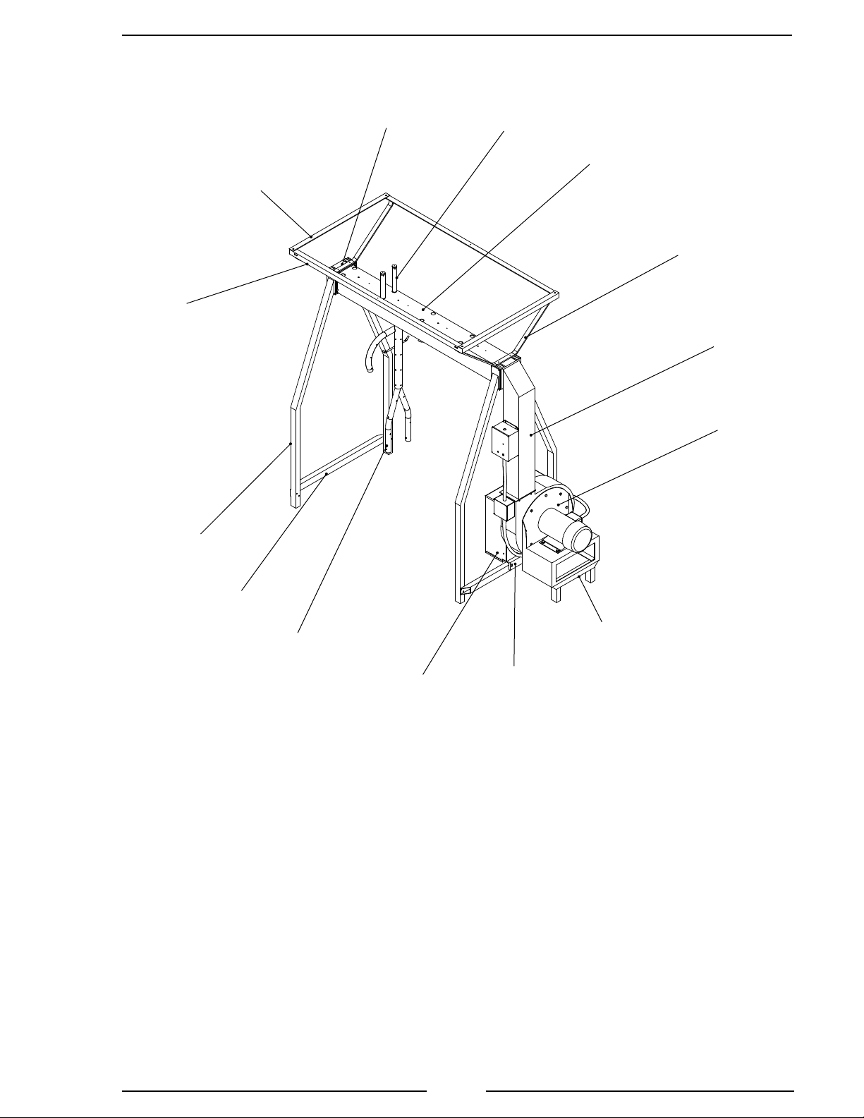
Figure 1. DryGear System Parts ................................................................................ 7
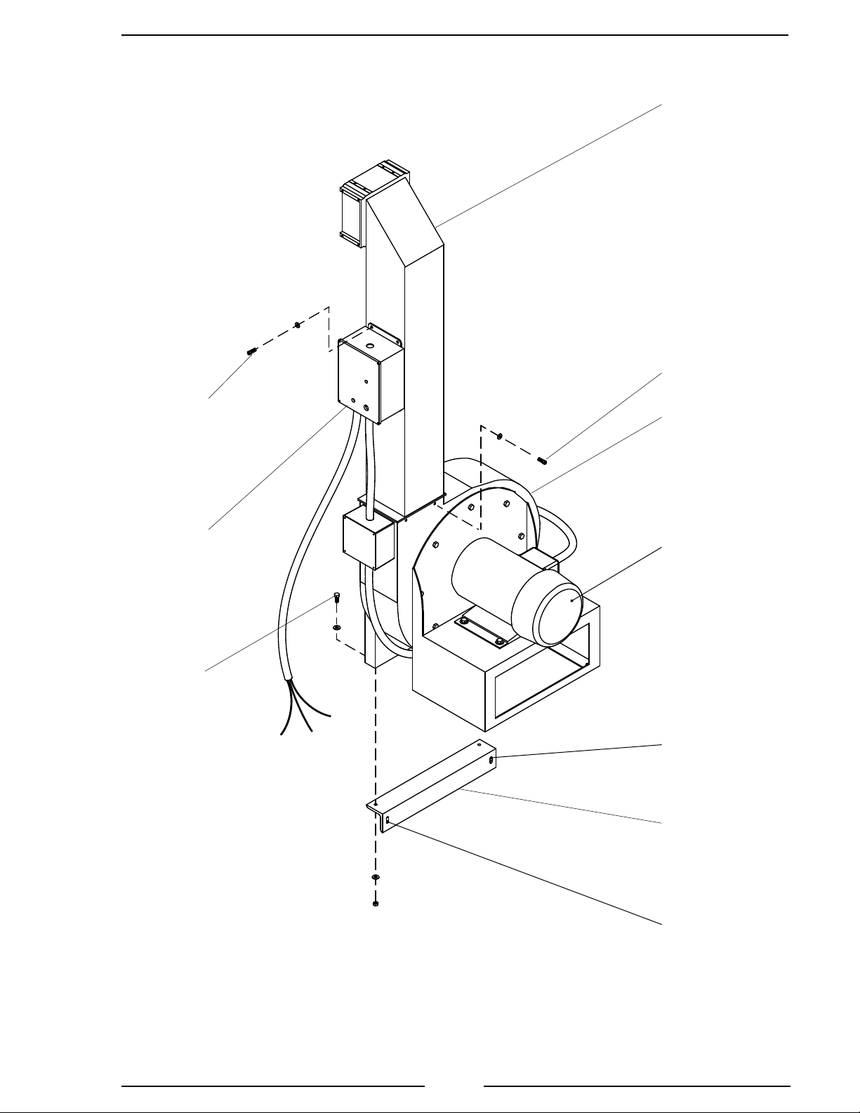
Figure 2. Blower Assembly and Transfer Tube ......................................................... 9
Figure 3. Manifold and Tent Frame Long Angles.................................................... 11
Figure 4. Leg Assemblies......................................................................................... 13
Figure 5. Blower Assembly Legs............................................................................. 15
Figure 6. Tent Frame................................................................................................ 17
Figure 7. Manifold, Tent Frame, and Mufer.......................................................... 19
Figure 8. Hanger and Glove Post............................................................................. 21
Figure 9. Tent Enclosure .......................................................................................... 23
Figure 10. Caster Kit................................................................................................ 25
Figure 11. Wiring Power.......................................................................................... 27
Figure 12. Control Box Panel .................................................................................. 29
Table of Contents
CONTENTS................................................................................................................ 2
INTRODUCTION ...................................................................................................... 3
Overview................................................................................................................ 3
Specications......................................................................................................... 4
ASSEMBLY INSTRUCTIONS.................................................................................. 5
Pre-Assembly......................................................................................................... 5
Tools Required....................................................................................................... 5
General Notes ........................................................................................................ 7
Assemble Blower Assembly and Transfer Tube.................................................... 8
Assemble Manifolds and Tent Frame Long Angles (6, 7, and 8 Station Only)... 10
Assemble Legs..................................................................................................... 12
Install Blower Assembly Legs ............................................................................. 14
Assemble Tent Frame .......................................................................................... 16
Assemble Manifold, Tent Frame, and Mufer..................................................... 18
Install Hanger and Glove Post ............................................................................ 20
Install Tent Enclosure .......................................................................................... 22
Install Optional Caster Kit ................................................................................... 24
WIRING POWER..................................................................................................... 26
OPERATION ............................................................................................................ 28

DGA200 Rev160525
3
INTRODUCTION
Overview
The DryGear system provides a closed environment for the drying of bunker gear,
hose, and loose equipment.
Warm air is delivered through a manifold to multiple stations with hanger and
glove assemblies. It is circulated within a tent enclosure to dry the interior and exterior
of coats, bunker pants, boots, helmets, gloves, hoods, and other equipment.
Tent Enclosure
The tent enclosure is made of cross weaved polyester vinyl with a clear front cover.
It is supported by an overhead frame and encloses the entire DryGear system rack.
The front cover has pull down zippers to seal the sides and rolls up to allow complete
access to the interior of the tent enclosure (6, 7, and 8 station congurations also have
a zipper down the middle of the front cover).
Blower Assembly
The blower assembly includes the blower and blower motor, heater element,
thermistor, and control box. It supplies warm air to the manifold through the transfer
tube. The air intake for the blower is located inside the tent enclosure to increase the
circulation of warm air. A mufer is attached to the air intake to reduce noise and
vibration. Ascreen on the intake prevents gear from being sucked in. Overheat protection
of the heater element is provided by an internal thermistor.
Control Box
The control box is mounted on the transfer tube. The BLOWER & HEATER
HOURS timer switch, SELECT switch, and HEATER SELECTED light are mounted
in the control box. Power to the control box for the DryGear system is supplied from
a local 220 volt 30 amp source.
Manifold
The manifold delivers forced air from the blower and transfer tube to the glove
posts, hangers, and DryGear system enclosure.
Options
An optional caster kit is available.
Ventilation
The DryGear system does not require separate ventilation. If the system is set up
in a small enclosed room, it is recommended that the room be vented to remove any
warm moist air.

DGA200 Rev160525
4
Specications
The DryGear system is available in 3, 4, 6, 7, and 8 station congurations.
Electrical Requirements
220 VAC; 30 AMP
Motor (3, 4, and 6 Station Conguration)
HP: 3
Volts: 208 / 230
Amps: 15.5 / 15.3
Motor (7 and 8 Station Conguration)
HP: 5
Volts: 220
Amps: 19.6
Heater
Power: 2400 Watts
Current Maximum: 10 AMPS
Thermistor: 180 °F cutoff
Timer: 6 Hours
Dimensions
Length: 3 station conguration: 71 inches
4 station conguration: 86 inches
6 station conguration: 121 inches
7 station conguration: 138 inches
8 station conguration: 153 inches
Width: 37 inches
Height: 84 inches (with caster kit option add 3 3/4 inches)
Material
Tubing: Aluminum square and round tubing
Enclosure: Rip-stop polyester vinyl

DGA200 Rev160525
5
ASSEMBLY INSTRUCTIONS
Pre-Assembly
Before assembling the DryGear system, verify that all loose hardware, parts, and
assemblies are on hand. Refer to the column in Tables 1 and 2 that reects the station
conguration to be assembled. (Some hardware, parts, or assemblies may be put together
at the factory prior to shipping.)
Tools Required
5/32 and 3/16 Inch Hex Key
7/16, 1/2, and 9/16 Inch Wrench
Rubber Mallet
Table 1. Hardware
Description 3-Station 4-Station 6-Station 7-Station 8-Station
Screw, Flat Head Socket
Cap, S/S, 1/4-20 x 1/2"
12 12 24 24 24
Screw, Socket Cap, S/S,
1/4-20 x 3/4"
28 28 44 44 44
Screw, Socket Cap, S/S,
1/4-20 x 1 1/4"
16 16 16 16 16
Screw, Socket Cap, S/S,
1/4-20 x 2 1/2"
88888
Nut, S/S, 1/4-20 8 8 8 8 8
Washer, Flat, S/S, 1/4" 52 52 68 68 68
Screw, Hex Head, S/S,
5/16-18 x 3/4"
44888
Screw, Hex Head, S/S,
5/16-18 x 2 1/4"
22222
Nut, S/S, 5/16-18 2 2 2 2 2
Washer, Flat, S/S, 5/16" 8 8 12 12 12
Washer, Lock, S/S, 5/16" 4 4 8 8 8
Screw, Hex Head, S/S,
3/8-16 x 1"
44444
Nut, S/S, 3/8-16 4 4 4 4 4
Washer, Flat, S/S, 3/8" 8 8 8 8 8
Washer, Lock, S/S, 3/8" 2 2 2 2 2

DGA200 Rev160525
6
Table 2. Parts and Assemblies
Notes:
1 Blower assembly mount, mufer, and 5th leg assembly may be installed on the blower
assembly from the factory.
2 Backing plates may be installed on the manifold from the factory.
3 Joining plates may be installed on one half of the manifold or tent frame long angles
from the factory.
Description 3-Station 4-Station 6-Station 7-Station 8-Station
Blower Assembly 11111
Blower Assembly Mount 111111
Mufer 111111
Leg Assembly 44444
5th Leg Assembly 111111
Leg Brace, Blower Side 1 1 1 1 1
Leg Brace, Non-Blower Side 1 1 1 1 1
Transfer Tube 11111
Manifold, 3-Station, 50" 1 0 2 1 0
Manifold, 4-Station, 65" 0 1 0 1 2
Backing Plate 244444
Manifold Joining Plate 300222
Endcap Casting 1 1 1 1 1
Glove Post 6 8 12 14 16
Hanger 3 4 6 7 8
Tent Frame Short Angle 2 2 2 2 2
Tent Frame Long Angle
(3-Station Length, 50")
20420
Tent Frame Long Angle
(4-Station Length, 65")
02024
Tent Frame End Support 2 2 2 2 2
Tent Frame Joining Plate 0 0 2 2 2
Tent 1 1 1 1 1
Caster Kit, Optional 1 1 1 1 1

DGA200 Rev160525
7
General Notes
• For the 6-station DryGear system two manifolds and two tent frame long
angles (50 inches) are put together with joining plates.
• For the 7-station DryGear system there are two different size manifolds and
two different size tent frame long angles (50 and 65 inches) put together
with joining plates.
• For the 8-station DryGear system two manifolds and two tent frame long
angles (65 inches) are put together with joining plates.
Figure 1. DryGear System Parts
Blower
Assembly
Mount
Blower
Assembly
Mufer
Leg
Assembly
5th Leg
Assembly
Leg
Brace
Transfer
Tube
Manifold
End Cap
Casting Glove Post
Hanger
Tent Frame
End Support
Tent Frame
Long Angle
Tent Frame
Short Angle

DGA200 Rev160525
8
Assemble Blower Assembly and Transfer Tube
NOTE: The blower assembly mount may be installed on the blower assembly
from the factory.
Parts Needed
1-Transfer Tube (1)
1-Blower Assembly (3)
1-Blower Assembly Mount (4)
8-Socket Cap Screw, 1/4-20, 3/4 inch (2)
8-Flat Washer, 1/4 inch
2-Hex Head Screw, 3/8-16, 1 inch (5)
4-Flat Washer, 3/8 inch
2-Lock Washer, 3/8 inch
2-Nut, 3/8-16
Procedure
1. Install transfer tube (1) on blower assembly (3) with four screws (2) and
washers.
2. Install control box (6) on chimney assembly (1) with four screws (2) and
washers.
NOTE: The blower assembly mount (4) has two slotted holes that allow for
adjustment when the blower assembly (3) is attached to the legs. Ensure
that the mount (4) is positioned so that the face with these holes is down
and toward the motor side.
3. Install blower assembly mount (4) on blower assembly (3) with two screws
(5), washers, and nuts.
End Procedure

DGA200 Rev160525
9
Figure 2. Blower Assembly and Transfer Tube
5
1
3
4
6Motor
Slotted Hole
Slotted Hole
2
2

DGA200 Rev160525
10
Assemble Manifolds and Tent Frame Long Angles (6, 7,
and 8 Station Only)
NOTE: The joining plates may be installed on one half of the manifold or
tent frame long angles from the factory.
Parts Needed
2-Manifold (1)
2-Manifold Joining Plate (3)
4-Tent Frame Long Angle (5)
2-Tent Frame Joining Plate (6)
12-Flat Head Socket Cap Screw, 1/4-20, 1/2 inch (4)
16-Socket Cap Screw, 1/4-20, 3/4 inch (2)
16-Flat Washer, 1/4 inch
Procedure
NOTE: The distance from the end of the manifold to the manifold glove
mount holes is different at each end. The glove post holes should be 4 1/4
inches from the manifold end that is attached to the joining plates.
1. Install manifold joining plates (3) between manifolds (1) with sixteen screws
(2) and washers.
2. Install tent frame joining plates (6) between tent frame long angles (5) with
twelve screws (4).
End Procedure

DGA200 Rev160525
11
Figure 3. Manifold and Tent Frame Long Angles
6 Station Manifold
8 Station Manifold
7 Station Manifold
1
3
1
2
4 1/4"
4 1/4"
5
5
4
6
NOTE: The distance between the glove post
holes and the correct end of the manifold at
the joint plate connection is 4 1/4 inches.

DGA200 Rev160525
12
Assemble Legs
NOTE: Do not tighten the screws completely until all parts are assembled.
NOTE: For the DRY GEAR Professional with the optional caster kit, make
sure the caster threaded leg plugs are installed at this time. (Refer to Install
Optional Caster Kit instructions.)
Parts Needed
4-Leg Assembly (1)
1-Endcap Casting (4)
1-Manifold (5)
1-Leg Brace, Blower Side (6)
1-Leg Brace, Non-Blower Side (8)
8-Socket Cap Screw, 1/4-20, 3/4 inch (2)
6-Socket Cap Screw, 1/4-20, 1 1/4 inches (3)
8-Socket Cap Screw, 1/4-20, 2 1/2 inches (7)
8-Nut, 1/4-20
26-Flat Washer, 1/4 inch
Procedure
NOTE: The blower side leg brace (6) has two holes for attaching the blower
assembly. Ensure that these holes are on the blower side as shown in
gure 4.
1. Connect leg braces (6 and 8) between each pair of leg assemblies (1) with eight
screws (7), washers, and nuts.
NOTE: The side lower screws that hold the leg assemblies (1) to the endcap
casting (4) do not have washers.
2. Connect endcap casting (4) to non-blower side leg assemblies (1) with eight
screws (2) and washers.
NOTE: The top inside holes through the endcap casting (4) into the manifold (5)
are not used at this time, the holes will be used for mounting the tent frame.
3. Install manifold (5) in endcap casting (4) with six screws (3) and washers.
End Procedure

DGA200 Rev160525
13
Figure 4. Leg Assemblies
3
7
Non-Blower Side
1
4
5
8
2
Blower Side
1
Holes
6

DGA200 Rev160525
14
Install Blower Assembly Legs
NOTE : The 5th leg assembly may be installed on the blower assembly from
the factory.
Parts Needed
1-5th Leg Assembly (3)
8-Socket Cap Screw, 1/4-20, 3/4 inch (1)
4-Flat Washer, 1/4 inch
2-Hex Head Screw, 5/16-18, 2 1/4 inches (4)
4-Flat Washer, 5/16 inch
2-Nut, 5/16-18
2-Hex Head Screw, 3/8-16, 1 inch (2)
4-Flat Washer, 3/8 inch
2-Nut, 3/8-16
Procedure
NOTE: The side lower screws that hold the blower side legs to transfer tube
do not have washers.
1. Connect blower side legs to transfer tube with eight screws (1) and washers.
Do not tighten screws.
2. Align blower assembly mount holes with leg brace holes and install two screws
(4), washers, and nuts. Do not tighten screws.
3. Tighten blower side legs to transfer tube screws (1).
4. Tighten blower assembly mount screws (4).
5. Install 5th leg assembly (3) with two screws (2), washers, and nuts.
End Procedure

DGA200 Rev160525
15
Figure 5. Blower Assembly Legs
Blower Side
Legs
Transfer
Tube
3
Blower Assembly
Mount
Leg Brace
1
Blower
Assembly
2
4

DGA200 Rev160525
16
Assemble Tent Frame
NOTE: Do not tighten the screws completely until all parts are assembled.
Parts Needed
2-Tent Frame Short Angle (1)
NOTE: For 6, 7, and 8 station conguration pairs of long angles are connected
together with a joining plate. (Refer to Assemble Manifold and Tent Frame
Long Angles instructions.)
2-Tent Frame Long Angle (2)
2-Tent Frame End Support (3)
12-Flat Head Socket Cap Screw, 1/4-20, 1/2 inch (4)
Procedure
NOTE: For 7 station conguration the 60-inch tent frame long angles are
connected to the same end support.
1. Connect two long angles (2) to end supports (3) with eight screws (4).
2. Connect short angles (1) to long angles (2) with four screws (4).
End Procedure

DGA200 Rev160525
17
Figure 6. Tent Frame
1 2
3
4

DGA200 Rev160525
18
Assemble Manifold, Tent Frame, and Mufer
NOTE : Mufer may be installed on the blower assembly from the factory.
Parts Needed
1-Mufer (3)
10-Socket Cap Screw, 1/4-20, 1 1/4 inches (1)
4-Socket Cap Screw, 1/4-20, 3/4 inches (2)
14-Flat Washer, 1/4 inch
Procedure
1. Install manifold in transfer tube top with six screws (1) and washers.
NOTE: For 7 station conguration mount the 60-inch tent frame long angle
side above the 60-inch manifold side.
2. Install tent frame with four screws (1) and washers.
3. Install mufer (3) on blower with four screws (2) and washers.
End Procedure

DGA200 Rev160525
19
Figure 7. Manifold, Tent Frame, and Mufer
Manifold
4-Station
Manifold Shown
Tent
Frame
3
View Rotated
90° for Clarity
Blower
Assembly
2
1
Transfer
Tube
Blower
Assembly

DGA200 Rev160525
20
Install Hanger and Glove Post
Parts Needed
NOTE: Quantities shown are for one station.
2-Glove Post (1)
1-Hanger (3)
1-Hex Head Screw, 5/16-18, 3/4 inch (2)
1-Flat Washer, 5/16 inch
1-Lock Washer, 5/16 inch
Procedure
NOTE: Make sure the hanger manifold air opening is towards the blower
assembly end of the manifold.
1. Slide hanger (3) into hole in bottom of manifold with hanger manifold air
opening towards the blower. Attach to top of manifold with screw (2) and
washers. The removable hanger (3a and 3b) installs the same way.
2. Screw glove post assembly (1) into top of manifold.
End Procedure
This manual suits for next models
1
Table of contents
Popular Dryer manuals by other brands

ConServ
ConServ CD 4040 W owner's manual

Parker
Parker PSE 120 user manual

Electrolux
Electrolux IQ-Touch EIMGD60LT installation guide

Hotpoint
Hotpoint Ultima Tumble Dryer User handbook

Frigidaire
Frigidaire FGQ1442E Factory parts catalog

Frigidaire
Frigidaire FAQE7011KW - 7 cu. Ft. Cycle Electric Dryer... Technical data sheet