-L'alimentation de la table de mixage DJ7 doit être branchée sur
secteur 220 Volts +/- 10%.
ATTENTION : Il est important de respecter l’ordre du raccordement pour
la sécurité des circuits de la table de mixage.
- The DJ7 mixer power supply must be connected on 220 Volts +/- 10% main.
CAUTION: It is important to respect this order of connection for the security
Of the electronic circuits of the mixer.
- Vérifier que la table et tous les appareils destinés à y être raccordés sont éteints, leurs volumes à zéro.
- Check that the mixer and other peripheral units are unplugged with output level at zero position.
- Connecter à l'aide des câbles blindés Cinch les différentes entrées -Platine Phono - Magnétophone à bande -
Tuner - CD - et les différentes sorties Générales et Enregistrement.
Pour les platines équipées d’une tétécommande à distance, vous devez raccorder celle ci à
L’entrée « START » correspondante.
ATTENTION : Ne pas introduire le secteur 220v dans le circuit « START » du mélangeur.
-Connect using screened cables all inputs on the mixer.
For the desks fitted with a remote control, you have to connect the remote control to the corresponding
START input.
CAUTION: Do not introduce the main 220v into the START circuit of the mixer.
- La table de mixage DJ7 dispose de 2 sorties Stéréo d'enregistrement:
La sortie - DJ : Programme musical sans le Micro "DJ".
La sortie +DJ : Programme musical avec le micro "DJ".
Les sorties « -DJ /+DJ » ont un niveau fixe, indépendant des Masters Stéréo1 et Stéréo2.
- The DJ7 comes with 2 stereo record output:
The - DJ output : Program without DJ Mic
The +DJ output : Program with DJ Mic.
The “-DJ/+DJ” outputs have a fix level, independent of the Stereo1 and Stereo2 Masters.
- Connecter les Microphones à l'aide de câble blindé XLR .
-Connect Microphones with screened XLR cable .
IN MIC.DJ7
- Mettre les différents appareils en service:
1/ Les Sources -2/ La table -3/ Les Amplificateurs.
- Switch ON all the different units:
1/ Source unit’s -2/ The Mixer -3/ The Amplifier.
AMPLI OUT STEREO DJ7
AMPLI OUT STEREO DJ7
- Ajuster le volume des amplificateurs à un niveau moyen, puis les niveaux de Sortie de la console à l'aide du
potentiomètre Master Stéréo1.
- Adjust amplifier volume on a average level, then the Console Master .
NOTA: Les amplificateurs de sortie de la DJ7 ont une réserve de +12 dB, il n'est donc pas conseillé
de positionner les potentiomètres Master au maximum.
NOTA: The DJ7 output amplifier have a +12 dB gain reserve. So please don't set the Master
on upper position.
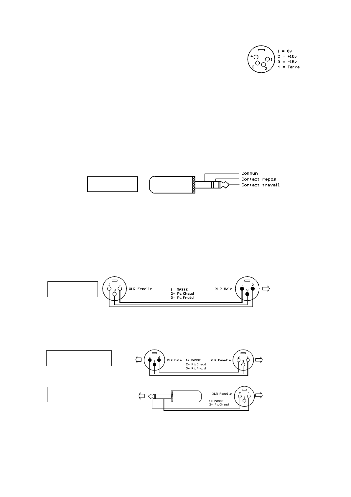
CABLAGE START
CABLAGE MICRO
MIC. WIRING
CABLAGE SYMETRIQUE
BALANCED WIRING
CABLAGE ASYMETRIQUE
UNBALANCED WIRING