freightliner 114SD Release note

Driver’s Manual
108SD and 114SD
Part Number STI-496
Publication Number STI-496-6

Introduction
This manual provides information needed to operate
and understand the vehicle and its components.
More detailed information is contained in the Owner’s
Warranty Information for North America booklet, and
in the vehicle’s workshop and maintenance manuals.
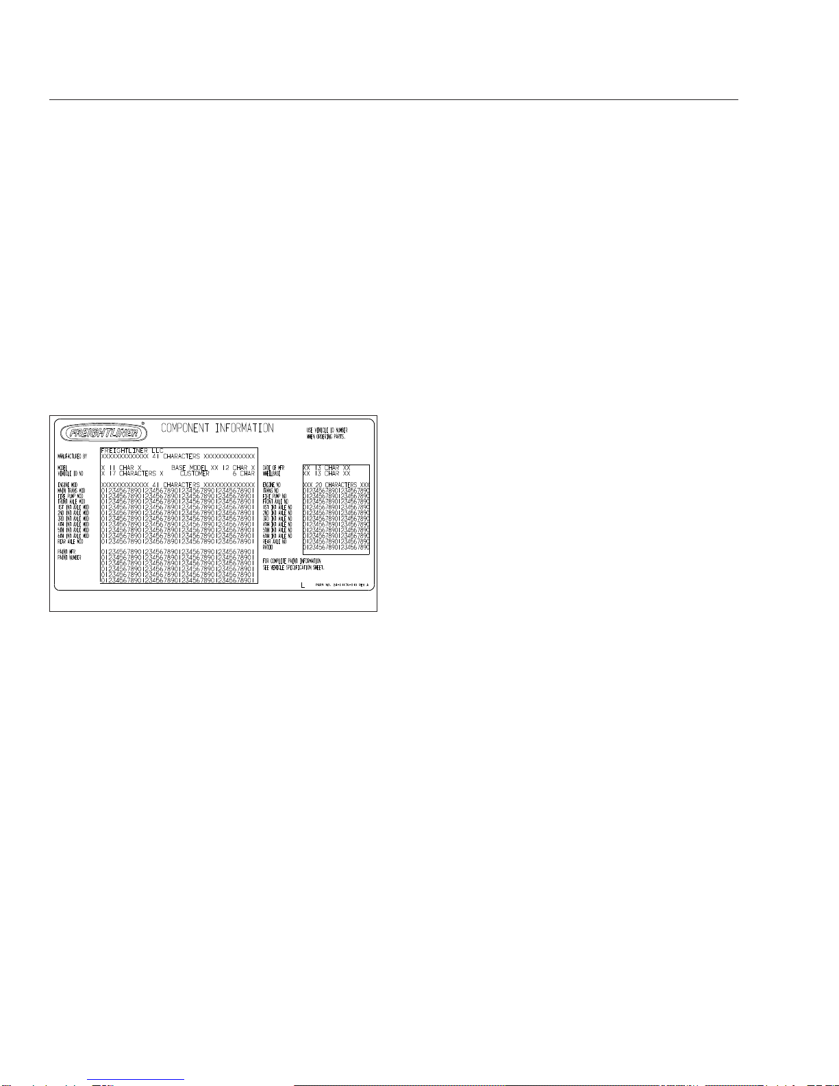
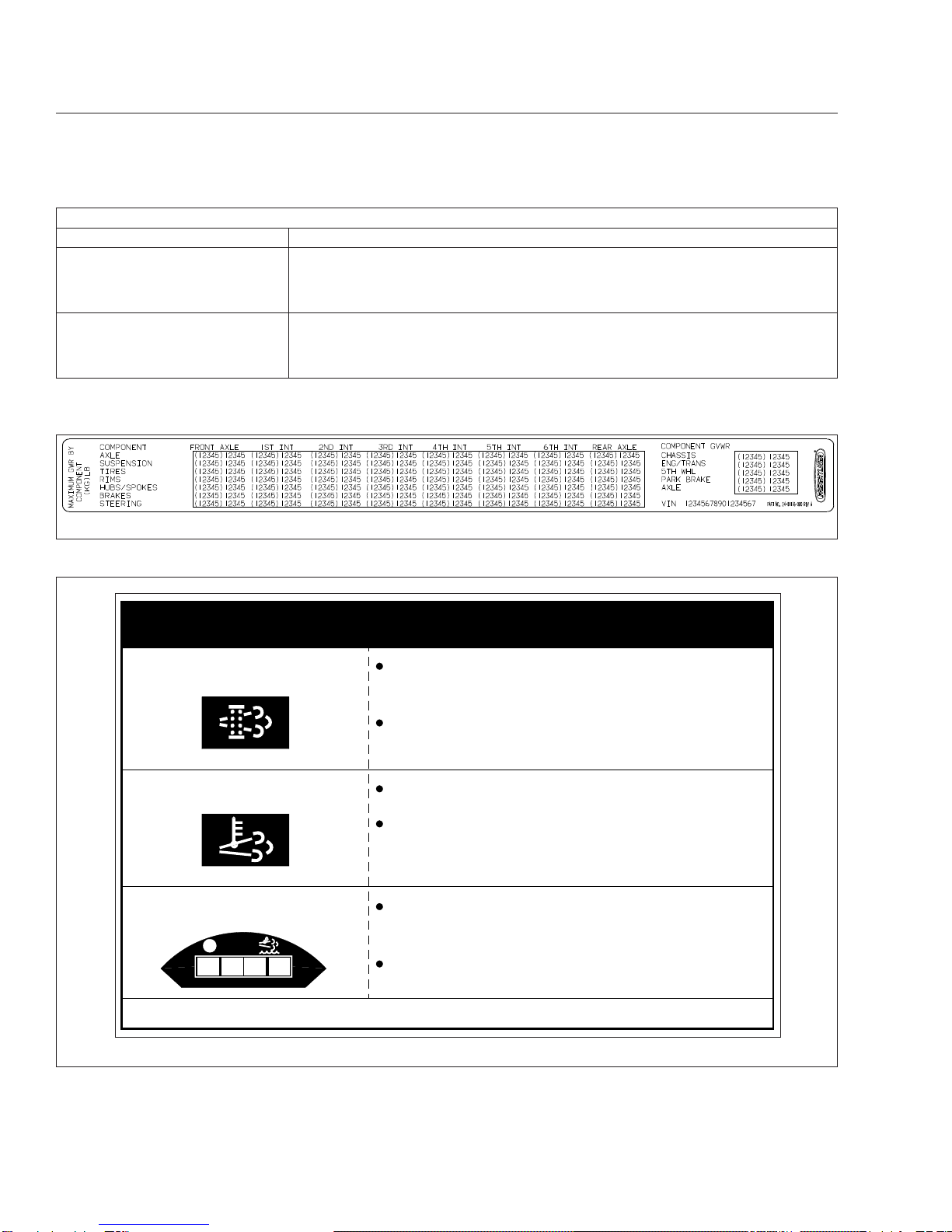
Custom-built Freightliner vehicles are equipped with
various chassis and cab components. Not all of the
information contained in this manual applies to every
vehicle. For details about components in your ve-
hicle, refer to the chassis specification pages in-
cluded in all new vehicles and to the vehicle specifi-
cation decal, located inside the vehicle.
For your reference, keep this manual in the vehicle
at all times.
IMPORTANT: Descriptions and specifications in
this manual were in effect at the time of printing.
Freightliner Trucks reserves the right to discon-
tinue models and to change specifications or
design at any time without notice and without
incurring obligation. Descriptions and specifica-
tions contained in this publication provide no
warranty, expressed or implied, and are subject
to revisions and editions without notice.
Environmental Concerns and
Recommendations
Whenever you see instructions in this manual to dis-
card materials, you should first attempt to reclaim
and recycle them. To preserve our environment, fol-
low appropriate environmental rules and regulations
when disposing of materials.
Event Data Recorder
This vehicle is equipped with one or more devices
that record specific vehicle data. The type and
amount of data recorded varies depending on how
the vehicle is equipped (such as the brand of engine,
if an air bag is installed, or if the vehicle features a
collision avoidance system, etc.).
This vehicle is equipped with an event data recorder
(EDR). The main purpose of an EDR is to record
data in certain crash or near-crash situations, such
as air bag deployment or hitting a road obstacle, that
will assist in understanding how a vehicle’s systems
performed. The EDR is designed to record data re-
lated to vehicle dynamics and safety systems for ap-
proximately 60 seconds. This data can help provide
a better understanding of the circumstances in which
crashes and injuries occur. Data recorded includes
the following items:
•how various systems in the vehicle were oper-
ating
•engine system information
•how far (if at all) the driver was depressing the
accelerator
•if the driver was depressing the brake pedal
•how fast the vehicle was traveling
NOTE: Data is not recorded by the EDR under
normal driving conditions. Personal data such
as name, gender, age, and crash location are
not recorded. However, other parties such as
law enforcement could combine the EDR data
with the type of personally identifying data rou-
tinely acquired during a crash investigation.
To read data recorded by an EDR, special equipment
is required, and access to the vehicle or the EDR is
needed. In addition to the vehicle manufacturer, other
parties that have the special equipment, such as law
enforcement, can read the information if they have
access to the vehicle or the EDR.
Emissions and Fuel Efficiency
Compliance
This vehicle must be regularly inspected and main-
tained as indicated in the 108SD and 114SD Mainte-
nance Manual, and in the Pre- and Post-Trip Inspec-
tions and Maintenance chapter in this manual, in
order to continue satisfactory performance and en-
sure coverage of the vehicle under the manufactur-
er’s warranty. Many maintenance procedures ensure
that the vehicle and engine continue to comply with
applicable emissions standards. Maintenance proce-
dures, using components engineered to comply with
greenhouse gas emissions and fuel efficiency regula-
tions, may be performed by an authorized Daimler
Trucks North America dealer, an independent outlet,
or the vehicle owner or operator.
The vehicle owner is responsible for determining the
suitability of replacement components to maintain
Foreword
STI-496-6 (5/15)
Part Number STI-496
Printed in U.S.A.

compliance with federal and local jurisdictional regu-
lations. Components including, but not limited to,
tires, cab/sleeper side extenders, chassis fairings,
bumper, hood, vehicle speed limiters, and idle reduc-
tion timers are specifically designed and manufac-
tured to exacting standards for regulatory fuel effi-
ciency and greenhouse gas emissions compliance. It
is important that these components are always re-
placed with components that meet or exceed the per-
formance of the originally installed components.
Customer Assistance Center
Having trouble finding service? Call the Customer
Assistance Center at 1-800-385-4357 or 1-800-FTL-
HELP. Call night or day, weekdays or weekends, for
dealer referral, vehicle information, breakdown coor-
dination, or Fleetpack assistance. Our people are
knowledgeable, professional, and committed to fol-
lowing through to help you keep your truck moving.
Reporting Safety Defects
If you believe that your vehicle has a defect which
could cause a crash or could cause injury or
death, you should immediately inform the National
Highway Traffic Safety Administration (NHTSA) in
addition to notifying Daimler Trucks North America
LLC.
If NHTSA receives similar complaints, it may open
an investigation, and if it finds that a safety defect
exists in a group of vehicles, it may order a recall
and remedy campaign. However, NHTSA cannot
become involved in individual problems between
you, your dealer, or Daimler Trucks North America
LLC.
To contact NHTSA, you may call the Vehicle
Safety Hotline toll-free at 1-888-327-4236 (TTY:
1-800-424-9153); go to www.safercar.gov;or
write to: Administrator, NHTSA, 1200 New Jersey
Avenue, SE, Washington, DC 20590. You can also
obtain other information about motor vehicle safety
from www.safercar.gov.
Canadian customers who wish to report a safety-
related defect to Transport Canada, Defect Investi-
gations and Recalls, may telephone the toll-free
hotline 1-800-333-0510, or contact Transport
Canada by mail at: Transport Canada, ASFAD,
Place de Ville Tower C, 330 Sparks Street, Ot-
tawa, Ontario, Canada K1A 0N5.
For additional road safety information, please visit
the Road Safety website at: www.tc.gc.ca/
roadsafety.
© 2011-2015 Daimler Trucks North America LLC. All rights reserved. Daimler Trucks North America LLC is a Daimler
company.
No part of this publication, in whole or part, may be translated, reproduced, stored in a retrieval system, or transmitted
in any form by any means, electronic, mechanical, photocopying, recording, or otherwise, without the prior written per-
mission of Daimler Trucks North America LLC. For additional information, please contact Daimler Trucks North
America LLC, Service Systems and Documentation, P.O. Box 3849, Portland OR 97208–3849 U.S.A. or refer to
www.Daimler-TrucksNorthAmerica.com and www.FreightlinerTrucks.com.
Foreword

Contents
Chapter Page
Introduction, Environmental Concerns and Recommendations,
Event Data Recorder, Emissions and Fuel Efficiency Compliance,
Customer Assistance Center, Reporting Safety Defects .................... Foreword
1Vehicle Identification ...................................................... 1.1
2Vehicle Access .......................................................... 2.1
3Electrical System ........................................................ 3.1
4Instruments ............................................................. 4.1
5Driver Controls .......................................................... 5.1
6Seats and Restraints ..................................................... 6.1
7Climate Control .......................................................... 7.1
8Cab Features ........................................................... 8.1
9Engine Starting, Operation, and Shutdown .................................... 9.1
10 Optional Engine Systems ................................................. 10.1
11 Emissions and Fuel Efficiency ............................................. 11.1
12 Brake Systems ......................................................... 12.1
13 Manual Transmissions and Clutch .......................................... 13.1
14 Automated and Automatic Transmissions .................................... 14.1
15 Drive Axles ............................................................ 15.1
16 Steering System ........................................................ 16.1
17 Fifth Wheels ........................................................... 17.1
18 Trailer Couplings ........................................................ 18.1
19 Natural Gas Vehicle ..................................................... 19.1
20 Pre- and Post-Trip Checklists ............................................. 20.1
21 Pre- and Post-Trip Inspections and Maintenance .............................. 21.1
22 Cab Appearance ........................................................ 22.1
23 Headlight Aiming ........................................................ 23.1
24 In an Emergency ....................................................... 24.1
Index .................................................................. I.1

1
Vehicle Identification
Component Information Label ....................................................... 1.1
Federal Motor Vehicle Safety Standard Labels .......................................... 1.1
Canadian Motor Vehicle Safety Standard Labels ........................................ 1.1
Component GWR Label ............................................................ 1.1
Emissions Labels ................................................................. 1.1

Component Information Label
NOTE: Labels shown in this chapter are ex-
amples only. Actual specifications may vary from
vehicle to vehicle.
The component information label lists the vehicle
model, identification number, and major component
models. It also lists the major assemblies and instal-
lations shown on the chassis specification sheet.
One copy of the component information label is at-
tached to the inside of the glove box; another copy is
inside the rear cover of the Owner’s Warranty Infor-
mation for North America booklet. An illustration of
the label is shown in Fig. 1.1.
Federal Motor Vehicle Safety
Standard Labels
NOTE: Due to the variety of Federal Motor Ve-
hicle Safety Standard (FMVSS) certification re-
quirements, not all of the labels shown will apply
to your vehicle.
Tractors with or without fifth wheels purchased in the
U.S. are marked as certified by means of an FMVSS
certification label. See Fig. 1.2. This label is attached
to the driver-side B-pillar, as shown in Fig. 1.3.
The tire and rim portion of the FMVSS certification
label certifies suitable tire and rim combinations that
can be installed on the vehicle, for the given gross
axle weight rating. Tires and rims installed on the
vehicle at the time of manufacture may have a higher
load capacity than that certified by the tire and rim
label. If the tires and rims currently on the vehicle
have a lower load capacity than that shown on the
tire and rim label, then the tires and rims determine
the load limitations on each of the axles.
Trucks built without a cargo body that are intended
for service in the U.S. have an incomplete vehicle
certification label attached by the final-stage manu-
facturer. See Fig. 1.4. This label will be attached to
the incomplete vehicle document included with the
vehicle, and certifies that the vehicle conforms to all
applicable FMVSS regulations in effect on the date of
completion.
Canadian Motor Vehicle Safety
Standard Labels
In Canada, tractors with fifth wheels are marked as
certified by means of a statement of compliance label
with the Canadian National Safety Mark attached to
the driver-side door frame B-pillar. See Fig. 1.5.
Trucks built without a cargo body and tractors built
without a fifth wheel that are intended for service in
Canada have an incomplete vehicle certification label
attached to the driver-side B-pillar. After completion
of the vehicle, a complete certification label must be
attached by the final-stage manufacturer to certify
that the vehicle conforms to all applicable Canada
Motor Vehicle Safety Standard (CMVSS) regulations
in effect on the date of completion.
Component GWR Label
The component GWR label is located on the
passenger-side B-pillar. The label provides maximum
GWR ratings for each component.
See Fig. 1.6 for a typical component GWR label.
Emissions Labels
Aftertreatment System Indicators
Label
Engines and vehicles manufactured after December
31, 2006 and domiciled in the U.S. or Canada are
required to meet all EPA regulations effective as of
the vehicle build date, and are equipped with an
emission aftertreatment system (ATS). Vehicles do-
miciled outside of the U.S. and Canada may not
have aftertreatment equipment, depending upon local
statutory emissions guidelines. See Table 1.1.
02/20/2012 f080176
Fig. 1.1, Component Information Label
Vehicle Identification
1.1

A warning label on the driver-side visor contains im-
portant warning indicators in the instrument cluster
that pertain to the ATS. See Fig. 1.7.
It is a violation of U.S. federal law to alter exhaust
plumbing, ATS, or other components in any way that
would bring the engine/vehicle out of compliance with
certification requirements [Ref: 42 U.S.C. S7522(a)
(3)]. It is the owner’s responsibility to maintain the
vehicle so that it conforms to EPA regulations.
EPA Noise Emission Control Label
A vehicle noise emission control label (Fig. 1.8)is
located on the driver-side B-pillar as shown in
Fig. 1.3. It is the owner’s responsibility to maintain
the vehicle so that it conforms to EPA regulations.
IMPORTANT: Certain Freightliner incomplete
vehicles may be produced with incomplete noise
control hardware. Such vehicles will not have a
vehicle noise emission control information label.
For such vehicles, it is the final-stage manufac-
turer’s responsibility to complete the vehicle in
conformity to U.S. EPA regulations (40 CFR Part
205) and label it for compliance.
02/20/2012 f080177
Fig. 1.2, Vehicle Certification Label
02/28/2012 f080182
1
2
1. EPA Noise Emission Control Label
2. FMVSS Certification Label
Fig. 1.3, Label Locations
f080180
02/28/2012
Fig. 1.4, Incomplete Vehicle Certification Label
f080024
10/10/2006
Fig. 1.5, Canadian National Safety Mark
Vehicle Identification
1.2

Applicable Emissions System Based on Build Date and EPA Regulations
Build Date Regulation: Emissions Components
January 1, 2010–December 31,
2012
EPA10 (reduce NOx emissions to 0.2 g/bhp-hr): Aftertreatment device (ATD)
containing a diesel particulate filter that traps soot and ash, with selective catalyst
reduction (SCR) technology that utilizes diesel exhaust fluid (DEF) to convert NOx to
nitrogen and water vapor.
From March 5, 2012
GHG14: Aerodynamic and fuel efficiency components including, but not limited to,
tires, cab/sleeper side extenders, chassis fairings, bumper, hood, vehicle speed
limiters, and idle reduction timers specifically designed to meet regulatory fuel
efficiency and greenhouse gas emissions standards.
Table 1.1, Applicable Emissions System Based on Build Date and EPA Regulations
02/20/2012 f080178
Fig. 1.6, Component GWR Label
DPF Regen Needed
Hot Exhaust
DEF Refill Needed
Diesel Particulate Filter (DPF)
regeneration is needed.
If flashing, regenerate as soon as
possible. Engine derate possible.
Hot exhaust can cause fire.
Keep flammables and people away
from exhaust.
Diesel Exhaust Fluid (DEF) level is
low. Engine derate likely.
Refill tank with certified DEF.
24−01656−000
IMPORTANT
DEF
11/30/2010 f080162
See operator’s manual for complete instructions.
Fig. 1.7, ATS Indicators
Vehicle Identification
1.3

Vehicle Emission Control Information
Label
Model year 2013 and later vehicles meet additional
requirements as specified by federal greenhouse gas
and fuel efficiency regulations (GHG14). These ve-
hicles are equipped with components that increase
fuel efficiency and reduce GHG emissions. Compo-
nents may include, but are not limited to, low-rolling
resistance tires; aerodynamic devices such as hood,
cab side extenders, and fuel tank fairings; vehicle
speed limiters; and idle shutdown timers.
A Vehicle Emission Control Information Label is lo-
cated on the driver-side door. See Fig. 1.9.Itisthe
owner’s responsibility to maintain the vehicle so that
it conforms to EPA and NHTSA regulations.
Certified Clean Idle Label
The California Air Resources Board (CARB) requires
model year 2008 and newer heavy-duty diesel en-
gines to be equipped with a non-programmable en-
gine shutdown system that automatically shuts down
the engine after five minutes of idling in order to limit
emissions of particulate matter and NOx.
Certified vehicles are equipped with a label placed
near the bottom edge of the driver-side door. See
Fig. 1.10.
10/06/98 f080026
24−00273−020
VEHICLE NOISE EMISSION CONTROL INFORMATION
FREIGHTLINER CORPORATION
THIS VEHICLE CONFORMS TO U.S. EPA REGULATIONS FOR NOISE EMISSION
APPLICABLE TO MEDIUM AND HEAVY TRUCKS.
THE FOLLOWING ACTS OR THE CAUSING THEREOF BY ANY PERSON ARE PROHIBITED BY
THE NOISE CONTROL ACT OF 1972:
A. THE REMOVAL OR RENDERING INOPERATIVE, OTHER THAN FOR PURPOSES OF
MAINTENANCE, REPAIR, OR REPLACEMENT, OF ANY NOISE CONTROL DEVICE OR
ELEMENT OF DESIGN (LISTED IN THE OWNER’S MANUAL) INCORPORATED INTO THIS
VEHICLE IN COMPLIANCE WITH THE NOISE CONTROL ACT.
B. THE USE THIS VEHICLE AFTER SUCH DEVICE OR ELEMENT OF DESIGN HAS
BEEN REMOVED OR RENDERED INOPERATIVE.
DATE OF MANUFACTURE
01/96
Fig. 1.8, Vehicle Noise Emission Control Label
f080181
02/29/2012
MANUFACTURED BY:
VIN:
VEH FAMILY CD:
GVWR−KG
GVWR−LBS
REGULATORY CLASS:
EMISSION CONTROL IDENTIFIERS:
DATE OF MANUFACTURE:
VEHICLE EMISSION CONTROL INFORMATION
THIS VEHICLE COMPLIES WITH U. S. EPA REGULATIONS FOR XXXX HEAVY DUTY VEHICLES.
SEE OWNER’S MANUAL FOR PROPER MAINTENANCE OF THIS VEHICLE. U PART NO. 24−01177−060 REV A
Fig. 1.9, Vehicle Emission Control Information Label
CERTIFIED
CLEAN IDLE
02/20/2012 f080179
Fig. 1.10, CARB Clean Idle Label
Vehicle Identification
1.4

2
Vehicle Access
Door Locks and Handles ........................................................... 2.1
Cab Entry and Exit ................................................................ 2.2
Back-of-Cab Access ............................................................... 2.4
Hood Opening and Closing ......................................................... 2.5

Door Locks and Handles
One key operates the ignition switch and all of the
door locks.
IMPORTANT: Each key is numbered. Record
the number so a duplicate key can be made, if
needed.
To unlock the driver’s door from outside the cab, in-
sert the key in the lockset and turn it one-quarter turn
clockwise (Fig. 2.1). To remove the key, turn it coun-
terclockwise to its original position. Pull out on the
door pull handle to open the door.
To unlock the passenger’s door from outside the cab,
insert the key in the lockset and turn it one-quarter
turn counterclockwise. Turn the key clockwise to the
original position to remove it.
To open the door from the inside, lift up on the door
lever. This will unlatch the door whether or not it is
locked. See Fig. 2.2.
NOTE: The cab door locks can be operated
when the doors are open.
To lock a door from outside the cab, insert the key in
the lockset and turn it in the direction opposite to the
unlocking direction (counterclockwise for the driver’s
door, clockwise for the passenger’s door). Close the
door if it is open.
To lock either door from inside the cab, push the lock
button downwards (Fig. 2.3). To unlock the door
without unlatching it, push the lock button upwards. A
red dot will show below the lock button when it is
unlocked.
10/22/2001 f720397
1
2
3
1. Key
2. Lock
3. Door Pull Handle
Fig. 2.1, Exterior Door Handle
10/25/2001 f720398
12
34
5
To open the door from the inside, lift up on the door lever
(arrow).
1. Lock Button
2. Armrest/Handle
3. Door Lever
4. Window Crank
5. Inner Door Grab
Handle (optional)
Fig. 2.2, Door Interior
10/24/2001 f720401
1
2
3
Move the button down to lock, and up to unlock (arrows).
The door is unlocked when the red dot shows.
1. Door
2. Lock Button
3. Red Dot
Fig. 2.3, Door Lock Button
Vehicle Access
2.1

Cab Entry and Exit
For ease of entry and exit, there are three grab
handles, one on the A-pillar, one on the inner B-pillar,
and an optional one on the inside of the door. In ad-
dition, the steering wheel may be used to provide
secure handholds. There are at least two access
steps to provide secure footholds.
NOTE: The A-pillar grab handle is not installed
on the driver’s side.
The grab handles, access steps, and steering wheel
are all part of the cab access system. Use these
"helping hands" when getting into, or out of, the cab.
They will increase your security and comfort.
Entering from the Driver’s Side
To enter the cab on the driver’s side, use the grab
handles and access steps as follows:
1. Open the driver-side door and place anything
that you are carrying in the cab.
2. Grasp the B-pillar grab handle with your right
hand. See Fig. 2.4.
3. Grasp the door grab handle with your left hand.
4. Place your right foot on the bottom step, and pull
yourself up.
5. Place your left foot on the top step.
6. Grasp the steering wheel with your left hand, and
step up.
7. Step into the cab with your right foot first, and
grasp the steering wheel with your right hand.
Exiting from the Driver’s Side
To exit the cab from the driver’s side, use the grab
handles and access steps as follows:
IMPORTANT: Do not attempt to exit the cab
while carrying any items in your hands.
1. If you wish to take any items with you out of the
cab, place them in an accessible location on the
seat or cab floor. Make sure they will not get in
your way as you exit.
WARNING
Always face in when exiting the cab. Do not at-
tempt to exit with your back to the cab, as you
would going down a flight of stairs. It is easier to
slip or lose your balance. If you slip when exiting
in this way, there is a greater likelihood of per-
sonal injury.
2. Grasp the steering wheel with both hands, place
your left foot on the top step, then stand on the
threshold facing into the cab. See Fig. 2.4.
3. Using your right hand, grasp the B-pillar grab
handle.
4. Move your right foot to the bottom step.
12/20/2010 f720726
1
2
3
4
5
6
7
1. Bottom Step
2. Top Step
3. Door Grab Handle
4. Armrest
5. Steering Wheel
6. Sidewall Grab Handle
7. B-Pillar Grab Handle
Fig. 2.4, Cab Access System, Driver’s Side
Vehicle Access
2.2

5. Move your left hand to the door grab handle.
6. Step to the ground with your left foot first.
7. Retrieve from the cab any items that you wish to
take with you.
Entering from the Passenger’s Side
To enter the cab on the passenger side, use the grab
handles and access steps as follows:
1. Open the passenger-side door and place any-
thing that you are carrying in the cab.
2. Using your left hand, grasp the B-pillar grab
handle. See Fig. 2.5.
3. Using your right hand, grasp the door grab
handle.
4. Place your left foot on the bottom step.
5. Place your right foot on the top step.
6. Move your right hand to the A-pillar grab handle.
7. Place your left foot on the top step, then move
your left hand to the A-pillar grab handle.
8. Step into the cab with your left foot first.
Exiting from the Passenger’s Side
To exit the cab from the passenger side, use the
grab handles and access steps as follows:
IMPORTANT: Do not attempt to exit the cab
while carrying any items in your hands.
1. If you wish to take any items with you out of the
cab, place them in an accessible location on the
seat or cab floor. Make sure they will not get in
your way as you exit.
WARNING
Always face in when exiting the cab. Do not at-
tempt to exit with your back to the cab, as you
would going down a flight of stairs. It is easier to
slip or lose your balance. If you slip when exiting
in this way, there is a greater likelihood of per-
sonal injury.
2. Grasp the A-pillar grab handle with both hands,
then place your right foot on the top step while
standing up from the seat facing inward. See
Fig. 2.5.
3. Place your left foot on the top step.
4. Move your left hand to the B-pillar grab handle.
5. Move your left foot to the bottom step.
6. Move your right hand to the door grab handle.
7. Step to the ground with your right foot first.
8. Retrieve from the cab any items that you wish to
take with you.
12/17/2010 f720727
1
2
3
4
5
6
7
1. Bottom Step
2. Top Step
3. B-Pillar Grab Handle
4. ATD Grab Handle
(optional)
5. A-Pillar Grab Handle
6. Armrest
7. Door Grab Handle
Fig. 2.5, Cab Access System, Passenger’s Side and
Back of Cab
Vehicle Access
2.3

Back-of-Cab Access
WARNING
External surfaces of the exhaust system remain
hot after the engine has been shut down. When
accessing the back of the cab or sleeper, do not
touch any part of the exhaust system, or severe
burns could occur.
When trailer air and electrical connections cannot be
reached conveniently from the ground, Federal Motor
Carrier Safety Regulations require commercial carri-
ers to provide back-of-cab access.
Optional grab handles are mounted on each cab
sidewall, or on the left sidewall only. See Fig. 2.6.
Steps are mounted either on the fuel tank(s) or on
metal brackets. When a deck plate is necessary, it is
mounted across the top of the frame rails.
IMPORTANT: Climb onto, and down from, back-
of-cab access facing in toward the vehicle, as
you would on a ladder. Do not climb up or down
facing out away from the vehicle.
WARNING
Wet or dirty shoe soles greatly increase the
chance of slipping or falling. If your soles are wet
or dirty, be especially careful when climbing
onto, or leaving, the back-of-cab area.
Always maintain three-point contact with the
back-of-cab access supports while entering and
exiting the back-of-cab area. Three-point contact
means both feet and one hand, or both hands
and one foot, on the grab handles, steps, and
deck plates. Other areas are not meant to sup-
port back-of-cab access, and grabbing or step-
ping in the wrong place could lead to a fall, and
personal injury.
Be careful not to get hands or feet tangled in
hoses or other back-of-cab equipment. Careless-
ness could cause a person to trip and fall, with
possible injury.
Climbing Up to Back-of-Cab
When climbing onto the deck plate, do the following:
1. Grasp the sidewall grab handle with both hands.
Reach up as far as is comfortable.
2. Place one foot on the bottom step and pull your-
self up.
3. Place your other foot on the top step.
4. Move your lower hand to a higher position on the
grab handle.
5. Step onto the deck plate.
Climbing Down from Back-of-Cab
To climb down from the back-of-cab area:
1. Grasp the sidewall grab handle with both hands.
2. Step one foot at a time onto the top step.
3. Move your upper hand to a lower position on the
grab handle.
4. Move one foot to the bottom step.
12/17/2010 f602442
1
1
2
3
1. Steps
2. Grab Handle
3. Deck Plate
Fig. 2.6, Back-of-Cab Access Supports (typical)
Vehicle Access
2.4

5. Move your upper hand to a lower position on the
grab handle.
6. Step to the ground with your upper foot first.
Hood Opening and Closing
The hood can be raised to a full-open position. A
strut helps you to raise the hood, and to lower it to
the operating position. Hood restraint cables prevent
the hood from overtravel. The hood strut limits the
closing speed. In the operating position, the hood is
secured to the cab-mounted cowl by a hold-down
latch on each side of the hood.
To Tilt the Hood
1. Apply the parking brakes.
2. Release both hood hold-down latches by pulling
the ends outward. See Fig. 2.7.
NOTICE
Do not let the hood free-fall to the full-open posi-
tion. To do so could cause damage to the hood
or hood straps.
3. Standing in front of the hood, raise the rear of
the hood upward until it reaches the over-center
position (45 degrees from vertical). See Fig. 2.8.
Then slowly bring it to a stop.
To Return the Hood
1. Push the hood over center.
2. As the hood goes over center, the strut automati-
cally slows its rate of descent. If needed, you
can also slow its descent with your hand.
3. Make sure the hood is flush with the cowl, then
secure the hood by engaging both hood hold-
down latches.
IMPORTANT: Make sure that both hold-down
latches are fully engaged before operating the
vehicle.
10/24/2001 f880555
1
2
3
4
1. Fender
2. Latch Hook
3. Latch Handle
4. Cowl
Fig. 2.7, Hood Hold-Down Latch
02/02/2011 f602441
Fig. 2.8, Hood Tilting
Vehicle Access
2.5

3
Electrical System
Vehicle Power Distribution .......................................................... 3.1
Load Disconnect Switch ............................................................ 3.1
Battery Access ................................................................... 3.2

Vehicle Power Distribution
WARNING
Do not attempt to modify, add, splice, or remove
electrical wiring on this vehicle. Doing so could
damage the electrical system and result in a fire
that could cause serious personal injury or prop-
erty damage.
Power Distribution Modules
The main power distribution module (PDM) is located
under the hood on the driver-side splash shield. See
Fig. 3.1. The PDM contains the circuit breakers and
fuses required to protect the vehicle cab circuits. The
label on the inside of the PDM cover identifies typical
set of fuses.
The powertrain PDM (PTPDM) is mounted in the en-
gine compartment near the main PDM. See Fig. 3.1.
It controls power to the engine, aftertreatment system
(ATS), transmission, and other powertrain-related
circuits.
The auxiliary PDM is located on the cab back wall,
behind the driver’s seat. See Fig. 3.2. The auxiliary
PDM may contain the auxiliary powernet distribution
box, the body lighting PDM, and the trailer PDM, if
so equipped.
Main Powernet Distribution Box
The main powernet distribution box (PNDB) is
mounted on the cab frontwall next to the bulkhead
module. See Fig. 3.1. It supplies power to the
PTPDM and main PDM, and powers other vehicle
functions, including the clock. The label on the PNDB
fuse cover identifies typical circuits.
An auxiliary PNDB may also be located on the cab
back wall, behind the driver’s seat.
Load Disconnect Switch
WARNING
Turning the load disconnect switch to the OFF
position does not disconnect the connection be-
tween the battery and the starter. To work on the
vehicle safely, the negative leads must be discon-
nected from the battery.
The optional load disconnect switch (Fig. 3.3)is
used to avoid excessive draw on the battery when
the vehicle is parked for an extended period of time.
When the load disconnect switch is set to OFF, it sig-
nals the PNDB to disconnect battery power to pow-
ertrain and accessory loads.
The load disconnect switch is mounted in one of two
locations:
•inside the cab on the left side of the driver’s
seat;
•on/near the battery box;
IMPORTANT: The ignition should be turned OFF
before using the load disconnect switch.
11/24/2010 f545704
1
2
3
4
1. Bulkhead Module
2. Powernet Distribution Box (PNDB)
3. Main Power Distribution Module (PDM)
4. Powertrain PDM (PTPDM)
Fig. 3.1, Power Distribution Module Locations
Electrical System
3.1

Battery Access
The batteries on a standard vehicle are located on
the driver’s side, behind the fuel tank. See Fig. 3.4.
To access the batteries, pull the cotter pin from the
latch on the battery box cover, then release the latch
and lift off the cover.
12/15/2010 f545719
1
2
3
1. Auxiliary PNDB
2. Trailer PDM
3. Body Lighting PDM
Fig. 3.2, Auxiliary Power Distribution Module
05/13/2009 f545527
Fig. 3.3, Load Disconnect Switch
12/03/2010 f545714
1
23
1. Back-of-Cab
2. Fuel Tank
3. Battery Compartment
Fig. 3.4, Standard Battery Compartment Location
Electrical System
3.2

4
Instruments
Instrumentation Control Unit ........................................................ 4.1
Warning and Indicator Lights ........................................................ 4.2
Driver Message Center ............................................................ 4.7
Instruments ...................................................................... 4.8
Overhead Instrument Panel ........................................................ 4.12

Instrumentation Control Unit
The instrumentation control unit (ICU) provides the
driver with engine and vehicle information. It is com-
prised of standard and optional gauges, an audible
warning, a driver message center, and a lightbar con-
taining warning and indicator lamps (also known as
telltales). Warning and indicator lamps illuminate in
red (danger), amber (caution), green (status advi-
sory), or blue (high-beam headlights active).
Figure 4.1 shows a typical ICU3 instrument cluster.
The following headings in this chapter provide addi-
tional information and operating instructions for ICU
components:
•"Warning and Indicator Lights"
•"Instruments"
•"Driver Message Center"
Ignition Sequence
When the ignition is turned on, the ICU runs a self-
check. See Fig. 4.2. Observing the ignition sequence
is a good way to ensure the ICU is functioning
properly.
IMPORTANT: Do not crank the engine until the
ICU self-check is complete.
When the ignition is turned on, the following actions
should occur:
f610525a
1
234 5
6
7
8
12
11 10 9
09/10/2009
NOTE: This instrument cluster is shown with the U.S. speedometer, which shows miles per hour (mph) more prominently
than kilometers per hour (km/h).
1. Engine Oil Pressure Gauge
2. Lightbar
3. Driver Message Center
4. Headlight High-Beam Indicator
5. Fuel/DEF Level Gauge
6. Primary Air Pressure Gauge
7. Mode/Reset Button
8. Secondary Air Pressure Gauge
9. Speedometer (U.S. version)
10. Tachometer
11. Transmission Temperature Gauge
12. Coolant Temperature Gauge
Fig. 4.1, Typical ICU3 (U.S. shown)
Instruments
4.1
This manual suits for next models
1
Table of contents
Other freightliner Automobile manuals

freightliner
freightliner Sprinter User manual

freightliner
freightliner 2008 sterling bullet User manual

freightliner
freightliner Sprinter Installation and operation manual

freightliner
freightliner MC User manual

freightliner
freightliner 122SD Release note

freightliner
freightliner Sprinter 2020 User manual

freightliner
freightliner Sprinter User manual

freightliner
freightliner Run Smart ARGOSY Release note

freightliner
freightliner Sprinter 2015 User manual

freightliner
freightliner Sprinter User manual