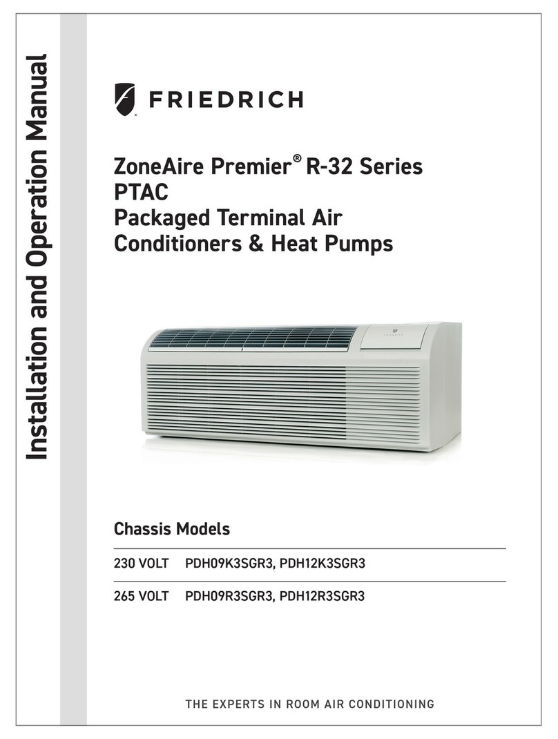
Friedrich FRESHAIRE PVH09K3FA Guide

1 PB
Service/ Parts Manual
PTAC
FRESHAIRE®
Standard Chassis Models
PVH12K3FA, PVH12K3FB, PVH12R3FA, PVH12R3FB
9K
12K
94131400_01
PVH09K3FA, PVH09K3FB, PVH09R3FA, PVH09R3FB

2 PB
INTRODUCTION 4
Important Safety Information 4
Personal Injury Or Death Hazards 5
Operation of Equipment in During Construction 7
Typical Unit Components and Dimensions 7
Model Number Reference Guide 8
Serial Number Reference Guide 9
Product Features 10
SPECIFICATIONS 12
General Specications 9-12k Heat Pump Models 12
Electrical Data 14
OPERATION 17
Function and Control 17
Buttons and Display 17
Temperature Denition 17
System Basic Function 17
1) Cooling Mode 17
2) Heating Mode 17
3) Room Freeze Protection (AUTO HEATING) 18
4) Temperature Sensor Open Circuit or Short Circuit Protection 18
5) Power cut protection 18
6) Compressor and DC-inverter features 18
7) Smart fresh air system 19
Advanced Functions 21
Advanced Settings 21
Memory Function 22
FD Control (front-desk control) & 24V REMOTE THERMOSTAT 22
Protection Functions 23
System Conguration Fresh Air Vent Control 25
Digital Control User Input Conguration 28
Settings- Detailed Congurations 29
Refrigeration Sequence Of Operation 30
Refrigerant System Diagram 31
ROUTINE MAINTENANCE 32
INSTALLATION 33
PTAC Installation Recommendations 33
Wall Sleeve Installation Instructions (PDXWS) 34
Alternate Wall Installations 35
PXDR10 Drain Kit Installation 38
External Drain 39
PXGA Standard Grille 40
Chassis Install 42
Remote Control Thermostat Installation 43
Front Desk Control Terminal 44
Final Inspection & Start-up Checklist 45
UNIT DISASSEMBLY AND COMPONENT REPLACEMENT 46
Remove Chassis 46
Remove User Interface 47
Open Electrical Control Box 48
Remove Main PCB (logic) Board 48
Remove Power Cord 49
Remove Power PCB 50
Remove IPM PCB (Inverter Board) 52
Remove Blower Wheel (Inside Fan) 53
Remove Blower Wheel Motor (Inside Fan) 56
Remove Heating Element 58
Remove Freshaire Components 59
Remove Outdoor Fan 61
Remove Reversing valve Solenoid 64
TABLE OF CONTENTS

3 PB
R-410A SEALED SYSTEM REPAIR 65
Refrigerant Charging 66
Undercharged Refrigerant Systems 67
Overcharged Refrigerant Systems 68
Restricted Refrigerant System 69
Sealed System Method of Charging/ Repairs 70
COMPONENT TESTING 71
Hermetic Components Check 71
Reversing Valve Description And Operation 72
Testing The Reversing Valve Solenoid Coil 73
Checking The Reversing Valve 74
Touch Test Chart : To Service Reversing Valves 76
Compressor Checks 77
Compressor Replacement 79
Compressor Replacement -Special Procedure in Case of Compressor Burnout 80
Check Indoor Fan Motor 81
Check Outdoor Fan Motor 81
Check Fan Motor Capacitors 82
Main PCB (logic) Board Connector Identication 83
Power PCB (Power Board) Connector Identication 84
TROUBLESHOOTING 85
Basic Troubleshooting 85
Error code and solutions 87
Unit Does Not Operate 89
Check Electric Heater Control 92
Check Thermistors 93
Check Thermistors -Resistance Table of Thermistors (5K) 94
Check Thermistors -Resistance Table of Thermistors (50K)(Compressor Discharge Sensor) 96
WIRING DIAGRAMS 98
PARTS CATALOG 99
PVH09K3FA, PVH09K3FB, PVH09R3FA, PVH09R3FB 100
PVH12K3FA, PVH12K3FB, PVH12R3FA, PVH12R3FB 100
ACCESSORIES 105
APPENDIX 107
Reference Sheet of Celsius and Fahrenheit 107
WARRANTY 108
FRIEDRICH AUTHORIZED PARTS DEPOTS 109
TABLE OF CONTENTS

4 PB
Your safety and the safety of others is very
important.
We have provided many important safety messages in this manual and on your appliance. Always read
and obey all safety messages.
This is a safety Alert symbol.
This symbol alerts you to potential hazards that can kill or hurt you and
others.
All safety messages will follow the safety alert symbol with the word
“WARNING”
or “CAUTION”. These words mean:
Indicates a hazard which, if not avoided, can result in severe personal
injury or death and damage to product or other property.
Indicates a hazard which, if not avoided, can result in personal injury and
damage to product or other property.
All safety messages will tell you what the potential hazard is, tell you
how to reduce the chance of injury, and tell you what will happen if the
instructions are not followed.
WARNING
Refrigeration system
under high pressure
Do not puncture, heat, expose to flame or
incinerate.
Only certified refrigeration technicians should
service this equipment.
R410A systems operate at higher pressures
than R22 equipment. Appropriate safe service
and handling practices must be used.
Only use gauge sets designed for use with
R410A.
Do not use standard R22 gauge sets.
NOTICE
CAUTION
WARNING
The information in this manual is intended for use by a qualied technician who is familiar with the safety proce-
dures required for installation and repair, and who is equipped with the proper tools and test instruments required
to service this product.
Installation or repairs made by unqualied persons can result in subjecting the unqualied person making such
repairs as well as the persons being served by the equipment to hazards resulting in injury or electrical shock
which can be serious or even fatal.
Safety warnings have been placed throughout this manual to alert you to potential hazards that may be encoun-
tered. If you install or perform service on equipment, it is your responsibility to read and obey these warnings to
guard against any bodily injury or property damage which may result to you or others.
Important Safety Information
INTRODUCTION

5 PB
SAFETY
FIRST
WARNING AVERTISSEMENT ADVERTENCIA
Do not remove, disable or
bypass this unit’s safety
devices. Doing so may
cause fire, Doing so may
cause fire, injuries, or
death.
Ne pas supprime, désactiver
ou contourner cette l´unité
des dispositifs de sécurité,
faire vous risqueriez de
provoquer le feu, les
blessures ou la mort.
No eliminar, desactivar o
pasar por alto los dispositi-
vos de seguridad de la
unidad. Si lo hace podría
producirse fuego, lesiones o
muerte.
ELECTRICAL HAZARDS:
• Unplug and/or disconnect all electrical power to the unit before performing inspections, maintenance, or service.
• Make sure to follow proper lockout/tag out procedures.
• Always work in the company of a qualied assistant if possible.
• Capacitors, even when disconnected from the electrical power source, retain an electrical charge potential
capable of causing electric shock or electrocution.
• Handle, discharge, and test capacitors according to safe, established, standards, and approved procedures.
• Extreme care, proper judgment, and safety procedures must be exercised if it becomes necessary to test or
troubleshoot equipment with the power on to the unit.
• Do not spray water on the air conditioning unit while the power is on.
• Electrical component malfunction caused by water could result in electric shock or other electrically unsafe
conditions when the power is restored and the unit is turned on, even after the exterior is dry.
• Use air conditioner on a single dedicated circuit within the specied amperage rating.
• Use on a properly grounded outlet only.
• Do not cut or modify the power supply cord or remove the ground prong of the plug.
• Never operate the unit on an extension cord.
• Follow all safety precautions and use proper and adequate protective safety aids such as: gloves, goggles,
clothing, properly insulated tools, and testing equipment etc.
• Failure to follow proper safety procedures and/or these warnings can result in serious injury or death.
INTRODUCTION
Personal Injury Or Death Hazards

6 PB
• REFRIGERATION SYSTEM REPAIR HAZARDS:
• Use approved standard refrigerant recovering procedures and equipment to relieve high pressure before open-
ing system for repair.
• Do not allow liquid refrigerant to contact skin. Direct contact with liquid refrigerant can result in minor to moder-
ate injury.
• Be extremely careful when using an oxy-acetylene torch. Direct contact with the torch’s ame or hot surfaces
can cause serious burns.
• Make certain to protect personal and surrounding property with re proof materials and have a re extinguisher
at hand while using a torch.
• Provide adequate ventilation to vent off toxic fumes, and work with a qualied assistant whenever possible.
• Always use a pressure regulator when using dry nitrogen to test the sealed refrigeration system for leaks, ush-
ing etc.
• MECHANICAL HAZARDS:
• Extreme care, proper judgment and all safety procedures must be followed when testing, troubleshooting, han-
dling, or working around unit with moving and/or rotating parts.
• Be careful when, handling and working around exposed edges and corners of the sleeve, chassis, and other unit
components especially the sharp ns of the indoor and outdoor coils.
• Use proper and adequate protective aids such as: gloves, clothing, safety glasses etc.
• Failure to follow proper safety procedures and/or these warnings can result in serious injury or death.
• PROPERTY DAMAGE HAZARDS
• FIRE DAMAGE HAZARDS:
• Read the Installation/Operation Manual for the air conditioning unit prior to operating.
• Use air conditioner on a single dedicated circuit within the specied amperage rating.
• Connect to a properly grounded outlet only.
• Do not remove ground prong of plug.
• Do not cut or modify the power supply cord.
• Do not use extension cords with the unit.
• Be extremely careful when using acetylene torch and protect surrounding property.
• Failure to follow these instructions can result in re and minor to serious property damage.
• WATER DAMAGE HAZARDS:
• Improper installation, maintenance or servicing of the air conditioner unit can result in water damage to personal
items or property.
• Insure that the unit has a sufcient pitch to the outside to allow water to drain from the unit.
• Do not drill holes in the bottom of the drain pan or the underside of the unit.
• Failure to follow these instructions can result in damage to the unit and/or minor to serious property damage.
INTRODUCTION
Personal Injury Or Death Hazards

7 PB
INTRODUCTION
Operation of Equipment in During Construction
• OPERATION OF EQUIPMENT MUST BE AVOIDED DURING CONSTRUCTION PHASES WHICH
WILL PRODUCE AIRBORNE DUST OR CONTAMINTES NEAR OR AROUND AIR INTAKE
OPENINGS:
• Wood or metal framing;
• Drywalling or sheathing,
• Spackling or applying joint compound.
• Sanding or grinding.
• Moulding or trimwork.
NOTICE
Operating the equipment during any phase of active construction noted above can void
the equipment’s warranty, also leading to poor performance and premature failure
Typical Unit Components and Dimensions
WALL SLEEVE
FILTERS
DISCHARGE GRILLE
RETURN AIR GRILLE
OUTDOOR GRILLE
PDXWS Wall Sleeve
Dimensions: 16" H x 42" W x
13-¾" D
Front Cover Dimensions:
16" H x 42" W x 7-¾" D
Cut-Out Dimensions:
16-¼"x42-¼"

8 PB
INTRODUCTION
IMPORTANT: It will be necessary for you to accurately identify the unit you are servicing, so you can be certain of a
proper diagnosis and repair.
Figure 103
This service manual is designed to be used in conjunction with the installation and operation manuals provided
with each air conditioning system.
This service manual was written to assist the professional service technician to quickly and accurately diagnose
and repair malfunctions.
Installation procedures are not given in this manual. They are given in the Installation and Operation Manual which
can be aquired on the Friedrich website (www.friedrich.com).
Model Number Reference Guide
VH09 3 F
MODEL NUMBER
Series
PV = Friedrich Digital PTAC
Nominal Capacity
Engineering Digit
System
E = Cooling with electric heat
H = Heat Pump with Auxiliary Heat
Design Series
Chassis
F= FreshAire
07 = 7,000 Btuh
09 = 9,000 Btuh
12 = 12,000 Btuh
15 = 15,000 Btuh Nominal Heater Size (230V or 265V)
3=3kW
Voltage
K = 230/208V - 1 Ph. - 60 Hz.
R = 265V - 1 Ph. - 60 Hz.
A

9 PB
INTRODUCTION
Serial Number Reference Guide
Figure 104
YEAR OF MANUFACTURE
17 = 2017 18 = 2018
19 = 2019 20 = 2020
21 = 2021 22 = 2022
MONTH OF MANUFACTURE
01 = JANUARY
02 = FEBRUARY
03 = MARCH
04 = APRIL
05 = MAY
06 = JUNE
07 = JULY
08 = AUGUST
09 = SEPTEMBER
10 = OCTOBER
11 = NOVEMBER
12 = DECEMBER
MANUFACTURING LOCATION
NUMERIC SEQUENCE
FIRST UNIT OF EACH MONTH = 00001
17 12 M 00001
Refer to the Chart below for Serial Numbers beginning with an Alpha Sequence
A K A M 00001
LJ = 2009 AE = 2015
AK = 2010 AF = 2016
AA = 2011 AG = 2017
AB = 2012
AC = 2013
AD = 2014
A = Jan D = Apr G = Jul K = Oct
E = May H = Aug L = NovB = Feb
C = Mar F = Jun J = Sep M = Dec
PTAC Serial Number Identification Guide
PRODUCT LINE
M = PRODUCT CODE
MONTH MANUFACTURED
SERIAL NUMBER
PRODUCTION RUN NUMBERYEAR MANUFACTURED

10 PB
INTRODUCTION
Product Features
19
Friedrich PTAC Digital Control and Unit Features
The new Friedrich digital PTAC has state of the art features to improve guest comfort, indoor air quality and conserve energy. Through the use of specifically
designed control software for the PTAC industry Friedrich has accomplished what other Manufacturer’s have only attempted – a quiet, dependable, affordable
and easy to use PTAC. Below is a list of features and their benifit to the owner.
ONLY TWO MODELS
BETTER
DEHUMIDIIFICATION
SOFT START
OPERATION
MERV 8 OUTDOOR AIR
FILTER
REMOTE THERMOSTAT
OPERATION
Some applications require the use of a wall-mounted thermostat. All new Friedrich PTACs may be
switched from unit control to remote thermostat control easily without the need to order a special model
or accessory kit.
INTERNAL DIAGNOSTIC
PROGRAM
The Friedrich digital PTAC features a self-diagnostic program that can alert maintenance to component
failures or operating problems. The internal diagnostic program saves properties valuable time when
diagnosing running problems.
ELECTRONIC
TEMPERATURE
LIMITING
By limiting the operating range, the property can save energy by eliminating “max cool” or “max heat” situ-
ations common with older uncontrolled systems. The new electronic control allows owners to set operat-
ing ranges for both heating and cooling independently of one another.
ROOM FREEZE
PROTECTION
When the PTAC senses that the indoor room temperature has fallen to 50°F, the unit will cycle on the
fan (high) and the electric strip heat to raise the room temperature to 55°F, and then cycle off again. This
feature works regardless of the mode selected and can be turned off.
CONDENSATE REMOVAL
SYSTEM
Condenser fan utilizes slinger ring technology to pick up condensate from the base pan and disperse it on
to the condenser coil where it evaporates. This helps to cool the coil and increase the energy efciency
of the unit.
DC INVERTER FreshAire PTACs utilize a DC inverter rotary compressor to ensure part load efficiencies and reliable
operation.
UNIVERSAL ELECTRIC
HEATER
Unit has a universal power cord with 20 Amp coming standard out of the box.
All units are factory run tested to ensure trouble free operation.
FACTORY RUN-TEST

11 PB
INTRODUCTION
Product Features
20
DIGITAL DEFROST
THERMOSTAT
The PV-Series uses a digital thermostat to accurately monitor the outdoor coil conditions to allow the heat
pump to run whenever conditions are correct. Running the PTAC in heat pump mode saves energy and
reduces operating costs. The digital thermostat allows maximization of heat pump run time.
INSTANT HEAT
HEAT PUMP MODE
Heat pump models will automatically run the electric heater to quickly bring the room up to temperature
when initially energized, then return to heat pump mode. This ensures that the room is brought up to
temperature quickly without the usual delay associated with heat pump units.
SEPARATE HEAT/COOL
FAN CYCLE
CONTROL
The owner may choose between fan cycling or fan continuous mode based on property preference. Fan
continuous mode is used to keep constant airflow circulation in the room during all times the unit is ‘ON’. Fan
cycle will conserve energy by only operating the fan while the compressor or electric heater is operating.
The
ability to set the fan cycling condition independently between heating and cooling mode will increase
user comfort by allowing the choice of only constantly circulating air in the summer or winter time (unlike
other PTAC brands that only allow one selection).
EMERGENCY
HEAT OVERRIDE
In the event of a compressor failure in heat pump mode, the compressor may be locked out to provide
heat through the resistance heater. This feature ensures that even in the unlikely event of a compressor
failure, the room temperature can be maintained until the compressor can be serviced.
CENTRAL DESK
CONTROL
READY(ONLY FOR UNIT
CONTROL)
All Friedrich digital PTACs have low voltage terminals ready to connect a central desk control energy
management system. Controlling the unit from a remote location like the front desk can reduce energy
usage and requires no additional accessories on the PTAC unit.
INDOOR COIL
FROST SENSOR
The frost sensor protects the compressor from damage in the event that airflow is reduced or low outdoor
temperatures cause the indoor coil to freeze. When the indoor coil reaches 33°F, the compressor is
disabled and the fan continues to operate based on demand. Once the coil temperature returns to 53°F,
the compressor returns to operation.
ULTRAQUIET
AIR SYSTEM
The PV-Series units feature an indoor fan system design that reduces sound levels without lowering
airow or preventing proper air circulation.
HIGH EFFICIENCY The Friedrich PTAC has been engineered so that all functional systems are optimized so that they work
together to deliver the highest possible performance.
DUAL MOTOR The dual-motor design means that the indoor motor can run at slower speeds which reduces sound
levels indoors.
ROTARY COMPRESSOR High efciency rotary compressors are used on all Friedrich PTACs to maximize durability and ef-
ciency.
TOP-MOUNTED
ANTIMICROBIAL
AIR FILTERS
All Friedrich PTAC return air filters feature an antimicrobial element that has proven to prevent mold and
bacterial growth in laboratory testing. PXFTB replacement filter kits feature the same antimicrobial agent.
All filters are washable, reusable and easily accessed from the top of the unit without the removal of the
front cover.
FILTERED FRESH
AIR INTAKE
Friedrich PTAC units are capable of introducing up to 40 CFM of outside air into the conditioned space.
The outdoor air passes through a washable mesh screen to prevent debris from entering the airstream.
Outdoor coil endplates made from aluminium reduce corrosion on the outdoor coil common with
other coil designs.
R-410A REFRIGERANT Friedrich PTAC units use environmentally-friendly refrigerant.
ALUMINIUM ENDPLATES
BREAK-PROOF
CONTROL DOOR
GALVANIZED ZINC
WALL SLEEVE AND
BASE PAN
Galvanized zinc coated steel wall sleeve and steel base pan undergo an 11-step preparation
process, are powder coated with a polyester finish and cured in an oven for exceptional durability.
Break-proof control door design maintains the integrity of the unit.

12 PB
SPECIFICATIONS
General Specications 9-12k Heat Pump Models
PVH Series Cooling with Heat Pumps
Model PVH09K PVH12K PVH09R PVH12R
PERFORMANCE DATA:
Cooling Capacity Btu 9600/9400 12000/11800 9600 12000
Cooling Capacity Min./Max Btu 6462-12099 7929-17142 6462-12099 7929-17142
Cooling Watts 790/775 1040/1025 800 1040
Energy Efciency Ratio EER 12.1/12.1 11.5/11.5 12.0 11.5
Reverse Heating Capacity Btu 8200/8500 11600/11800 8500 11800
Reverse Heating Capacity Min./Max. Btu 5606-11475 6995-16187 5606-11475 6995-16187
Heating Watts 710/685 970/950 710 970
COP 3.51/3.51 3.57/3.58 3.51 3.57
Moisture Removal Pts./Hr. 1.4 1.9 1.23 2.43
Sensible Heat Ratio 80% 78% 82.7% 73.7%
ELECTRICAL DATA:
Voltage (1 PHASE, 60 Hz) 230/208 230/208 265 265
Operational Voltage Range 253-187 253-187 292-239 292-239
Current Amps 4.4/4.5 4.5/5.0 3.8 4.7
Reverse Heat Amps 4.0/4.1 4.6/4.9 3.6 4.3
Power Factor 0.80 0.96 0.82 0.90
Compressor LRA N/A N/A N/A N/A
Compressor RLA 3.2 4.1 4.2 6.2
Outdoor Fan Motor HP 1/14 1/12 1/14 1/12
AIRFLOW DATA:
Indoor CFM, HIGH 400 470 400 470
Indoor CFM, LOW 250 360 290 360
PHYSICAL DATA:
Sleeve Dimensions H x W x D 16” x 42” x 13 3/4” (all models)
Dimensions with front H x W x D 16” x 42” x 21” (all models)
Cut Out Dimensions H x W 16 1/4”x 42 1/4” (all models)
Net Weight Lbs. 115 120 115 120
Shipping Weight Lbs. 137 142 137 142
R-410A Charge Oz. 30.34 32.80 32.1 32.8
Figure 202 (General Specs)

13 PB
SPECIFICATIONS
Figure 205 ( Chassis Specs)
Unit:inch
21 1/2
10
42
40
16
E
Figure 206 (Typical Unit Components and Dimensions)

14 PB
SPECIFICATIONS
Electrical Data
13
GNINRAW
15/20A LCDI Device 30A LCDI Device
TEST BEFORE EACH USE
NOTTUBTESERSSERP.1
2. PLUG LCDI INTO POWER
ELCATPECER
,NOTTUBTSETSSERP.3
RESET BUTTON SHOULD
POP UP
4. PRESS ,NOTTUBTSET
FOR USE
DO NOT TSETEVOBAFIESU
SLIAF
WHEN GREEN LIGHT IS ON
IT IS WORKING PROPERLY
RESET TEST
GNINRAW
TEST BEFORE EACH USE
NOTTUBTESERSSERP.1
2. PLUG LCDI INTO POWER
ELCATPECER
,NOTTUBTSETSSERP.3
RESET BUTTON SHOULD
POP UP
,NOTTUBTSETSSERP.4
FOR USE
DO NOT TSETEVOBAFIESU
SLIAF
WHEN GREEN LIGHT IS ON
IT IS WORKING PROPERLY
RESET
TEST
FRP014
A. Electrical Rating Tables
All 230/208 volt units are equipped with LCDI power cords.
All 265 volt units are equipped with non-LCDI power cords.
FUSE/CIRCUIT
BREAKER
Use ONLY type and size fuse or HACR cir-
cuit breaker indicated on unit’s rating plate.
Proper current protection to the unit is the
responsibility of the owner. NOTE: A time
delay fuse is provided with 265V units.
GROUNDING
Unit MUST be grounded from branch circuit
through service cord to unit, or through
separate ground wire provided on per-
manently connected units. Be sure that
branch circuit or general purpose outlet is
match plug on service cord and be within
reach of service cord. Refer to Table 1 for
proper receptacle and fuse type. Do NOT
alter the service cord or plug. Do NOT use
an extension cord.
RECEPTACLE
service cord and be within reach of service
cord. Refer to Table 1 for proper receptacle
and fuse type. Do NOT alter the service
cord or plug. Do NOT use an extension
cord.
All Friedrich 230/208V PTAC units are shipped from the factory with a
Leakage Current Detection Interrupter (LCDI) equipped power cord. The
LCDI device meets the UL and NEC requirements for cord connected air
conditioners effective August 2004.
To test your power supply cord:
1. Plug power supply cord into a grounded 3 prong outlet.
2. Press RESET.
3. Press TEST ( listen for click; Reset button trips and pops out).
4. Press and release RESET (listen for click; Reset button latches
and remains in). The power supply cord is ready for operation.
NOTE: The LCDI device is not intended to be used as a switch.
Once plugged in the unit will operate normally without the need to reset
the LCDI device.
If the LCDI device fails to trip when tested or if the power supply cord is
damaged it must be replaced with a new supply cord obtained from the
product manufacturer, and must not be repaired.
B. Power Cord Information (230/208V models only)
Figure 14
Typical LCDI Devices
NOTE: Use Copper Conductors ONLY. Wire sizes are per NEC, check local codes for overseas applications.
WARNING
Electrical Shock Hazard
Turn off electrical power before service
or installation.
ALL electrical connections and wiring
MUST be installed by a qualified
electrician and conform to the National
Code and all local codes which have
jurisdiction.
Failure to do so can result in property
damage, personal injury and/or death.
RECEPTACLES AND FUSE TYPES
Voltage 230V 265V
Amps 15 20 30 15 20 30
Heater Size 2.5 kW 3.5 kW 5.0 kW 2.5 kW 3.5 kW 5.0 kW
Receptacles
NEMA#
Receptacle6-15R 6-20R 6-30R 7-15R 7-20R 7-30R
NEMA#
Plug 6-15P 6-20P 6-30P 7-15P 7-20P 7-30P
Table 1

15 PB
SPECIFICATIONS
Electrical Data
14
Electrical Wiring for 265 Volt
Models
NOTE: It is recommended that the PXSB subbase assembly, the
PXCJA conduit kit (or equivalent) be installed on all hardwire
units. If installing a ush-oor mounted unit, make sure the
chassis can be removed from the sleeve for service and
maintenance.
WARNING
Electrical Shock Hazard
Turn off electrical power before service
or installation.
ALL electrical connections and wiring
MUST be installed by a qualified
electrician and conform to the National
Code and all local codes which have
jurisdiction.
Failure to do so can result in property
damage, personal injury and/or death.
Power Cord Installation
All 265V PTAC/PTHP units come with a factory installed non-LCDI
power cord for use in a subbase. If the unit is to be hard-wired refer to
the instructions below.
To install the line voltage power leads and con-
duit to chassis, follow the instructions below
and refer to Figures 25-27 on page 19. PXCJA
Conduit Kit is required with this setup.
1. Follow the removal process of the chassis’s junction box
(Figure 25).
2. Prepare the 265V (or 230V) power cord for connection to the chas-
sis’ power cord connector by cutting the cord to the appropriate
length (refer to Figure 26 and follow Figure 15). Power cord harness
selection shown on Table 2
Table 2
Model Heater kW Power Cord Kit Voltage Amperage Receptacle
PDE/PDH07K 2.5 PXPC23015A 230/208 15 NEMA 6-15r
3.5 PXPC23020A (STD) 230/208 20 NEAM 6-20r
PDE/PDH09K 2.5 PXPC23015A 230/208 15 NEMA 6-15r
3.5 PXPC23020A (STD) 230/208 20 NEMA 6-20r
5.0 PXPC23030 230/208 30 NEMA 6-30r
PDE/PDH12K 2.5 PXPC23015A 230/208 15 NEMA 6-15r
3.5 PXPC23020A(STD) 230/208 20 NEMA 6-20r
5.0 PXPC23030 230/208 30 NEMA 6-30r
PDE/PDH15K 2.5 PXPC23015A 230/208 15 NEMA 6-15r
3.5 PXPC23020A 230/208 20 NEMA 6-20r
5.0 PXPC23030 (STD) 230/208 30 NEMA 6-30r
PDE/PDH07R 2.5 PXPC26515A 265 15 NEMA 7-15r
3.5 PXPC23020A (STD) 265 20 NEMA 7-20r
PDE/PDH09R 2.5 PXPC26515 265 15 NEMA 7-15r
3.5 PXPC23020A (STD) 265 20 NEMA 7-20r
5.0 PXPC26530 265 30 NEMA 7-30r
PDE/PDH12R 2.5 PXPC26515A 265 15 NEMA 7-15r
3.5 PXPC23020A (STD) 265 20 NEMA 7-20r
5.0 PXPC26530 265 30 NEMA 7-30r
PDE/PDH15R 2.5 PXPC26515A 265 15 NEMA 7-15r
3.5 PXPC26520A 265 20 NEMA 7-0r
5.0 PXPC23030 (STD) 265 30 NEMA 7-30r
203/208 Electric Heater Rating (Conguration Based on Power Cord0
POWER CORD VOLTAGE BRANCH CKT AMPS MCA WATTS
PXPCFA23015A 230/208 15 13.9 2500
PXPCFA23020A 230/208 20 19.9 3600
PXPCFA23030A 230/208 30 27.5 5000
PXPCFA26515A 265V 15 12.0 2500
PXPCFA26515A1 265V 15 7.3 1500
PXPCFA26520 265V 20 16.8 3500
PXPCFA26530 265V 25 23.8 5000
TABLE 2
MODEL HEATER kW Power Cord Kit Voltage Amperage Receptacle
PVH09K 2.5(optional) STD 230/208 15 NEMA 6-15r
3.5(default) STD 230/208 20 NEMA 6-20r
PVH12K 1.5(optional) STD 230/208 15 NEMA 6-15r
3.5(default) STD 230/208 20 NEMA 6-20r
5.0(optional) STD 230/208 30 NEMA 6-30r
PVH09R 2.5(optional) STD 265/277 15 NEMA 7-15r
3.5(default) STD 265/277 20 NEMA 7-20r
PVH12R 1.5(optional) STD 265/277 15 NEMA 7-15r
3.5(default) STD 265/277 20 NEMA 7-20r
5.0(optional) STD 265/277 30 NEMA 7-30r

16 PB
SPECIFICATIONS
Electrical Data
15
3. Route the cut ends of harness through the conduit connector
assembly and flex conduit sleeve. Be sure to use the supplied
conduit bushing to prevent damage to the cord by the conduit.
The cord should pass through the Locknut, Spacer, Chassis
Junction Box, Conduit Connector, Bushing, then the Conduit
Sleeve. See Figure 17.
4. Route the cut ends of the power cord through the elbow connector
at the other end of the conduit. Tighten screws on elbow connector
to secure conduit sleeve.
5. Fasten and secure the elbow connector to the wall junction box
cover with locknut. Place and mount the wall junction box with
the four wall mounting screws making sure to pass the wall lines
through the junction box. Connect and join all wall lines with the
stripped ends using wire nuts. Tighten both screws of the wall
junction box cover to junction box.
6. Follow steps 4-6 and refer to Figure 27.
Figure 15 Figure 16
Figure 17
FRP032
4.0 IN.
18.0 IN.
TRIM HARNESS
TO LENGTH
STRIP WIRE ENDS (0.5 IN.)
TO WALL JUNCTION
TO CHASSIS JUNCTION
EXPOSE
WIRES
(1.0 IN.)
FRP033
GROUND
SCREW
GROUND
WIRE
HARNESS
JUNCTION
BOX
WALL CONNECTION
JUNCTION
BOX COVER
COVER
SCREWS
STRAIGHT
CONNECTOR
FRP034
LOCKNUT
SPACER
SPACER
BUSHING
LEADING SIDE FOR
WIRE HARNESS INSERTION
EXITING SIDE FOR
WIRE HARNESS
CHASSIS
JUNCTION
BOX
CONDUIT
CONNECTOR
CONDUIT
SLEEVE

17 PB
OPERATION
Function and Control
Buttons and Display
1) Buttons
There are ON/OFF, UP, DOWN, HEAT, COOL, CONSTANT FAN and fan speed of HIGH, LOW, AUTO buttons.
1. ON/OFF: Press to turn power on or off to the unit.
2. COOL, HEAT: choose the mode of operation
3. HIGH, LOW, AUTO: choose the fan speed.
4. UP, DOWN: Adjust the setting temperature , default: 60-90°F(16~32°F).
2) Dual 8 Digital Tube Displayer and LED
Two 8 digital tube and 7 LEDs (ON/OFF, HIGH, LOW, AUTO, HEAT, COOL, CONSTANT FAN)
1. Mode LED display: when the unit is running in a certain mode, the corresponding LED is lit up.
2. ON/OFF LED: at ON status, the LED is lit up.
3. CONSTANT FAN LED: when this function is enabled, the LED is lit up.
4. Fan speed LED: when the unit is running at HIGH, LOW or AUTO fan speed, the corresponding LED is
litup.
5. Dual 8 digital tube displayer: normally, it displays the indoor ambient temperature. When the UP/DOWN
button is pressed it displays the setting temperature. When some error occurs, it displays the ERROR
CODE.
Temperature Denition
Indoor setting temperature (Ts)
Indoor ambient temperature (T1)
Indoor coil temperature (T2)
Outdoor coil temperature (T3)
Outdoor ambient temperature (T4)
Compressor discharge temperature (T5)
Indoor outlet air temperature (T6)
System Basic Function
Once the compressor starts, the compressor won’t stop with the change of the indoor temperature. Once the
compressor stops, it can only start after a 3 mins delay. (The compressor can stop immediately at the time of
mode switchover, turning off the unit, adjusting setting temperature and turning off from a function error.)
Depending on the different ambient temperatures and setting temperatures, the compressor runs at different
frequencies to achieve the best energy savings and comfort. This is the advantage over traditional A/C compressors.
1) Cooling Mode
Working conditions and process for cooling:
When T1≥Ts+2°F(1°C), cooling turns on.
When T1≤Ts-2°F(1°C), cooling turns OFF.
When Ts- 2°F(1°C)<T1<Ts+ 2°F(1°C), the unit keeps previous running status.
Indoor fan control in cooling mode:
The indoor fan will run synchronously with cooling demand. During no demand period if the CONSTANT
FAN button is turned off, it will run for 30s and then turn off..When CONSTANT FAN is ON, it will always be
running.
Outdoor fan control in cooling mode:
The outdoor fan has two speeds, low and high. When T4 is above 80°F, the fan operates in high speed.
When T4 drops to 77°F the fan operates in low speed.
2) Heating Mode
Working conditions and process for heating:
When T1≤Ts -2°F(1°C), the unit is running in heating mode. The heat pump or electric heating will start
depending on the ambient temperature condition.
When T1≥Ts+ 4°F(2°C), the heating is turned OFF.

18 PB
OPERATION
Function and Control
When Ts-2°F(1°C) <T1<Ts+ 4°F(2°C), the unit keeps at the previous running status.
Electric heater does not work with heat pump at the same time.
When T4>44°F 7°C, unit will run heat pump all the time.
When 32°F < T4 < 44°F, unit will run in electric heating mode to meet the rst cycle demand. From the
second cycle on, heat pump will operate.
When T4≤32°F, the E-heater will operate exclusively.
During heat pump mode, once T3 freezes to 5°F, or any fault occurs, unit will switch over to electric heating
mode.
Outdoor fan control in heat pump mode:
When T4 is above 57°F, outdoor fan runs at low speed to lower the noise;
When T4 drops to 53°F, outdoor fan runs at high speed, in order to ensure the heating capacity.
Electric heating mode:
The unit is equipped with a universal E-heater, which contains two independent heating elements. The 9K BTU
unit incorporates a 2.5kW and a 1.0kW element. The 12K BTU unit incorporates a 3.5kW an s1.5kW element.
Power Cord Selection
Use the appropriate power cord for each heating configuration as shown in the table below.
Power Cord 15A 20A 30A
9K BTU Unit 2.5kW 3.5kW N/A
12k BTU Unit 1.5kW 3.5kW 5kW
Indoor fan control in heating mode:
The indoor fan will run synchronously with the heating demand. During no demand period, it will run for
30s(heat pump) or 1min(E-heating) after CONSTANT FAN button is turned off, then turns OFF. When
CONSTANT FAN is ON, it will always berunning.
Defrost
In heat pump mode, if the compressor runs continuously for over 30 minutes and T3< 26°F, or runs continuously
for 90 minutes and T3<32°Fthe unit will enter defrost stage. Indoor fan will shut down. After the defrosting cycle
is finished, the unit turns to E-heating for the first cycle to heat up quickly.
3) Room Freeze Protection (AUTO HEATING)
This is valid only in standby mode. The dual 8 digital tube displays “L0”.
Entry condition: #5 DIP SWITCH is set to ON to enable the indoor freeze protection and the main board
detects the indoor ambient temperature is lower than 50°F(10°C) for 3 consecutive minutes.
Quitting condition: When indoor ambient temperature rises to 55 °F(13°C), the heating will stop.
4) Temperature Sensor Open Circuit or Short Circuit Protection
If the temperature sensor has an open circuit or a short circuit, the ERROR CODE will display on the digital
tube. If the malfunction of the temperature sensor is detected for 30 seconds, the unit will turn off.
5) Power cut protection
After power cut recovery, unit will have a time delay of 2 to 4 minutes to restart E-heating. The DC-inverter
soft start compressor will restart after 3mins.
6) Compressor and DC-inverter features
The DC-inverter compressor has a high efciency rating and energy savings can be 30% to 80%. Opera
tion voltage range is 160VAC~270VAC, making the unit operation more stable under a wider voltage range
power input. With its soft start feature, power surges can be avoided, and also lower the noise level. With
out the frequent start-stop, room temperature will be more stable and more comfortable.
The high performance IPM contains a PFC module and under heavy loading PF can be up to 99%, thus
decreases EMI pollution to power supply system, and also decreasing power surges.
The compressor driver chip is high performance, making the compressor more stable and reliable.

19 PB
OPERATION
Function and Control
7) Smart fresh air system
The control logic as the below table1 and table2, the DIP switch is SW3 on the main board.
DIP switch SW3 function
Freshaire
System
"Engagement Method" Mode Description
Sw3 Dip Switch 1 ON/ OFF FA fan runs only when Dip
Switch is set to "ON"
FA fan NEVER RUNS when
Dip Switch is set to "OFF"
Sw3 Dip Switch 2 Cycle/ Con-
tinuous
FA fan cycles On/ Off with
the unit indoor fan when Dip
Switch 1 is set to "ON" & Dip
Switch 2 is se to "Cycle"
"FA fan runs continuously
when Dip Switch 1 is set to
""ON"" & Dip Switch 2 is set
to ""Continuous"""
Relationship Between Inputs and Outputs
INPUTS OUTPUT
FreshAire Mode "24V wall
Therm ostat"
In Demand No Demand
Enable Continuous "ID Fan
Speed Selec-
tion"
ID Fan Opera-
tion
"Fresh-Air Fan
Operation"
ID Fan Opera-
tion
"Fresh-Air Fan
Operation"
YES NO High High ON High ON
low low low
Auto Auto OFF OFF
YES High High High O N
low low low
Auto Auto low
NO NO High High OFF High OFF
low low low
Auto Auto OFF
YES High High High
low low low
Auto Auto OFF

20 PB
OPERATION
Function and Control
Relationship Between Inputs and Output by 24V Wall Thermostat
INPUTS OUTPUT
FreshAire Mode "24V wall
Thermostat"
In Demand No Demand
Enable Continuous "ID Fan
Speed Selec-
tion"
ID Fan Opera-
tion
"Fresh-Air Fan
Operation"
ID Fan Opera-
tion
"Fresh-Air Fan
Operation"
YES NO High High ON High ON
low low low
Auto Auto OFF OFF
YES High High High O N
low low low
Auto Auto low
NO NO High High OFF High OFF
low low low
Auto Auto OFF
YES High High High
low low low
Auto Auto OFF
Relationship Between Inputs and Output by 12V Wall Thermostat
INPUTS OUTPUT
FreshAire Mode "12V wall
Thermostat"
In Demand No Demand
Enable Continuous "ID Fan
Speed Selec-
tion"
ID Fan Opera-
tion
"Fresh-Air Fan
Operation"
ID Fan Opera-
tion
"Fresh-Air Fan
Operation"
YES NO High High ON High ON
low low low
Auto Low OFF OFF
YES High High High ON
low low low
Auto Low low
NO NO High High OFF High OFF
low low low
Auto Low OFF
YES High High High
low low low
Auto Low OFF
This manual suits for next models
7
Table of contents
Other Friedrich Temperature Controllers manuals
Popular Temperature Controllers manuals by other brands

Vulcan-Hart
Vulcan-Hart YK-D Series instruction manual

Honeywell
Honeywell TS300 Specifications

Johnson Controls
Johnson Controls A11D Installation Sheets Manual

Thermal Care
Thermal Care RA Series Installation & operation manual

Airwell
Airwell MS 1040 F manual

Linear Technology
Linear Technology LTC2997 Demo Manual

Wolf Steel
Wolf Steel Condo Pack Installation and operating instructions

Brewolution
Brewolution FERMINATOR M07-2 instruction manual

Sensaphone
Sensaphone FGD-0108 Quick installation guide

Crestron
Crestron SolarSync GLS-LCCT quick start

ero electronic
ero electronic ESR-AC user manual

Carrier
Carrier EQT1-4 user guide