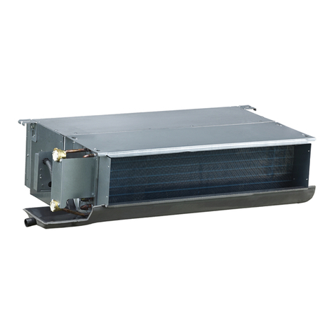
Frigicoll FMDA-130 User manual

MANUAL DE INSTALAÇÃO,
UTILIZAÇÃO E MANUTENÇÃO
Ventilador de condutas
FMDA-130
FHDA-130
FMDE-130
FHDE-130
FMDA-220
FHDA-220
FMDE-220
FHDE-220
FMDA-230
FHDA-230
FMDE-230
FHDE-230
FMDA-240
FHDA-240
FMDE-240
FHDE-240
FMDA-330
FHDA-330
FMDE-330
FHDE-330
FMDA-131
FHDA-131
FMDE-131
FHDE-131
FMDA-221
FHDA-221
FMDE-221
FHDE-221
FMDA-231
FHDA-231
FMDE-231
FHDE-231
FMDA-241
FHDA-241
FMDE-321
FHDE-241
FMDA-331
FHDA-331
FMDE-331
FHDE-331


Observações – Remarks
Para utilizar a unidade de forma correta e segura, o instalador, o utilizador e
o responsável pela manutenção, de acordo com as respetivas
competências, devem cumprir o que está indicado neste manual.
To use the unit correctly and safely, the installer, the user and the
maintenance man, for their respective competencies, must comply with what
is indicated in this manual.
■
Deve guardar-se este manual num local seco para evitar a sua deterioração, uma vez
que deve ser conservado durante, pelo menos, 10 anos para eventuais consultas
futuras.
■
Todas as informações contidas neste manual devem ser lidas e compreendidas
cuidadosamente, pois serão muito úteis tanto para uma instalação segura como para
uma utilização correta e operações de manutenção.
■
Deve prestar-se especial atenção às normas de funcionamento assinaladas com os
sinais “PERIGO” ou “AVISO”, pois o seu desrespeito pode provocar danos no aparelho
e/ou em pessoas ou objetos.
■
Para qualquer avaria não mencionada neste manual, deve contactar-se
imediatamente o Serviço Pós-Venda local.
■
Deve conservar-se este manual sempre com o aparelho.
■
Este manual é parte integrante e essencial do produto e deve ser entregue ao
utilizador.
■
Se a unidade for vendida ou transferida para outro proprietário, certifique-se de que o
manual permaneça com a unidade para ser utilizado pelo novo proprietário e/ou
instalador.
■
O fabricante declina toda a responsabilidade por quaisquer danos causados por
uma utilização incorreta do aparelho e por um conhecimento parcial ou
superficial das informações contidas neste manual.
■
Os dados técnicos, as características de estilo, os componentes e os acessórios
indicados neste manual não são vinculativos. O Fabricante reserva-se o direito de
efetuar, em qualquer altura, as alterações consideradas necessárias para melhorar o
produto.
■
As referências legais, normas ou regras técnicas mencionadas neste manual são
apresentadas a título meramente informativo e devem ser consideradas válidas a
partir da data de impressão deste manual. Se entrarem em vigor novos regulamentos
ou alterações às leis atuais, isso não obrigará o Fabricante de forma alguma em
relação a terceiros.
■
O Fabricante é responsável por garantir que o seu produto esteja em conformidade
com as leis, as diretivas e as normas de construção em vigor no momento em que o
produto é vendido. O conhecimento e o cumprimento dos regulamentos e das normas
legais relativos à conceção, instalação, funcionamento e manutenção das instalações
são da exclusiva responsabilidade, pelas respetivas competências, do projetista, do
instalador e do utilizador.
■
AVISO! É importante verificar se a conceção e a instalação estão em conformidade
com as normas atuais.
§
■
Store this manual in a dry location to avoid deterioration, as they must be kept for at
least 10 years for any future reference.
■
All the information in this manual must be carefully read and understood: as they’ll be
all very useful for both safe installation and proper use & maintenance operations.
■
Pay particular attention to the operating norms marked with “DANGER” or “WARNING”
signals as their disrepect can cause damage to the unit and/or person or objects.
■
For any malfunctions not mentioned in this manual, contact the local After sales Service
immediately.
■
Always keep this handbook with the unit.
■
This manual is an integral and essential part of the product and must be given to the
user.
■
Should the unit be sold or transferred to another owner, please ensure that the manual
remains with the unit for use by the new owner and/or installer.
■
The Manufacturer declines all responsibility for any damage whatsoever caused
by improper use of the unit, and a partial or superficial acquaintance with the
information contained in this manual.
■
The technical data, styling characteristics, components and accessories reported in
this manual are not binding. The Manufacturer reserves the right to make changes, at
any time, that are considered necessary to improve the product.
■
The lawful references, standards or technical rules mentioned in this manual are
presented merely for the sake of information and should be considered valid as of the
date this manual is printed. If new regulations or amendments to current laws go into
effect, this will not obligate the Manufacturer in any way with regard to others.
■
The Manufacturer is responsible for ensuring that its product conforms to the laws,
directives and construction standards in force at the time the product is sold. Knowledge
and compliance with legal regulations and standards regarding plant design,
installation, operation and maintenance are the exclusive responsibility, for the
respective competencies, of the designer, installer and user.
■
WARNING! It is important to verify that the design and installation conform with current
standards.
Cada unidade é fornecida com o seu esquema elétrico unívoco
específico.
REFIRA-SE APENAS AO MESMO ESTRITAMENTE!
Each unit is supplied with its specific univocal wiring diagram.
STRICTLY REFERE TO IT ONLY!
DADOS TÉCNICOS E ABSORÇÃO ELÉTRICA:
Consulte os valores/dados mencionados na etiqueta da
unidade
TECHNICAL DATA AND ELECTRICAL ABSORPTION:
Refer to values/data as mentioned on the unit’s label
Declaração de Conformidade – Conformity Declaration (DCF-0901-41021080-R00)
Declaramos, sob a nossa responsabilidade, que o equipamento acima referido é:
■
Unidade para aquecimento, condicionamento, ventilação e tratamento de ar em
ambientes civis, residenciais, comerciais e industriais, com a marca CE em
conformidade com as diretivas de segurança europeias e internacionais.
■
A unidade está em conformidade com:
-
Diretiva 2006/42/CE relativa a máquinas (ex 98/37/CE; ex 89/392/CEE e
alterações 91/368/CEE - 93/44/CEE - 93/68/CEE)
-
Diretiva 2006/95/CE relativa à baixa tensão (ex 73/23/CEE)
-
Diretiva 2004/108/CE relativa à compatibilidade eletromagnética (ex.
EMC/89/336/CEE)
-
97/23/CEE ver art. 3.3 ou art. 1.3.6 Diretiva relativa aos equipamentos sob
pressão (PED)
■
Unidade fabricada e testada de acordo com as seguintes diretivas: 92/31/CEE -
92/59/CEE e as seguintes normas: EN/292/1 - EN/292/2 - EN/294 - EN/55014/1 (+A1)
(+A2) - EN/55014/2 (+A1) (+A2) - EN/61000/3/2 (+A1) (+A2) - EN/61000/3/3 -
EN/60555/2 - EN/60204/1 - EN/62233 - EN/60335/1 (+A1) (+A11) (+A12) (+A13)
(+A14) (+A15) - EN/60335/2/40 (+A11) (+A12) (+A1) (+A2) (+A13) e alterações
conexas.
Gestão geral
We declare under own responsability that the above equipment complies is:
■
Unit for heating, conditioning, ventilation and air treatment in civil, residential,
commercial and industrial environments, CE branded in accordance with European and
International security directives.
■
The unit is in accordance with:
-
2006/42/CE Machine Directive (ex 98/37/CE ; ex 89/392/CEE and
amandments 91/368/CEE - 93/44/CEE - 93/68/CEE)
-
2006/95/CE Low Voltage Directive (ex 73/23/CEE)
-
2004/108/CE Electromagnetic Compatibility Directive (ex. EMC/89/336/CEE)
-
97/23/CEE see Art.3.3 or Art.1.3.6 Pressure Equipment Directive (PED)
■
Unit manufactured and tested according to the following to the following Directives:
92/31/CEE – 92/59/CEE and the following Standards Standards: EN/292/1 – EN/292/2
– EN/294 – EN/55014/1 (+A1) (+A2) – EN/55014/2 (+A1) (+A2) – EN/61000/3/2 (+A1)
(+A2) – EN/61000/3/3 – EN/60555/2 – EN/60204/1 – EN/62233 – EN/60335/1 (+A1)
(+A11) (+A12) (+A13) (+A14) (+A15) – EN/60335/2/40 (+A11) (+A12) (+A1) (+A2)
(+A13) and related amendments.
General Management

Símbolos de segurança – Safety symbols
Pág. 02
ATENÇÃO
Perigo!!!
PERIGO:
Fonte de
alimentação
PERIGO:
Desligar a linha de
alimentação
PERIGO:
Temperatura alta
PERIGO:
Peças móveis
ATTENTION
Danger !!!
DANGER:
Power Supply
DANGER:
Disconnect Power Line
DANGER:
Hight Temperature
DANGER:
Moving parts
OBRIGATÓRIO:
Ligação à terra
OBRIGATÓRIO:
Utilizar o empilhador
OBRIGATÓRIO:
Utilizar luvas de proteção
OBRIGATÓRIO:
Apenas pessoal
qualificado
PROIBIDO
COMPULSORY:
Earthing
COMPULSORY:
Use undercarriage
COMPULSORY:
Use protective gloves
COMPULSORY:
Only Qualified Personnel
FORBIDDEN
Medidas de segurança – Safety measures
Respeite os seguintes regulamentos ao
INSTALAR, PÔR EM FUNCIONAMENTO, UTILIZAR
E REALIZAR A MANUTENÇÃO das unidades.
Observe the following regulations when
INSTALLING, STARTING UP, USING AND
SERVICING the units.
■
A instalação deve ser efetuada respeitando sempre rigorosamente as normas em
vigor no país onde o aparelho vai ser utilizado e seguindo, evidentemente, as
instruções dadas pelo fabricante. Apenas técnicos qualificados e os Centros de
Assistência Autorizados poderão efetuar a instalação.
■
As operações de instalação e manutenção da unidade só podem ser efetuadas
por pessoal qualificado e formado.
■
Os técnicos de assistência qualificados são os que possuem experiência técnica
específica no domínio da instalação de unidades de aquecimento e arrefecimento
para uso doméstico, de acordo com o Registo CORGI. Em qualquer caso, se
telefonar para o escritório do fabricante poderá receber todas as informações.
■
Installation is to be carried out always strictly complying with the current
standards of the country where the appliance is going to be used and following,
of course, the instructions given by the maker. Only skilled operators and
Authorized Assistance Centers will be entitled to carry out installation.
■
The installation and maintenance operations of the unit can be carried out by
qualified and trained personnel only.
■
Qualified service engineers are those having specific technical experience in
the field of heating and cooling installation unit for home use according to
CORGI Register. In any case, telephone in Manufacturer office and you can
receive all informations.
■
De acordo com o projeto de instalação, instalar as linhas de água refrigerada, as
linhas de água quente e as linhas de energia elétrica.
■
Certifique-se sempre de que a unidade e todas as suas partes elétricas foram
corretamente ligadas à terra antes de pôr a unidade em funcionamento.
■
According to the installation project, install the chilled water lines, the hot water
lines and the electric power lines.
■
Always make sure that the unit and all its electrical parts have been correctly
earthed prior to starting up the unit.
■
Se tiver de desmontar o aparelho, utilize luvas de proteção especiais.
■
Cuidado com as arestas afiadas no interior da unidade
■
Cuidado com os cantos dos telhados das unidades exteriores
■
Mantenha as grelhas de aspiração limpas.
■
Nunca utilize a unidade para suportar outro equipamento.
■
Nunca deixe ferramentas, peças sobressalentes, etc., no interior do aparelho.
■
Certifique-se de que todos os painéis de inspeção estão devidamente fechados.
■
Não exponha o aparelho a gases inflamáveis.
■
If you have to disassemble the unit, use special protective gloves.
■
Beware of sharp edges inside the unit
■
Beware of roof corners of outdoor units
■
Keep suction grids clear.
■
Never use the unit to support other equipment.
■
Never leave tools, spare parts, etc. inside the unit.
■
Make sure that all inspection panels are closed properly.
■
Do no expose the unit to inflammable gases.
■
Certifique-se de que a válvula de entrada de água está fechada.
■
O permutador arrefeceu.
■
Be sure that the inlet water valve is closed
■
The exchange device has cooled down.
■
Na unidade com ventiladores acessíveis (versões ocultas), não ligue a unidade
se a própria unidade não estiver fechada num espaço acessível apenas com a
utilização de ferramentas adequadas.
■
Os ventiladores podem atingir uma velocidade de 1000 rpm. Não introduza
qualquer objeto nem as mãos no ventilador elétrico.
■
In the unit with accessible fans (concealed versions), don’t start the unit if the
unit itself is not closed inside a space accessible only with the use of proper
tools.
■
Fans can reach a speed of 1000 rpm. Do not insert any object nor hands in the
electric fan.
■
Recomendamos a instalação de um interrutor de segurança que possa ser
facilmente alcançado para cortar a corrente, perto da unidade. Antes de qualquer
operação de limpeza e manutenção, corte a alimentação elétrica da unidade.
■
Antes de abrir a unidade, certifique-se de que todas as partes elétricas foram
desligadas. Em particular, certifique-se de que o ventilador está desligado e não
pode ser ligado inadvertidamente antes de abrir os painéis de inspeção.
■
VERIFIQUE A LIGAÇÃO À TERRA!!
■
We recommend to install a safety switch which can be easily reached to cut off
the current, near the unit. Before any cleaning and servicing operation, cut off
the power line to the unit.
■
Before opening the unit, make sure that all electrical parts have been switched
off. In particular, make sure that the tan is off and cannot be inadvertently started
prior to opening inspection panels.
■
CHECK THE EARTHING !!
■
Esta unidade foi concebida para ser utilizada apenas para fins de aquecimento e
arrefecimento. Qualquer utilização diferente não é permitida, pois pode ser
perigosa.
■
Se o aparelho funcionar numa casa onde vivam pessoas deficientes e/ou
crianças, deve ser colocado de forma segura e fora do seu alcance. Certifique-se
sempre de que a porta de acesso ao painel de controlo interno fica trancada.
■
Uma instalação incorreta pode causar danos a pessoas, animais e bens. Em caso
de instalação incorreta, o fabricante não pode ser responsabilizado por tais danos.
■
O fabricante não pode ser responsabilizado por tais danos causados por
utilizações incorretas, erradas, etc.
■
This unit is designed to be used for heating-cooling purposes only. Any different
use is not allowed as it may be dangerous.
■
Should the unit work in a house where disabled people and/or children live, it
must be placed safely away from their reach. Always make sure that the access
door to the inside control board stay locked.
■
An incorrect installation can cause damages to people, animals and property.
In case of erroneous installation, the manufacturer cannot be held responsible
for such damages.
■
The manufacturer cannot be held responsible for such damages by improrer
uses, errate uses, etc.
■
Em caso de avaria ou falha: desligue o aparelho, não tente repará-lo sozinho e
contacte o técnico.
■
Se vai deixar o gerador desligado durante muito tempo, certifique-se primeiro de
que este não pode, de forma alguma, causar danos a alguém.
■
In case of breakdown or failure: turn unit off, do not try to repair it on your own,
call operator.
■
If you are going to leave the generator off for a long time, first make sure that in
no way this could cause harm to anyone in any way.
Não se esqueça de que a garantia não pode ser aplicada em caso de modificações elétricas, mecânicas e outras modificações gerais!!
Please do not forget that warranty cannot be applied in case of electric, mechanical and other general modifications!!

Principais componentes – Main components
Pág. 03
Versões disponíveis em aço
galvanizado e versões em aço pré-
pintado
Available versions made of galvanized
steel and versions made of pre-painted
steel
13
De série – Standard
1
Estrutura de suporte em chapa de aço de grande espessura com orifícios para fixação à parede/teto + Isolamento térmico-acústico interior (classe M1)
Bearing structure made of large thickness sheet-steel with holes for fixing to wall/ceiling + Thermal-acoustic internal insulation (class M1)
2
Ventilador centrífugo de dupla entrada de ar (alhetas curvadas para a frente) - Double air inlet centrifugal fan (forward curved fins)
3
Motor elétrico de 3 velocidades 230 V-1 Ph-50 Hz diretamente acoplado ao ventilador – 3 speed electric motor 230V-1Ph-50Hz directly coupled to the fan
4
Serpentina (1 serpentina para uma unidade de sistema de 2 tubos) - Coil (1 coil for a 2-pipe system unit)
5
Ligações da serpentina de água - Water coil connections
6
Válvula de purga de ar manual - Manual air vent valve
7
Válvula manual de drenagem de água - Manual water drain valve
8
Tabuleiro de drenagem com tubos de drenagem + isolamento térmico
Drain pan with drain pipes + thermal insulation
9
Tubo de drenagem – Drain pipe
10
Placa de terminais elétricos – Electrical terminal board
Acessórios
11
Diferentes tipos de secções de filtro de ar (eficiência de filtragem G3, Classe M1)
e grelhas
Different types of air filter sections (filtering efficiency G3, Class M1) and grills
12
Sensor do termóstato de baixa temperatura da água
Water low temperature thermostat sensor
13
Diferentes tipos de secções de aquecimento (com aquecedores
elétricos ou com serpentina de água 3R, 1R, etc.) e plenum
Different types of heating sections (with electrical heaters or with
water coil 3R, 1R, etc.) and plenum
Embalagem – Packing
As unidades são enviadas com caixas de cartão
em palete como embalagem padrão; os
acessórios são fornecidos soltos em embalagens
separadas ou montados na unidade (a pedido).
Units are shipped with carton boxes on pallet as
standard packing; accessories are supplied loose
in packed separately or supplied mounted in the
unit (on request).
Transporte, receção, manuseamento – Transport, Receipt, Handling
■
O transporte deve ser efetuado de acordo com as indicações seguintes:
è As embalagens devem ser fixadas de forma segura no chão dos camiões.
è As embalagens devem ser cobertas.
■
A unidade possui uma embalagem de segurança especial para transporte e entrega, que deve
ser mantida em boas condições até que a unidade seja colocada no local de instalação.
■
Certifique-se de que a unidade possui todas as peças, conforme especificado na encomenda.
■
Verifique se existem danos e se a abreviatura da unidade é igual à do modelo encomendado.
■
Todas as unidades são testadas na fábrica antes do envio, pelo que, se houver danos, deve
comunicá-los imediatamente à transportadora.
■
A expedição, a descarga e o manuseamento das mercadorias são operações que devem ser
efetuadas com muito cuidado para não danificar as mercadorias. Tente não utilizar os
componentes da unidade como apoios para as mãos.
■
Ao levantar, deve ter-se em conta que o centro de gravidade da unidade pode estar
descentrado.
■
The transport must be done according to the following indications:
è Packages must be securely fixed at trucks floor.
è Packages must be covered.
■
The unit has a special safety packing for transport and delivery which must be kept in good
conditions till the unit is positioned on the installation place.
■
Make sure that the unit has all its parts, as specified in the order.
■
Check if there are any damages and if the unit abbreviation is the same as the one of the
ordered model.
■
Every unit is factory tested before shipment, therefore, if there are damages, report them
immediately to the carrier.
■
Shipping, unloading and handling of the goods are all operations to be carried out very carefully
in order not to damage goods. Try not to use the unit’s components as handholds.
■
When lifting, bear in mind that the centre of gravity of the unit may be off-centre.
NÃO MOLHAR
DO NOT WET
NÃO CALCAR
DO NOT TRAMPLE
NÃO DEIXAR EMBALAGENS SOLTAS DURANTE O
TRANSPORTE
DO NOT LEAVE LOOSE PACKAGES DURING THE
TRANSPORT
NÃO MANUSEAR A UNIDADE SOZINHO SE O
SEU PESO FOR SUPERIOR A 35 kg
DO NOT HANDLE THE UNIT ALONE IF ITS
WEIGHT IS OVER 35 kg
5

Armazenamento no local - Stocking at site
Pág. 04
3 tamanhos
disponíveis
845 1245 1645
A elevação deve ser
efetuada com dispositivos
mecânicos devido ao peso
da unidade.
The lifting should be done
with mechanical devices
because of the weight of the
unit.
As unidades devem ser armazenadas no interior do edifício!
The units must be stocked inside the building!
Instalação: Localização da unidade – Installation: Unit location
A INSTALAÇÃO DEVE ESTAR SEMPRE EM CONFORMIDADE COM A LEGISLAÇÃO LOCAL EM VIGOR
§ Verifique se a unidade e as suas características técnicas correspondem ao indicado no
projeto ou noutros documentos.
§ Mantenha sempre as peças da embalagem fora do alcance das crianças, pois podem ser
perigosas.
§ Antes da instalação da unidade, use vestuário de proteção adequado. Utilize equipamentos
e ferramentas adequados para evitar qualquer acidente de instalação.
§ Antes da instalação da unidade, recomenda-se a montagem na unidade dos eventuais
acessórios de separação, seguindo as instruções de montagem contidas em cada kit
individual.
§ Decida a posição de instalação. Coloque a unidade numa estrutura sólida que não provoque
vibrações e que seja capaz de suportar o peso da máquina.
THE INSTALLATION MUST BE ALWAYS COMPLIANT WITH THE CURRENT LOCAL LAWS
§ Check that the unit and its technical characteristics match what is indicated by the design or
other documents.
§ Always keep packing parts away from children reach, as they may be harmful.
§ Before the unit installation, please wear suitable protective clothes. Use suitable equipments
and tools to avoid any installation accident.
§ Before the unit installation we recommand to muont on the unit the eventual separating
optionals by following the assembly instructions contained in each single kit.
§ Decide the installation position. Locate the unit on a solid structure which does not cause
vibrations and is able to support the machine weight.
Versões para instalação encastrada:
O instalador deve tomar as medidas necessárias para disfarçar a unidade com painéis
adequados (tetos falsos, paredes falsas, painéis, etc.) que servem também de PROTEÇÃO
FIXA. Os painéis de proteção têm de ser firmemente fixados (apenas com ferramentas) para
evitar o contacto com peças perigosas (2006/42/CE), tais como arestas afiadas, peças elétricas,
ventiladores em funcionamento, etc., mas facilmente removíveis para permitir o acesso total à
unidade (manutenção extraordinária).
Versions for concealed installation:
The installer has to take the necessary steps to disguise it with appropriate panels (false ceilings,
false walls, panels, ect.) which also serve as FIXED PROTECTION. The protection panels have
to be firmly fixed (only by tools) to prevent contact with dangerous parts (2006/42/CE) like sharp
edges, electric parts, runnging fans, ect. but easily removable to allow total access to the unit
(extraordinary maintenance).
§ Através dos 4 orifícios de fixação da
estrutura de suporte, marque a
posição das cavilhas de expansão de
suporte.
§ Faça os furos para as cavilhas.
§ Instale a unidade com parafusos de expansão n.º 4 8 MA ou de haste roscada φ8 mm.
§ A unidade deve ser instalada de modo a não comprometer a entrada e o fornecimento de ar.
§ Mark through the 4 bearing structure fixing holes, the position of the holding expansion dowels.
§ Make the holes for the dowels.
§ Install the unit with no. 4 expansion screws 8 MA or threaded rod φ8 mm.
§ The unit must be installed so that the air intake and supply are not jeopardized.
Instalação: Áreas de manutenção – Installation: Areas for maintenance
A unidade tem de ser instalada de modo a permitir a manutenção normal e a
manutenção especial!
§ O teto falso, se existir, deve ser adequado para a remoção do painel inferior da unidade para
a inspeção do filtro e dos ventiladores.
§ No lado da ligação de água da unidade, deixe no mínimo 400 mm para a instalação de tubos
e válvulas.
The unit has to be installed in order to allow ordinary maintenance and
special maintenance!
§ The counter ceiling, if existing, must be suitable for the removal of the bottom panel of the
unit for the inspection of filter and fans.
§ At water connection side of unit leave at minimum 400 mm for pipes and valves installation
MÍN.
550 mm
MÍN.
400 mm
Lado da ligação de água
Water connection side
MÍN.
200 mm
MÍN.
550 mm

Instalação: Ligações de abastecimento de água – Installation: Water supply connections
Pág. 05
Atenção: Utilize sempre uma chave e dê uma segunda volta para ligar a
serpentina aos tubos.
§ Efetue as ligações hidráulicas.
§ Instale válvulas de fecho (MIN 3/4") para isolar a serpentina do resto do circuito em caso de manutenção especial.
Ligue a entrada de água com uma válvula de fecho e a saída com uma válvula de equilíbrio (ou instale 2 válvulas
de fecho).
§ Instale uma válvula de ventilação em cima e uma válvula de descarga de água em baixo.
§ As serpentinas de água são testadas a uma pressão de 30 bar e, por conseguinte, podem funcionar a uma
pressão máxima de 15 bar.
§ Posicione e apoie os tubos no exterior da unidade com suportes para aliviar o peso excessivo da serpentina.
Instale dispositivos anticongelantes. Se a unidade estiver instalada em compartimentos particularmente frios,
encha o depósito de água durante longos períodos de paragem.
Attention: Always use a key and second turn to connect the coil to the
pipes.
§ Make hydraulic connections.
§ Install shut-off valves (MIN 3/4") to isolate the coil from the rest of the circuit in the event of special maintenance.
Connect the inlet water with a shut off valve and the outlet with a balancing valve (or installed 2 shut off valves).
§ Fit a air-vent valve above and a water-discharge valve below.
§ The water coils are tested at a pressure of 30 Bar and therefore they can operate at a maximum pressure of 15
Bar.
§ Position and support tubes on unit exterior by brackets to relieve the coil of excessive weight.
Install antifreeze devices. If the unit is installed in particularly cold rooms, fill out the water tank during long rest
periods.
As ligações hidráulicas têm de ser efetuadas com tubos de diâmetro superior (limite mínimo igual) às ligações hidráulicas da unidade!
The hydraulic connections have to be realized with pipes with higher diameter (minimum limit equal) of the unit’s hydraulic connections!
Instalação: Tubo de drenagem – Installation: Drain pipe
■
Isole adequadamente os tubos de água para evitar pingos no modo de arrefecimento.
■
Instale um sistema de drenagem de condensado de dimensão adequada e coloque-o de modo a
favorecer a descarga (inclinação mínima de 3%) e não deve ter partes ascendentes ou
estrangulamentos para permitir um fluxo descendente regular.
■
Instale um sifão no sistema de drenagem de condensado.
■
O tubo de drenagem será ligado a uma rede pluvial de descarga.
■
Não utilize um esgoto de água branca ou preta (rede de esgotos) para evitar o retorno de odores
desagradáveis à divisão em caso de evaporação da água contida no sifão.
■
Appropriatly insulate water pipes to prevent dripping in cooling mode.
■
Install an appropriate size condensate drainage system and place it to favour the discharge (min
3% slope) and must not have rising parts or stranglings in order to allow a regular downflow.
■
Install a siphon in condensate drainage system.
■
The drain pipe will be connected to an unloading rain network.
■
Do not use white or black water (sewage system) to prevent unpleasant odour return into the
room in case of evaporation of the water contained in the siphon.
Quando os trabalhos estiverem concluídos, verifique o escoamento
regular da condensação, deitando água no tabuleiro.
When the works are finished check the regular discharge of the
condensation by pouring water on the pan.
O sistema de drenagem deve possuir um sifão de tamanho adequado para:
■
Assegurar a drenagem livre do condensado.
■
Impedir a entrada inadvertida de ar no circuito sob pressão negativa.
■
Evitar a fuga inadvertida de ar do circuito pressurizado.
■
Impedir a entrada de odores desagradáveis e de insetos.
NOTA: O sifão deve ter um tampão para facilitar a limpeza da secção inferior e ser fácil de
desmontar.
Siga as indicações abaixo para a instalação do sifão.
The drainage system should feature an adequately sized siphon to:
■
Ensure free condensate drainage.
■
Prevent the inadvertent entry of air into the circuit under negative pressure.
■
Prevent the inadvertent leakage of air from the pressurised circuit.
■
Prevent the entry of unpleasant odours and insects.
NOTE: The siphon should have a plug to facilitate cleaning of the lower section, and be easy to
disassemble.
Follow the indications below for design the siphon.
Tubo de drenagem da unidade
Unit’s drain pipe
φφ30 mm
Tubo - Pipe
MIN φφ30 mm
Tabuleiro de drenagem - Drain pan
Pressão negativa
Negative pressure
H1 (mm) = P + 30 min
H2 (mm) = H1 = P + 30 min
H3 (mm) = H1 + H2 = 2P + 60 min
Em que P é a pressão expressa em mm de calibre de água
(1 mm c.a. = 9.81 Pa)
Where P is pressure expressed in mm of water gauge (1 mm
c.a. = 9.81 Pa)
P =
Pressão negativa
Negative Pressure
P =
Pressão positiva
Positive Pressure
Tabuleiro de drenagem - Drain pan
Pressão negativa
Negative pressure
H1 (mm) = 20 min
H2 (mm) = P + 30 min
H3 (mm) = H1 + H2 = P + 50 min
Em que P é a pressão expressa em mm de calibre de água
(1 mm c.a. = 9.81 Pa)
Where P is pressure expressed in mm of water gauge (1 mm
c.a. = 9.81 Pa)
Tubos – Pipes
MÍN. φ
Ligações de água da unidade
φφ 3/4" Gás fêmea
Unit’s water connections
φφ3/4” Female gas

Instalação: Ligações elétricas – Installation: Electrical connections
Pág. 06
UNIDADE FABRICADA DE ACORDO COM A NORMA 2006/95/CE (EX 73/23/CEE)
UNIT MANUFACTURED ACCORDING WITH 2006/95/CE STANDARD (EX 73/23/CEE)
■
CUIDADO: certifique-se de que a alimentação elétrica da unidade está
desligada antes de efetuar qualquer ligação elétrica.
■
ATENÇÃO: as ligações elétricas, a instalação da unidade e todos os
acessórios só podem ser efetuados por instaladores especializados.
■
Não se esqueça de que a garantia não pode ser aplicada em caso de
modificações elétricas, mecânicas e outras modificações gerais.
■
CAUTION: make sure that electrical power to the unit is turned off before
making any electrical connection.
■
CAUTION: wiring connections, unit installation and all accessories have to be
made only by specialised installers.
■
Please do not forget that warranty cannot be applied in case of electric,
mechanical and other general modifications.
■
Deve respeitar-se as normas/leis de segurança aplicadas no país onde a unidade está instalada.
■
Certifique-se de que os dados técnicos relativos à rede correspondem aos dados indicados na
etiqueta de identificação da unidade.
■
Alimentação da unidade e dos acessórios (aquecedor elétrico de 230 V, telecomandos, etc.):
Verifique se a linha é monofásica 230 V/1 Ph/50 Hz e se a tensão se mantém dentro dos limites
Vmin >195 ÷Vmáx <265.
■
Secção com alimentação elétrica do aquecedor de 400 V: Verifique se a linha é trifásica
400 V/3 Ph/50 Hz e se a tensão se mantém dentro dos limites Vmin >340 ÷Vmáx <460.
■
O funcionamento da unidade com tensões que não estejam dentro dos limites acima mencionados
torna a garantia inválida.
■
Certifique-se de que a instalação elétrica tem capacidade para fornecer, para além da corrente de
funcionamento exigida pelo aparelho, a corrente necessária para alimentar os aparelhos
domésticos e outros aparelhos já em utilização.
■
Compliance with the safety norms/laws applied in the country where the unit is installed.
■
Make sure that the technical data concerning the network meet the data indicated on the
identification unit label.
■
Unit and accessories (230V electrical heater, remote controls, etc.) power supply: Check that the
line is single-phase 230V/1Ph/50Hz and that the voltage remains within the limits Vmin >195 ÷
Vmax <265.
■
Section with 400V electrical heater power supply: Check that the line is 3-phase 400V/3Ph/50Hz
and that the voltage remains within the limits Vmin >340 ÷ Vmax <460.
■
The work of the unit with voltages that are not within the above mentioned limits makes the
guarantee unvalid.
■
Make sure that the electrical plant is able to supply in addition to the working current required by
the unit also the current required to supply the domestic units and other units already in use.
VERIFICAÇÃO DA LIGAÇÃO À TERRA
CHECK THE EARTHING
■
A segurança elétrica da unidade só é alcançada quando a própria unidade está
corretamente ligada e eficazmente ligada à terra, de acordo com as normas de
segurança existentes.
■
Ao efetuar a ligação, certifique-se de que o fio de terra é mais comprido do que os
fios condutores de corrente: assim, será o último fio a partir-se se o cabo de
alimentação for esticado, garantindo assim uma boa continuidade de terra.
■
The electrical safety of the unit is attained only when the unit itself is correctly
connected and efficiently earthed according to the existing safety standards.
■
When connecting, ensure that the earth wire is longer than the live wires: so that it
will be the last wire to break if the supply cable is stretched, thus ensuring a good
earth continuity.
ESPECIFICAÇÃO DOS CABOS DE LIGAÇÃO
CONNECTION CABLES SPECIFICATION
■
Efetue todas as ligações da unidade utilizando cabos de dimensões adequadas à potência
utilizada, de acordo com a legislação local em vigor. As suas dimensões devem ser de forma a
provocar uma queda de tensão de fase inferior a 3% da tensão nominal.
■
Utilize cabos isolados H05V-K ou N07V-K com 300/500 V, canalizados ou em conduta.
■
Todos os cabos têm de ser canalizados ou conduzidos até não serem colocados no interior da
placa de terminais da unidade.
■
Os cabos que saem do tubo/conduta não devem ser sujeitos a estiramento ou torção. Devem ser
protegidos das intempéries.
■
Os cabos entrançados só devem ser utilizados em ligação com as mangas de terminação.
Certifique-se de que todos os cabos individuais estão corretamente inseridos na manga.
■
Carry out all unit connections using cables of adequate dimensions for the power used in
accordance with the local laws in force. Their dimensions must be of such dimensions to cause
a phase voltage drop of less 3% of the nominal voltage.
■
Use H05V-K or N07V-K insulated cables with 300/500 V, piped or ducted.
■
All cables have to be piped or ducted until they are not placed inside the terminal board of the
unit.
■
The cables coming out of the pipe/duct have not to be subjected to stretch or twist. They must
be protected from weathering.
■
Stranded cables shall only be used in connection with terminating sleeves.
Make sure that all individual cables are correctly inserted in the sleeve.
LIGAÇÕES ELÉTRICAS:
ELECTRICAL CONNECTIONS:
■
Efetue as ligações elétricas de acordo com o esquema elétrico.
■
Carry out the electrical connections according to the wiring diagram.
Todos os esquemas elétricos estão sujeitos a atualizações: sugerimos que consulte o
esquema elétrico incluído em cada unidade.
All wiring diagrams are subjected to updatings: we suggest to make reference to
the wiring diagram included in every unit.
■
Não é permitida a utilização de adaptadores, fichas múltiplas e/ou cabos de extensão para a
alimentação elétrica principal da unidade.
■
É da responsabilidade do instalador instalar a unidade o mais próximo possível do interrutor
geral de corrente!!
■
Para evitar curtos-circuitos, a unidade deve ser ligada à linha de alimentação elétrica através de
um interrutor magnetotérmico omnipolar com uma abertura de contacto mínima de 3 mm (para
escolher o interrutor adequado, consulte a absorção elétrica mencionada na etiqueta da
unidade). Um interrutor omnipolar é um “interrutor de isolamento de dois polos”, ou seja, um
interrutor capaz de desligar tanto a fase como o neutro. Isto significa que quando o interrutor é
aberto, ambos os contactos são desligados. O interrutor omnipolar ou a ficha (ligação através
de cabo e ficha) devem ser montados em locais de fácil acesso.
■
The use of adapters, multi-plugs and/or extension cords is not permitted for unit main power
supply.
■
It is the installer’s responsibility to install the unit as close as possible to the general power
switch!!
■
To prevent short circuits, the unit should be connected to the electric supply line by means of an
omnipolar magnetothermic switch with a minimum contact opening of 3 mm (to choose the
suitable switch see electrical absorption as mentioned on the unit’s label). An omnipolar switch
is a '’Double pole isolating switch’’, i.e. a switch capable of disconnecting both on phase and
neutral. This means that when the switch is opened, both contacts are disconnected. The
omnipolar switch or the plug (connection by means of cable and plug) must be mounted in places
easy to reach.
ABSORÇÃO ELÉTRICA: Consultar a absorção elétrica indicada na etiqueta da unidade.
ELECTRICAL ABSORPTION: Make reference to the electrical absorption written on
the unit’s label.
CADA PAINEL DE CONTROLO SÓ PODE CONTROLAR UMA ÚNICA UNIDADE.
NOTA: Para controlar mais de 1 unidade (ou 1 unidade com 2 motores), recomenda-se
que a alimentação elétrica dos diferentes motores seja SEPARADA E INDEPENDENTE
UMA DA OUTRA. Para isso, recomenda-se a instalação de 3 relés (um para cada
velocidade) com contactos independentes (um contacto por cada motor a controlar)
ou a instalação do GRÁFICO DE INTERFACE (acessório): desta forma, se acontecer
algum inconveniente a qualquer um dos motores do ventilador, não afetará nem
interferirá com os outros!!
EACH CONTROL PANEL CAN CONTROL ONE SINGLE UNIT ONLY.
NOTE: To control more than 1 unit (or 1 unit with 2 motors) it is recommended to
keep the electrical power supply of the different motors SEPARATE AND
INDEPENDENT FROM EACH OTHER. To do so, it is recommended to install 3 relays
(one each speed) by independent contacts (one contact each motor to be controlled)
or install the INTERFACE CHART (accessory): this way should any inconvenience
happen to any of the fan motors, it would not involve nor interfere with the others!!
Para a instalação do painel de controlo, escolha uma área onde o limite máximo e mínimo da
temperatura ambiente seja respeitado 0÷45°C; < 85% U.R.
Não instale o painel de controlo em paredes metálicas, se a parede metálica não estiver
permanentemente ligada à terra.
For installation of control panel choose an area where the max and min. room temperature limit is
respected 0÷45°C; < 85% U.R.
Do not install the control panel on metallic walls, if the metallic wall is not permanently earthed.
Acessórios: Termóstato de baixa temperatura da água “TM”
O termóstato de baixa temperatura da água (acessório) desliga automaticamente a ventilação
quando a temperatura da água de entrada na serpentina for inferior a 40 °C no modo de aquecimento
(modo inverno).
Accessories: Water low temperature thermostat “TM”
The water low temperature thermostat (accessory) automatically shuts down the ventilation when
the inlet water temperature to the coil is below 40°C in heating mode (Winter mode).

Instalação: Ligações das condutas – Installation: Duct connections
Pág. 07
As condutas devem ser realizadas com uma secção maior (ou igual, mas nunca inferior) do que a entrada de ar da unidade e as saídas de fornecimento de ar
Ducts must be realised with bigger section (or equal, but in any case never smaller) than the unit air intake and air supply outlets
Saída de alimentação de ar (ligação de encaixe da conduta)
Air supply outlet (duct nesting connection)
Entrada de admissão de ar (ligação de encaixe da conduta)
Air intake inlet (duct nesting connection)
3 tamanhos disponíveis
3 Available sizes
L (mm)
760
1.160
1.560
Primeiro arranque - First start
AVISO! As operações de arranque inicial da unidade e os respetivos
ensaios devem ser efetuados por pessoal técnico qualificado.
WARNING! The unit initial start-up operations and the relative tests
must be performed by skilled technical personnel.
ANTES DA PRIMEIRA COLOCAÇÃO EM FUNCIONAMENTO DA UNIDADE, DEVE
VERIFICAR-SE OS SEGUINTES PONTOS
■
Fixação da unidade no teto ou na parede, no chão, no telhado, etc.
■
A cablagem e todas as ligações elétricas foram apertadas.
■
Ligação das condutas. - Fixação dos painéis de inspeção.
■
Tensão de alimentação disponível.
■
Verifique se as válvulas de fecho da água perto da unidade estão abertas. Certifique-se
de que o ar no interior da tubagem de abastecimento de água foi purgado.
■
Verifique a vedação do sistema de tubagem de abastecimento de água.
■
Certifique-se de que todas as normas, leis e padrões atuais relativos à instalação destas
unidades foram respeitados.
PARA EFETUAR O PRIMEIRO ARRANQUE, SIGA AS INSTRUÇÕES ABAIXO
■
Ligue o interrutor geral magnetotérmico.
■
Coloque a unidade sob tensão. Verão: defina a temperatura do termóstato da divisão alguns
graus mais baixa do que a temperatura real. Inverno: defina a temperatura do termóstato da
divisão alguns graus mais elevada do que a temperatura real.
■
Recomenda-se que a unidade funcione à velocidade máxima durante algumas horas
depois de instalada ou no caso de não ter estado a funcionar durante muito tempo.
COM A UNIDADE EM FUNCIONAMENTO, DEVE VERIFICAR-SE
■
Corrente absorvida e fluxo de ar.
BEFORE THE FIRST STARTUP THE UNIT CHECK THE FOLLOWING POINTS
■
Fastening of the unit at the ceiling or at the wall, floor, roof, etc.
■
Hearth wiring and all electrical connections have been tightened.
■
Ducts connection. - Fastening of the inspection panels.
■
Available feeding voltage.
■
Check that the water shut-off valves near the unit are open. Make sure that the air inside
the water supply piping has been bled off.
■
Check the seal of the water supply pipe system.
■
Make sure that all the current norms, laws and standards relative to the installation of
these units have been observed.
TO CARRY OUT THE FIRST START-UP PLEASE FOLLOW THE INSTRUCTIONS BELOW
■
Put the magneto-thermal main switch on.
■
Give voltage to the unit. Summer: set the room thermostat temperature a few degrees lower
than the real one. Winter: set the room thermostat temperature a few degrees higher than
the real one.
■
It is recommended to make the unit work at the maximum speed for a few hours once
installed or in case it hadn’t been working for a long time.
WITH THE UNIT IN OPERATION CHECK
■
Absorbed current and air flow.
INFORMAÇÕES ÚTEIS
Recomenda-se que o utilizador seja informado de todas as operações necessárias para
utilizar corretamente a unidade, com especial referência à importância dos testes
periódicos, que devem ser realizados, pelo menos, uma vez por ano por pessoal
qualificado.
USEFUL INFORMATION
It is recommended to inform the user about all the operations necessary to use the unit
correctly, with particular reference about the importance of periodic tests, which must be
performed at least once every year by skilled personnel.
Todas as versões são fornecidas com saídas de unidade livres (entrada de ar e
fornecimento de ar), sem qualquer solução de proteção.
AVISO! É proibido utilizar a unidade se os funis do ventilador não estiverem
canalizados ou protegidos por uma rede de segurança em conformidade com a
diretiva 2006/42/CE e seguintes.
All versions are supplied with free unit outlets (air intake and air supply), without any
protective solution.
WARNING! it is prohibited to operate the unit if the ventilator funnels are not
channelled or protected by a safety net in compliance 2006/42/CE directive and
following ones.
As unidades (todas as versões) são adequadas para ligação a condutas de aspiração e de
alimentação: evite instalar a unidade com acesso desprotegido para evitar o contacto com partes
perigosas da unidade, tais como ventiladores em funcionamento, peças elétricas, arestas afiadas,
etc. (2006/42/CEE) e certifique-se de que utiliza 2 grelhas de proteção (entrada + saída) firmemente
fixadas ao sistema com parafusos.
The units (all versions) are suitable for connected with suction and supply ducts: avoid to install the
unit with unprotected access to prevent contact with dangerous parts of the unit like running fan/s,
electric parts, sharp edges, ect. (2006/42/CEE) and make sure to use 2 protection grates (intake +
outlet) firmly fixed to the system with screws.
§ As condutas devem ser dimensionadas em função do sistema e das características hidráulicas
do ar dos ventiladores da unidade. Um erro de cálculo das condutas pode provocar a perda de
potência ou a eventual intervenção de aparelhos situados no sistema.
§ Para atenuar o nível de ruído, recomenda-se a utilização de condutas com revestimento de ar.
§ Para evitar a transmissão de eventuais vibrações da máquina para o ambiente, recomenda-se a
utilização de uma junção antivibração entre o funil do ventilador e as condutas. Ligue a tela à
unidade, aparafusando-a com parafusos autorroscantes à flange da unidade. Assegurar-se de
que a conduta e a unidade são equipotenciais através de um cabo de terra que atravesse a junta
de amortecimento das vibrações.
§ A secção inicial da conduta de fornecimento de ar deve ser 2 vezes mais comprida do que o lado
mais curto da conduta; as curvas, as ramificações ou as obstruções afetarão o desempenho do
ventilador.
§ As secções de ramificação não devem ter uma inclinação superior a 7°.
§ The ducts must be dimensioned according to the system and air-hydraulic characteristics of the
unit fans. A miscalculation of ducts would cause loss of power or the possible intervention of
devices located in the system.
§ In order to attenuate the noise level to use of air cased ducts is recommended.
§ To avoid the transmission of possible vibrations from the machine to the environment, it is
recommended to use an anti-vibration junction between the ventilator funnel and the ducts.
Connect the canvas to the unit by screwing it with self-tapping screws to the flange of the unit.
Ensure that the duct and the unit are equipotential by means of an earth cable bridging the
vibration damping joint.
§ The initial section of the air supply duct should be 2 times longer than the shorter side of the duct;
curves, branching or obstructions will affect fan performance.
§ Branching sections should not be inclined at an angle greater than 7°.

Informação para o utilizador: Utilização – Information for the user: Use
Pág. 08
ARRANQUE E PARAGEM DA UNIDADE
■
AVISO! Convém recordar que o primeiro arranque da unidade e os respetivos ensaios
devem ser efetuados por pessoal técnico qualificado. O não cumprimento deste
procedimento invalidará as condições de garantia e isentará o fabricante de todas as
responsabilidades.
■
Antes da primeira colocação em funcionamento da unidade, certifique-se de que o
instalador efetuou corretamente todas as operações da sua competência.
■
Evite a alimentação desnecessária quando a unidade não estiver a ser utilizada.
STARTING AND STOPPING THE UNIT
■
WARNING! It should be recalled that the first start-up of the unit and the relative tests
must be performed by skilled technical personnel. Non- compliance with this procedure
will invalidate the warranty conditions and release the manufacturer from all
responsibilities.
■
Before first start-up of the unit, make sure that the installer has correctly carried out all the
operations under his competence.
■
Avoid unnecessary supply when the unit is not in use.
FALHA OU MAU FUNCIONAMENTO
Em caso de avaria e/ou mau funcionamento:
■
Isole a unidade (desligue-a da alimentação elétrica).
■
Feche as válvulas de água.
■
Não tente efetuar qualquer reparação ou assistência direta.
■
Chame apenas técnicos de assistência qualificados.
■
Qualquer reparação dos aparelhos só pode ser efetuada pelos centros de assistência
técnica autorizados pelo fabricante, utilizando exclusivamente peças sobressalentes
originais.
■
A aplicação incorreta dos pontos acima referidos pode comprometer a segurança da unidade.
FAILURE OR POOR OPERATION
In case of failure and/or poor operation:
■
Isolate the unit (disconnect it from the power supply).
■
Close the water valves.
■
Do not attempt any repair or direct servicing.
■
Call qualified service engineers only.
■
Any repair to the units must only be carried out by the manufacturer’s authorised service
centres using only original spare parts.
■
Misapplication of the above might compromise the safety of the unit.
AVISO! Para garantir a eficiência e o funcionamento correto da unidade, é essencial
que os técnicos de assistência qualificados efetuem a manutenção anual de acordo
com as instruções do fabricante.
WARNING! To ensure unit efficiency and correct operation, it is essential that
qualified service engineers carry out annual maintenance following the
manufacturer’s instructions.
Informação para o utilizador: Funcionamento – Information for the user: Operating
A unidade está a funcionar de forma diferente, dependendo do comando remoto ao qual está ligada.
De facto, TODOS OS TIPOS DE COMANDO REMOTO TÊM FUNÇÕES DIFERENTES!!
The unit is working in a different way depending on the remote control, which it is connected to. In
fact, EVERY KIND OF REMOTE CONTROL HAS GOT DIFFERENT FUNCTIONS!!
Por isso, siga sempre as instruções de funcionamento anexas a cada comando
remoto.
Therefore, always follow the operating instructions attached to each remote control.
Recomenda-se que a unidade funcione à velocidade máxima durante algumas horas depois
de instalada ou no caso de não ter estado a funcionar durante muito tempo.
It is recommended to make the unit work at the maximum speed for a few hours once
installed or in case it hadn’t been working for a long time.
Informação para o utilizador: Reposição no final da estação - Information for the user: Reset the end of the season
■
Desligue definitivamente a corrente, carregando no interrutor geral omnipolar colocado na linha
de alimentação elétrica.
■
Feche as válvulas de água.
■
Se a unidade estiver instalada em compartimentos particularmente frios, encha o depósito de
água durante longos períodos de paragem.
■
Take current off definitely, by depressing the general omnipolar switch placed on the electrical
supply line.
■
Close the water valves.
■
If the unit is installed in particularly cold rooms, fill out the water tank during long rest periods.
Informação para o utilizador: Utilização incorreta – Information for the user: Improper use
NUNCA SACUDA NEM TORÇA O CABO DE ALIMENTAÇÃO!!
Nunca puxe, calque, esmague nem prenda o cabo de alimentação
elétrica com pregos ou tachas. Um cabo danificado pode provocar
curto-circuitos ou lesões físicas.
NEVER JERK OR TWIST THE POWER CABLE!!
Never pull, walk over, crush or secure the electric power cable wit nails
or tacks. A damaged cable could cause short circuits or physical injury.
NUNCA INTRODUZA OBJETOS NA SAÍDA DE AR
Nunca introduza objetos nas grelhas de saída de ar.
Isto pode causar lesões físicas ou danificar a unidade.
NEVER INSERT OBJECTS IN THE AIR OUTLET
Never insert objects in the air outlet slats.
This could cause physical injury or damage the unit.
NÃO SE SENTE NA UNIDADE
DO NOT SIT ON THE UNIT
POSICIONAMENTO CORRETO DO JATO DE AR
Ajuste as alhetas de modo a que o fluxo de ar não seja
direcionado diretamente para a pessoa.
CORRECT AIR JET POSITIONING
Adjust the fins so that the air flow is not aimed directly at
person.
A UTILIZAÇÃO INCORRETA DA UNIDADE CONSTITUI UM PERIGO
A unidade não foi concebida para qualquer tipo de criação de animais
ou aplicações semelhantes. A pedido: versões especiais (por ex. aço
inoxidável).
IMPROPER USE OF THE UNIT CONSTITUTES A HAZARD
The unit is not designed for any type of animal breeding or similar
applications. On request: special versions (ex. stainless steel).
NÃO CUBRA A UNIDADE COM OBJETOS OU
CORTINAS QUE POSSAM OBSTRUIR
PARCIALMENTE O FLUXO DE AR.
DO NOT COVER THE UNIT WITH OBJECTS OR
CURTAINS WHICH MAY PARTIALLY OBSTRUCT
AIR FLOW.
PARA LIMPAR A UNIDADE: Não
salpique água sobre a unidade. Pode
provocar choques elétricos ou danos
na unidade. Não utilize água quente,
pós abrasivos ou solventes fortes;
para limpar a unidade, utilize um pano
macio.
TO CLEAN THE UNIT: Do not splash
water on the unit. It could result in
electrical shock or damage to the unit.
Do no use hot water, abrasive
powders or strong solvents; to clean
the unit use a soft cloth.
ATENÇÃO: Quando a unidade estiver a
funcionar, não coloque quaisquer objetos ou
panos a secar na grelha de saída de ar, pois
podem obstruir o fluxo e danificar a unidade.
ATTENTION: When the unit is running do not
place any object or cloths to dry on the air
outflow grill, they would obstruct the flow and
damage the unit.

Informação para o utilizador: Manutenção, limpeza – Information for the user: Maintenance, Cleaning
Pág. 09
■
Estas unidades são construídas com tecnologia de ponta que garante a eficiência e o
funcionamento a longo prazo.
■
É essencial prever um programa de inspeção e manutenção muito específico em função das
características desses fluidos. O seguinte programa de manutenção é estabelecido tendo em
consideração as condições ótimas da unidade relativamente à qualidade do ar e às características
do local de instalação. O tempo de resposta para uma manutenção correta depende muito das
condições acima referidas. As condições atmosféricas mais agressivas ocorrem quando no ar
existe uma quantidade anormal de fumos industriais, sais, fumos químicos e poeiras em
suspensão no ar.
■
These units are constructed with state of the art technology that ensures long-terms efficiency and
operation.
■
It is essential to provide a very specific inspection and maintenance program in functions of those
fluids characteristics. The following maintenance program is established by taking into
consideration the unit optimal conditions relative to the air quality and the installation site
characteristics. The response time for a correct servicing very much depends on the above
conditions. The most aggressive atmospheric conditions happen when in the air there is an
abnormal quantity of industrial fumes, salts, chemical fumes and airborne dust.
MANUTENÇÃO DE ROTINA A EFETUAR PELO UTILIZADOR
NOTA: Uma manutenção adequada garante segurança e poupança!
Recomenda-se a realização das seguintes operações no início de cada estação de arrefecimento
e aquecimento e, depois, pelo menos uma vez por mês durante o funcionamento:
■
Limpe as partes exteriores do aparelho com um simples pano húmido.
■
FILTRO DE AR (Limpeza: de 15 em 15 dias): As células podem ser limpas simplesmente
batendo nelas, ou lavando-as com água e detergente, ou utilizando jatos de ar comprimido.
IMPORTANTE: ao limpar as células, certifique-se de que o jato de água/ar atravessa o filtro na
direção oposta à do funcionamento normal da unidade. O jato sobre o filtro não deve ser
demasiado forte ou próximo, de modo a evitar possíveis danos na massa filtrante. Se as células
forem lavadas com água e detergente, deixe-as secar ao ar livre antes da reinstalação, de modo
a não afetar a eficiência do sistema.
■
SERPENTINA DE ÁGUA: A serpentina de água deve ser mantida em perfeitas condições para
garantir as características técnicas do projeto. Verifique periodicamente se a parede de alhetas
não tem obstruções ao fluxo de ar: se necessário, limpe-a e deve ter cuidado para não danificar
as alhetas de alumínio. Para limpar, utilize uma pequena escova ou um aspirador, o que é ainda
melhor. Se a unidade estiver instalada em compartimentos particularmente frios, encha o
depósito de água durante longos períodos de paragem.
■
TUBO DE DRENAGEM: Durante o verão, verifique se a descarga da condensação não está
obstruída e se o tabuleiro está limpo, sem pó ou outras coisas. Eventuais sujidades podem
obstruir a descarga, provocando o transbordo da água de condensação.
■
GRUPO MOTOR-VENTILADOR: Tanto o motor como os ventiladores rodam sobre rolamentos
autolubrificantes que não necessitam de qualquer lubrificação. Verifique se a roda está limpa.
Se não for o caso, limpe com ar comprimido, de modo a não danificar a roda.
ROUTINE MAINTENANCE TO BE PERFORMED BY THE USER
NOTE: Adequate maintenance ensures safety and savings!
It is recommended to carry out the following operations at the beginning of each cooling and
heating season and then at least once every month during operation:
■
Clean the external parts of the unit simply by using a damp cloth.
■
AIR FILTER (Cleaning: every 15 days): The cells may be cleaned by a simple flapping, or
by washing them into water detergent, or by using compressed air blast. IMPORTANT: when
cleaning the cells make sure that the water/air blast is crossing the media in the opposite
direction of the one of normal unit operation. The blasting over the media must not be too
hard or near, so to avoid possible damages of the filtering mass. If the cells are washed with
water detergent, dry them up in open air before re- installation in order not to affect the system
efficiency.
■
WATER COIL: The water coil must be kept in a perfectly good condition to guarantee the
technical design features. Verify periodically that the finned wall has no obstructions to airflow:
if necessary, clean it and be careful not to damage the aluminium fins. To clean it use a little
brush or a vacuum cleaner which is even better. If the unit is installed in particularly cold
rooms, fill out the water tank during long stop periods.
■
DRAIN PIPE: During the summer time check that the unload of the condensation is not
obstructed and that the pan is clean without dust or other things. Eventual dirt may obstruct
the unload causing the overflowing of the condensations water.
■
FAN-MOTOR GROUP: As well the motor as the fans rotate on self-lubricating bearings which
do not need any lubrication. Check the wheel is clean. If this is not the case clean it using
compressed air in such a way not to damage the wheel.
VERIFICAÇÕES ANUAIS
Para que a unidade tenha sempre o melhor desempenho e conservação, efetue operações de
manutenção atempadas pelo menos uma vez por ano. Não se deve esquecer que as operações
de manutenção só devem ser efetuadas por pessoal qualificado.
■
Verificação do equipamento elétrico: Verifique todos os aparelhos elétricos e, nomeadamente,
o aperto das ligações elétricas.
■
Verifique o aperto de todas as porcas, parafusos e flanges que possam ter-se soltado devido a
vibrações.
■
Verifique se não há vestígios de pó, sujidade ou outras impurezas no motor. Verifique
periodicamente se funciona sem vibrações ou ruídos anormais, se as entradas do circuito de
ventilação não estão obstruídas, provocando assim a possibilidade de sobreaquecimento do
enrolamento do motor.
■
Verifique se o rolete do ventilador está livre de sujidade e corpos estranhos.
YEARLY CHECKS
In order to grant the unit always the best performance and upkeep, carry out timely maintenance
operations at least once a year. Remember that maintenance operations are to be carried out
by qualified personnel only.
■
Electrical equipment check: Check all the electrical apparatus and in particular the tightness
of the electrical connections.
■
Check the tightness of all the nuts, bolts and flanges which may have been loosened by
vibrations.
■
Check there are no traces of dust, dirt or other impurities on the motor. Periodically check that
it operates without vibrations or abnormal noise, that the ventilation circuit inlets are not
obstructed, causing consequently the possibility of motor winding overheating.
■
Check that the fan scroll is free of dirt and foreign bodies.

Como detetar falhas – How to detect failures
Pág. 10
AVISO! Antes de aceder à unidade, CORTE A FONTE DE ALIMENTAÇÃO da unidade utilizando o interrutor omnipolar.
Em caso de anomalias, não hesite em contactar imediatamente o serviço pós-venda.
FALHA
POSSÍVEIS CAUSAS – VERIFICAÇÕES – SOLUÇÕES
1
Descarga de ar fraca
• Definição de velocidade incorreta no painel de controlo: Selecione a velocidade correta no painel de controlo.
• Filtro de ar obstruído: Limpe o filtro de ar.
• Obstrução do fluxo de ar (entrada e/ou saída): Retire a obstrução.
• A perda de carga do sistema de distribuição de ar foi subestimada: Aumente a velocidade do ventilador.
• Sentido de rotação invertido: Verifique o esquema elétrico e as ligações elétricas.
2
Fluxo de ar excessivo
• A perda de carga do sistema de distribuição de ar foi sobrestimada: Reduza a velocidade de rotação do ventilador e/ou crie perdas de carga nas
condutas.
3
Pressão estática insuficiente
• Velocidade de rotação demasiado baixa: Aumente a velocidade do ventilador.
• Sentido de rotação invertido: Verifique o esquema elétrico e as ligações elétricas.
4
Ruído excessivo
• Fluxo de ar demasiado elevado: Reduza o fluxo de ar.
• Componentes metálicos danificados: Verifique o estado dos componentes e substitua as peças danificadas.
• Peças de rotação desequilibradas: Equilibre o rotor do ventilador.
5
O motor/ventilador não funciona
• Falta atual: Verifique a alimentação elétrica.
• O termóstato de baixa temperatura da água “TM” (se existir) disparou porque a temperatura desceu abaixo dos 40 °C (no modo de inverno):
Verifique a caldeira.
• Certifique-se de que: A energia elétrica está ligada.
• Certifique-se de que: Os interruptores e/ou termóstatos estão na posição correta de funcionamento.
• Certifique-se de que: Nenhum objeto obstrui a rotação do ventilador.
6
O aparelho não aquece como antes
• Falta de abastecimento de água quente: Verifique a caldeira e a bomba de água quente.
• Definição incorreta no painel de controlo: Consulte as definições do painel de controlo.
• Certifique-se de que: O filtro de ar e a serpentina estão limpos.
• Certifique-se de que: Não entrou ar no circuito hidráulico; verifique-o utilizando a válvula de purga de ar fornecida.
• Certifique-se de que: A instalação está bem equilibrada - A caldeira está a funcionar - A bomba de água quente está a funcionar.
7
A unidade não arrefece como antes
• Falta de abastecimento de água refrigerada: Verifique o refrigerador e a bomba de água refrigerada.
• Definição incorreta no painel de controlo: Consulte as definições do painel de controlo.
• Certifique-se de que: O filtro de ar e a serpentina estão limpos.
• Certifique-se de que: Não entrou ar no circuito hidráulico; verifique-o utilizando a válvula de purga de ar fornecida.
• Certifique-se de que: A instalação está bem equilibrada - O refrigerador está a funcionar - A bomba de água refrigerada está a funcionar.
8
Acumulação de água
• O sifão está entupido: Limpe o sifão.
• Sem sifão: Instale um sifão.
9
Condensação na estrutura externa
da unidade
• As condições limite de temperatura e humidade (consulte “limites de funcionamento”) foram atingidas: Faça com que a temperatura da água
ultrapasse os limites mínimos indicados.
• Problemas de drenagem da água condensada: Verifique o recipiente de drenagem e o tubo de drenagem.
• Quando a temperatura ambiente requerida é atingida, o ventilador para enquanto a água refrigerada ainda está a circular na serpentina: providencie
uma regulação em que o fornecimento de água seja interrompido quando a temperatura ambiente é atingida (paragem do ventilador) – (válvula de
3 vias – válvula de 2 vias – bomba DESLIGADA – Refrigerador DESLIGADO, etc.).
WARNING! Before to access the unit, CUT OUT THE POWER SUPPLY to the unit using the omnipolar switch.
For anomalies don’t hesitate, contact the aftersales service immediately.
FAILURE
POSSIBLE CAUSES – CHECKS - REMEDIES
1
Feeble air discharge
• Wrong speed setting on the control panel: Select the right speed on the control panel.
• Obstructed air filter: Clean the air filter.
• Obstruction of the airflow (inlet and/or outlet): Remove the obstruction.
• Air distribution system load loss has been underestimated: Increase fan speed.
• Sense of rotation inverted: Check wiring diagram and electrical connections.
2
Excessive air flow
• Air distribution system load loss has been overestimated: Reduce fan rotation speed and/or create load loss in ducting.
3
Insufficient static pressure
• Rotation speed too low: Increase fan speed.
• Sense of rotation inverted: Check wiring diagram and electrical connections.
4
Excessive noise
• Air flow too high: Reduce air flow.
• Metal components damaged: Check state of components and replace damaged parts.
• Rotation parts off balance: Balance fan impeller.
5
The motor/fan does not work
• Current lack: Control the power supply.
• Water low temperature thermostat “TM” (if any) has tripped because the temperature has dropped below 40°C (in winter mode): Control the
boiler.
• Make sure that: The electrical power is on.
• Make sure that: Switches and/or thermostats are on the right working position.
• Make sure that: No objects obstruct the fan rotation.
6
The unit does not heat up as before
• Hot water supply lack: Control the boiler and the hot water pump.
• Wrong setting on control panel: See control panel settings.
• Make sure that: The air filter and the coil are clean.
• Make sure that: Air did not enter in the hydraulic circuit, check it using provided air vent valve.
• Make sure that: The installation is well balanced - The boiler is functioning - The hot water pump is functioning.
7
The unit does not cool up as before
• Chilled water supply lack: Control the chiller and the chilled water pump.
• Wrong setting on control panel: See control panel settings.
• Make sure that: The air filter and the coil are clean.
• Make sure that: Air did not enter in the hydraulic circuit, check it using provided air vent valve.
• Make sure that: The installation is well balanced - The chiller is functioning - The chilled water pump is functioning.
8
Water entrainment
• Siphon is clogged: Clean siphon.
• No siphon: Fit a siphon.
9
Condensate on the external structure
of the unit
• Temperature and humidity limit conditions (see “operating limits”) have been reached: Race the water temperature over the minimum limits
indicated.
• Condensate water draining problems: check the drain pan and the drain pipe.
• When the requested environment temperature is reached the fan stops while chilled water is still circulating in the coil: provide a regulation where
water supply is stopped when environment temperature is reached (fan stop) - (3 way valve – 2 way valve – pump OFF – Chiller OFF, etc.).

Informação para o utilizador: Serviço pós-venda – Information for the user: After-sales service
Pág. 11
AVISO! Para todas as operações de instalação, arranque, etc., consulte sempre um técnico de assistência
qualificado.
WARNING! For all installation operations, start-up, etc. always consult a qualified service engineer.
Para obter assistência técnica, pode dirigir-se diretamente ao seu revendedor ou ao fabricante,
que lhe indicará o endereço do serviço de assistência mais próximo de si.
Antes de chamar a assistência técnica, certifique-se de que os dados técnicos e o manual da
unidade estão ao seu alcance e nomeadamente:
■
Modelo de unidade.
■
Número de série do produto.
■
Breve descrição do tipo de instalação.
You can get technical assistance either asking directly your retailer or applying direct to the
manufacturer who will give you the address of the assistance service nearest to you.
Before calling for service, make sure the unit technical data and manual is within reach and
namely:
■
Unit model.
■
Product serial no.
■
Brief description of the installation type.
Informação para o utilizador: Peças sobresselentes – Information for the user: Spare parts
Por razões de segurança e de qualidade, recomenda-se a utilização de peças sobresselentes originais aquando da
substituição de componentes.
Para encomendar peças sobresselentes, é sempre necessário indicar o modelo da unidade e a descrição da peça.
For safety and quality reasons, it is recommended to use original spare parts when replacing components.
To order spare parts, you always have to indicate the unit model and the description of the part.
SUBSTITUIÇÃO DE PEÇAS
REPLACING PARTS
■
Uma vez que são necessárias competências técnicas específicas para substituir as peças
sobressalentes, recomenda-se que se contacte sempre pessoal técnico qualificado.
■
AVISO! Todas as operações de substituição de peças sobressalentes devem ser efetuadas com
a unidade desligada, desligando as alimentações de água e elétrica.
■
Since specific technical skills are required to replace the spare parts, it is recommended to always
contact skilled technical personnel.
■
WARNING! All the replace spare parts operations must be carried out while the unit is turned off,
disconnecting the water and electric supplies.
Limites de funcionamento – Operating limits
Fonte de alimentação (unidade)
Power supply (unit)
230 V ± 15% / 1 Ph / 50 Hz
(Max 265 V ; Min 195 V)
Fonte de alimentação (comando remoto)
Power supply (remote control)
230 V ± 15% / 1 Ph / 50 Hz
(Max 265 V ; Min 195 V)
Alimentação elétrica (aquecedores elétricos de 230 V)
Power supply (electrical heaters 230 V)
230 V ± 15% / 1 Ph / 50 Hz
(Max 265 V ; Min 195 V)
Alimentação elétrica (aquecedores elétricos de 400 V)
Power supply (electrical heaters 400 V)
400 V ± 15% / 3 Ph / 50 Hz
(Max 460 V ; Min 340 V)
Limites da temperatura de funcionamento (ar ambiente)
Temperature work limits (environment air)
- 10 °C ÷ + 50 °C
Limites da humidade de funcionamento (ar ambiente)
Humidity work limits (environment air)
10% ÷ 90% U.R. – H.R. (sem condensação) - non condensing)
Temperatura máxima de entrada da água
Maximum entering water temp.
160 °C (água quente a alta temperatura – hight temp. hot water)
Trabalhar com vapor
Work with steam
NÃO (a pedido, serpentina para vapor - on request, coil for steam)
Pressão máxima de funcionamento (água)
Maximum working pressure (water)
15 Bar
Etilenoglicol (percentagem máxima por peso)
Etylene glycol (maximum percent by weight)
80 %
Temperatura mínima média da água
Average minimum water temperature
Para evitar a formação de condensação na estrutura externa da unidade, a temperatura média da
água não deve descer abaixo dos limites indicados na tabela (ver abaixo); os limites são dados pelas
condições de humidade e temperatura do ar ambiente. Os limites acima indicados referem-se a
unidades que funcionam à velocidade mínima (condições mais críticas).
To prevent the formation of condensate on the external structure of the unit, the average water
temperature should not drop below the limits given in the table (see below); the limits are given by
the humidity conditions and temperature of environment air. The above limits refer to units operating
at minimum speed (most critical conditions).
TEMPERATURA MÉDIA MÍNIMA DA ÁGUA (°C)
MINIMUM AVERAGE WATER TEMPERATURE (°C)
Temperatura do ar ambiente do bolbo seco (°C b.s.)
Dry bulb environment air temperature (°C d.b.)
21
23
25
27
29
31
Temperatura do ar ambiente do bolbo húmido (°C b.h.)
Wet bulb environment air temperature (°C w.b.)
15
3
3
3
3
3
3
17
3
3
3
3
3
3
19
3
3
3
3
3
3
21
6
5
4
3
3
3
23
-
8
7
6
5
5
Quando a temperatura ambiente requerida é atingida, se o ventilador parar enquanto a água
refrigerada ainda estiver a circular na serpentina, pode formar-se condensação na estrutura externa
da unidade.
Para evitar a formação de condensação na estrutura externa da unidade, providencie uma regulação
em que o fornecimento de água seja interrompido quando a temperatura ambiente for atingida
(paragem do ventilador) – (válvula de 3 vias – válvula de 2 vias – bomba DESLIGADA – Refrigerador
DESLIGADO, etc.) ou providencie um isolamento térmico adicional da unidade.
When the requested environment temperature is reached, if the fan stops while chilled water is still
circulating in the coil, can formed of condensate on the external structure of the unit.
To prevent this formation of condensate on the external structure of the unit, provide a regulation
where water supply is stopped when environment temperature is reached (fan stop) - (3 way valve –
2 way valve – pump OFF – Chiller OFF, etc.) or provide with additional thermal insulation of the unit.

Eliminação de resíduos – Waste disposal
Pág. 12
No final da sua vida útil, o aparelho deve ser eliminado de acordo com a
regulamentação em vigor no país de instalação. Os aparelhos são fabricados
com os seguintes materiais:
■
Chapas Aluzink
■
Chapas de aço inoxidável
■
Chapas de aço galvanizado
■
Cobre
■
Alumínio
■
Poliéster
■
Polietileno
■
Aço inoxidável
■
Plástico
At the end of its operating life the unit must be disposed according to the
regulation in force in the installation country. The units are manufactured with the
following materials:
■
Aluzink plates
■
Stainless steel plates
■
Galvanized steel plates
■
Copper
■
Aluminium
■
Polyester
■
Polyethylene
■
Stainless steel
■
Plastic
Certificado de garantia – Warranty certificate
Condições gerais de garantia (CGG-0901-40021020-R00)
1. As nossas unidades têm garantia contra todos os defeitos de fabrico. Durante o período de
garantia, todas as peças que o fabricante considere inquestionavelmente defeituosas na sua
origem, devido a materiais ou processos de fabrico, serão substituídas ou reparadas
gratuitamente. O custo dos componentes de transporte e os custos de trabalho necessários
para as atividades de substituição não estão incluídos.
2. Qualquer manipulação do sistema elétrico ou da parte estrutural das unidades implica a perda
das condições da garantia.
3. O instalador é o responsável pela instalação, que deve ser efetuada de forma profissional e em
conformidade com as leis, os regulamentos e a legislação relativos às normas de segurança
em vigor. O fabricante não pode ser responsabilizado por quaisquer danos que possam, direta
ou indiretamente, ser causados a pessoas, animais ou objetos em virtude da inobservância das
normas em vigor e de todos os regulamentos e avisos indicados no Manual de Instruções de
instalação, utilização e manutenção.
4. A instalação deve permitir a acessibilidade total do aparelho, de modo a que as atividades
posteriores (manutenção, substituição de peças, substituição completa do aparelho, etc.)
possam ser efetuadas de forma simples, rápida e sem risco de danificar os elementos situados
nas imediações do aparelho (móveis, tetos falsos, paredes, divisões em gesso cartonado,
revestimentos, etc.). Quaisquer custos ou encargos adicionais necessários para o
incumprimento destas instruções darão origem à recusa de pedidos de indemnização ou de
encargos de qualquer tipo, salvo acordo escrito em contrário e confirmado por ambas as partes.
5. A garantia não cobre todas as peças que possam ser consideradas defeituosas devido a
negligência, descuido ou abandono durante a utilização do aparelho, instalação incorreta,
manutenção incorreta, manutenção efetuada por pessoal não qualificado e/ou não autorizado,
danos causados por acidentes, danos causados pelo transporte, falhas resultantes de ações
voluntárias ou acidentais ou circunstâncias que, em qualquer caso, não possam ser atribuídas
a defeitos de fabrico.
6. Em conformidade com o artigo 1495º do Código Civil italiano, o Utilizador perderá o direito à
garantia se os defeitos não forem comunicados por escrito ao fabricante no prazo de 8 dias
após a sua descoberta, salvo acordo em contrário por escrito e confirmado por ambas as partes.
7. A garantia não cobre as atividades de rotina para a manutenção periódica das unidades (por
exemplo, a limpeza dos filtros de ar, se for o caso) e as consequências devidas ao desgaste
normal (por exemplo, filtros de ar, se for o caso).
8. O mau funcionamento, as falhas, os componentes defeituosos, os danos causados direta ou
indiretamente a pessoas, animais ou objetos não conferem ao cliente o direito de diferir os
pagamentos pendentes. Qualquer atraso no pagamento por parte do comprador conduzirá à
suspensão ou anulação de todas as garantias.
9. A garantia exclui qualquer indemnização pelo período de “black-out unit”.
10. As nossas unidades são garantidas por um período de: serpentina 3 anos; grupo de ventilação
e parte elétrica 1 ano; estrutura de rolamentos, componentes de aço e armário 1 ano. As
unidades são garantidas por este período a partir da data de arranque inicial (que o utilizador é
obrigado a provar - por exemplo, fatura de teste/colocação em funcionamento). Caso contrário,
as unidades são garantidas por este período a partir da data de compra (que o Utilizador é
obrigado a provar através de um documento fiscalmente válido – por exemplo, fatura ou recibo
de compra). Caso contrário, as unidades são garantidas por este período a partir da data de
fabrico.
11. Em caso de avaria, a unidade de substituição está excluída. Quaisquer medidas tomadas para
reparar ou substituir partes da unidade não alterarão a data de início efetiva ou a duração do
período de garantia; especificamente, a garantia de extensão está excluída. As peças
defeituosas substituídas continuarão a ser propriedade do Vendedor.
12. Uma vez terminado o período de garantia, a substituição de quaisquer peças será cobrada na
totalidade de acordo com as tarifas atuais em vigor.
13. Cada entrega é regida pelas presentes condições gerais de garantia, que se consideram
tacitamente aceites para todos os efeitos. Qualquer eventual exceção às condições de garantia
estabelecidas por acordo entre as partes só será válida se for confirmada por escrito pelo
Vendedor.
14. A versão italiana destas condições permanecerá o documento de referência oficial para
quaisquer traduções das mesmas.
15. Qualquer litígio relativo a estas condições será do foro competente das autoridades judiciais de
Treviso (Itália).
General terms of warranty (CGG-0901-40021020-R00)
1. Our units are guaranteed against all manufacturing defects. In warranty period all parts which
manufacturer deem unquestionably to be faulty at origin as a result of materials or manufacturing
processes, will be replaced or repaired free of charge. The transporting components cost and
work costs necessary for replacement activities are not included.
2. Any tampering with electrical system or structural part of units, will result in forfeiture of the
warranty terms.
3. The installer is installation’s responsible which must be carried out professionally and in
according to law, regulations and legislation concerning current safety standards. The
manufacturer shall not be held liable for any damage which may, directly or indirectly, be caused
to persons, animals or objects as a result of the failure to observe current norms and all
regulations and warnings indicated in the installation, use and maintenance Instruction Booklet.
4. Installation must make allowance for full units accessibility, this making it possible to perform
any subsequent activities (maintenance, replacement of parts, complete replacement of unit,
etc.) simply, rapidly and without risk of damaging any items in the vicinity of unit (furnishings,
false ceilings, walls, plasterboard divisions, coverings, etc.). Any additional costs or charges
necessary for non- compliance with these instructions, will lead to refusal of requests for
compensation or charges of any kind, unless otherwise agreed in writing and confirmed by both
the parties.
5. The warranty does not cover all parts which may result as being faulty due to negligence,
carelessness or neglect while using the unit, incorrect installation, incorrect maintenance,
maintenance carried out by unqualified and/or unauthorised personnel, damage caused by
accidents, damage caused by transport, failures as a result of voluntary or accidental action, or
circumstances which in any event cannot be referred back to manufacturing defects.
6. In compliance with Article 1495 of Italian Civil Code, the User will forfeit the right of warranty if
the faults are not reported to manufacturer in writing within 8 days of their discovery, unless
otherwise agreed in writing and confirmed by both the parties.
7. The warranty does not cover routine activities for periodic maintenance of units (e.g. cleaning
air filters, if any) and the consequences due to normal wear and tear (e.g. air filters, if any).
8. Any malfunctions, failures, faulty components, damage directly or indirectly caused to persons,
animals or objects do not grant the customer the right to defer any payments outstanding. Any
delay in payment by the purchaser will lead to suspension or cancellation of all warranties.
9. The warranty excludes any compensation for period of “black-out unit”.
10. Our units are guaranteed for a period of: Coil 3 years; Ventilation group and Electrical part 1
year; Bearing structure, Steel components and Cabinet 1 year. The units are guaranteed for this
period from the date initially started up (which the User is obliged to prove – e.g. test/start-up
invoice). Otherwise, the units are guaranteed for this period from the date of purchase (which
the User is obliged to prove by means of a fiscally valid document– e.g. purchase invoice or
receipt). Otherwise, the units are guaranteed for this period from the date of manufacture.
11. Following any failure taking place, replacement unit is excluded. Any measures taken to repair
or replace parts of unit will not alter the effective start date or duration of the period of warranty;
specifically, extension guarantee is excluded. The faulty parts replaced will remain the property
of the Seller.
12. Once the warranty period has elapsed, the replacement of any parts will be charged for in full
according to the current tariffs in force.
13. Each delivery is disciplined by these general terms of warranty which are considered to be tacitly
accepted for all intents and purposes. Any eventual exception to the terms of warranty which
are established by means of agreement between the parties, shall be valid only if confirmed in
writing by the Seller.
14. The Italian version of these terms will remain the authoritative reference document for any
translations thereof.
15. Any disputes concerning these terms will fall under the competent jurisdiction of the judicial
authorities of Treviso (Italy).
Nota – Note
Todos os esquemas elétricos estão sujeitos a atualizações: sugerimos que consulte o
esquema elétrico incluído em cada unidade.
Todos os dados técnicos contidos neste Manual de Instalação, Utilização e Manutenção não são
vinculativos para o fabricante e este reserva-se o direito de efetuar qualquer alteração (dados
técnicos, desempenhos, dimensões, etc.) sem aviso prévio.
É proibida a reprodução total ou parcial deste “Manual de Instalação, Utilização e
Manutenção”.
All wiring diagrams are subjected to updatings: we suggest to make reference to the wiring
diagram included in every unit.
All technical data in this Installation, Use and Service Manual are not binding for the manufacturer
and the manufacturer reserves the right to do any change (technical data, performances, dimensions,
etc.) without notice.
Total or partial reproduction of this “Installation, Use and Service Manual” is forbidden.

This manual suits for next models
39
Table of contents
Other Frigicoll Fan manuals
Popular Fan manuals by other brands

Skov
Skov DA 50-650 Technical user guide

Scarlett
Scarlett COMFORT SC-SF111B05 instruction manual

Hunter
Hunter Dublin installation manual

Olimpia splendid
Olimpia splendid SITALI CXVA 280 Instructions for installation, use and maintenance manual

Envirovent
Envirovent PIV Installation and user guide

Teral
Teral CTFII instruction manual