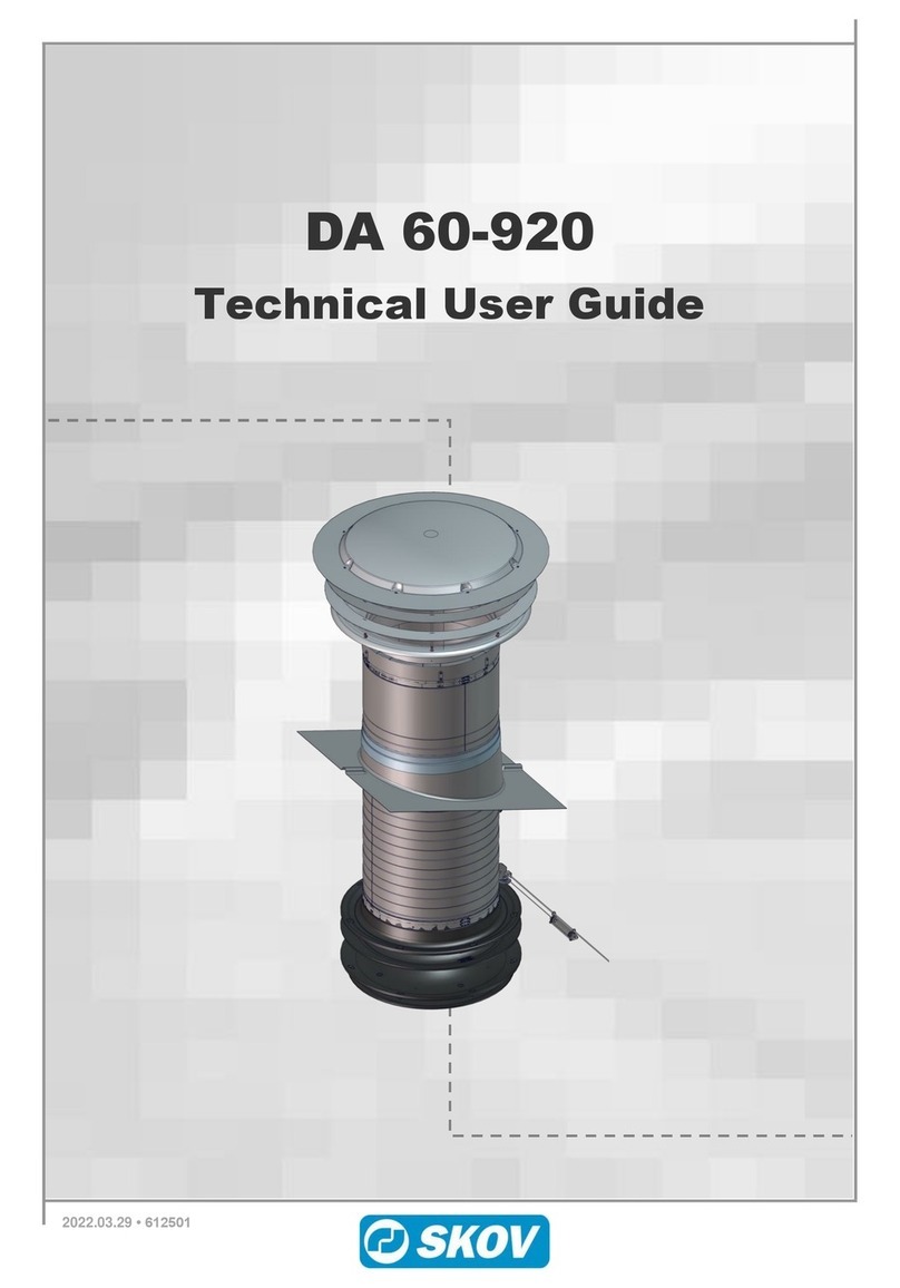
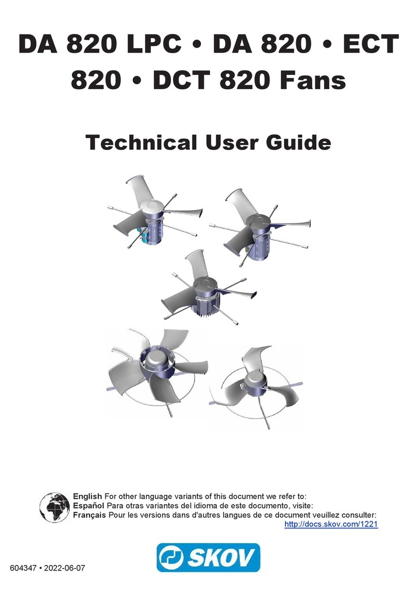
Skov DA 50-650 Manual

DA 50-650
Technical User Guide

2 Technical User´s Guide
DA 50-650
CONTENTS
1PRODUCT DESCRIPTION 4
2MOUNTING GUIDE 5
2.1 Introduction to the Mounting............................................................................ 5
2.1.1 The Appendixes are divided as follows:.......................................................................... 5
2.2 Placement in the House.................................................................................... 5
2.2.1 Examples of Placement in the House .............................................................................. 6
2.3 General Mounting.............................................................................................. 7
2.3.1 General Drawings ............................................................................................................. 7
2.3.2 Mounting of Roof Sheet.................................................................................................... 9
2.3.3 Assembling of Ducts.......................................................................................................... 9
2.3.4 Roof Flashing with Neoprene Cloth .............................................................................. 10
2.3.5 Assembling of Duct and Funnel Tube........................................................................... 11
2.3.6 Mounting of Roof Duct on Duct .................................................................................... 11
2.3.7 Mounting of Bell Mouth on Roof Duct ......................................................................... 12
2.3.8 Mounting of Net on Bell Mouth..................................................................................... 12
2.3.9 Mounting of Rain Screen on Net ................................................................................... 12
2.3.10 Mounting of Roof Cap on Net........................................................................................ 13
2.3.11 Mounting of Adjustment Fitting with Spring on the Bottom Plate............................ 13
2.3.12 Mounting of Intermediate Plate (optional equipment) and Bottom Plate ................. 14
2.3.13 Mounting of Recirculation Fan (optional equipment)................................................. 14
2.3.14 Measuring and Mounting of Pull Rod/Suspension ...................................................... 16
2.3.15 Fastening of Air Supply Unit to Pull Rod..................................................................... 17
2.4 Adjustment of DA 50-650 Air Supply Unit ......................................................18
3INSTALLATION GUIDE 20
3.1 Cable Chart for Recirculation Fan...................................................................20
3.2 Wiring Diagram for Recirculation Fan ............................................................21
3.3 Diagram for Rotating Direction of the Recirculation Fan ..............................22
4USER’S GUIDE 23
4.1 Cleaning............................................................................................................23
4.1.1 Dismantle Bottom Plate and Intermediate Plate for Cleaning ................................... 23
5MAINTENANCE INSTRUCTIONS 23
5.1 Instructions for taking down the Unit and Recycling ....................................23
6TROUBLE SHOOTING INSTRUCTIONS 24
7TECHNICAL DATA 25
7.1 Dimensioned Sketch DA 50-650 (in mm) ........................................................25
7.2 Tensile Force....................................................................................................26
7.3 Air Output .........................................................................................................26

Technical User´s Guide 3
DA 50-650
7.4 Technical Data Recirculation Fan ...................................................................26
8APPENDIX 1 27
8.1 Mounting Guide, Garret ...................................................................................27
9APPENDIX 2 28
9.1 Mounting Guide, free hanging Roof................................................................28
10 APPENDIX 3 30
10.1 Mounting Guide, free hanging Ridge..............................................................30
11 APPENDIX 4 32
11.1 Mounting Guide, Roof through Garret ............................................................32
12 APPENDIX 5 35
12.1 Mounting Guide, Ridge through Garret ..........................................................35
13 APPENDIX 6 37
13.1 Mounting Guide, Monoblock House ...............................................................37
14 APPENDIX 7 38
14.1 Mounting Guide, flat Roof................................................................................38

4 Technical User´s Guide
DA 50-650
1Product Description
The DA 50 Air Supply Unit is an air inlet, which combines high output with low air velocity in the
area occupied by the birds.
DA 50-650 performs up to 12,250 m3/h at 40 Pa negative pressure.
The high output is obtained without the use of a fan.
DA 50 has a parallel motion system, which ensures that the air supply unit opens uniformly all the
way around. This ensures a uniform air distribution in the entire house.
The 100 % stepless control ensures that the system can be adjusted to the required air jet range during
the concerned period of the year. Thus, it is possible always to make a combination of negative
pressure and opening, which provides the required relation between output and air velocity.
DA 50 is cast in double shell fibreglass for better insulation.
DA 50-650
A
DA 50-650 Roof cap
B
DA 50-650 Net
C
DA 50-650 Rain screen
D
DA 50-650 Bell mouth
E
DA 600 Roof duct
F
DA 600 Roof sheet
G
DA 600 Duct
H
DA 50-650 Funnel tube complete
I
DA 50-650 Intermediate plate
J
DA 50-650 Bottom plate
K
DA 50-650 Recirculation fan

Technical User´s Guide 5
DA 50-650
2Mounting Guide
2.1 Introduction to the Mounting
Check that all ordered parts are present and intact according to the delivery note before you start your
work.
This chapter concerns the general mounting of the DA 50-650 unit, regardless of the
type of building in which it is to be mounted.
As an appendix at the end of the document you find supplementary mounting guides,
which define the specific mounting conditions depending on the type of building
concerned.
2.1.1 The Appendixes are divided as follows:
▪Appendix 1, Mounting Guide, Garret
▪Appendix 2, Mounting Guide, free hanging Roof
▪Appendix 3, Mounting Guide, free hanging Ridge
▪Appendix 4, Mounting Guide, Roof through Garret
▪Appendix 5, Mounting Guide, Ridge through Garret
▪Appendix 6, Mounting Guide, Monoblock House
▪Appendix 7, Mounting Guide, flat Roof
2.2 Placement in the House
Place the DA 50-650DA 50-650 units in the house according to the enclosed drawing; however, the
placement depends on purlins, rafters etc. Contact SKOV A/S if there are considerable deviations.
Place the DA 50-650DA 50-650 units evenly distributed with the same spacing in the whole house.
The two units at each end of the house may be placed proportionally farther from the gable to reduce
down draught along the gable.
Check that all DA 50-650DA 50-650 units can be placed freely in relation to other equipment, which
may be mounted later, such as feed lift, water etc., however, as agreed with the building owner.
NB: Note the diameter of the plates for the DA 50-650DA 50-650 units when lifting them past the
feed lift, water etc.
The pull rod must be placed left of the DA 50-650DA 50-650 when you look towards the
winch motor. This also means that you must make sure that the large wire lock of the
DA 50-650 funnel tube is to the left.
IMPORTANT: If an insulated duct is to be mounted, see instruction 603819, which is enclosed with
the insulated duct.
IMPORTANT: If a recirculation fan is mounted, the distance from floor to fan must comply with the
current requirements and standards. According to DS/EN 294, the distance must be minimum 270 cm.

6 Technical User´s Guide
DA 50-650
2.2.1 Examples of Placement in the House
Figure 1
Example of a 50 m long house with one winch
motor.
Figure 2
Example of a 100 m long house with two winch
motors.

Technical User´s Guide 7
DA 50-650
2.3 General Mounting
2.3.1 General Drawings
Figure 3

8 Technical User´s Guide
DA 50-650
Figure 4
1. When the roof sheet is mounted and the roof duct, duct and roof cap (complete) are
assembled, these parts are to be put through the hole in the roof sheet.
Tip: Wait to fasten the roof duct to the roof sheet in view of the further mounting.
2. When the funnel tube and the duct are assembled, these parts are to be put through the hole in
the ceiling. Remember that roles on the funnel tube must be turned lengthwise of the
building. See section 1.2.1. Fasten the duct to the wooden frame.
3. Adapt the height of the last duct.
Mount the last duct on the other ducts.
Finally fasten the roof duct to the roof sheet.

Technical User´s Guide 9
DA 50-650
2.3.2 Mounting of Roof Sheet
Figure 5
▪Make the hole in the roof according to the instructions at the end of the document under
Appendix.
▪Mount the roof sheet firmly on the roof. If there are corrugated sheets, mount a screw in the
top of each wave.
▪Check if the top level is horizontal. Use a bubble level.
If the deviation is more than 0.5 cm, you must realign and drill new holes.
You can realign maximum 3.1 cm.
2.3.3 Assembling of Ducts
Figure 6
Assembling:
▪Mount every duct section by means of a light pressure, letting the labyrinth/bayonet lock
engage. Let go of the duct, it is now assembled.
▪When several ducts are mounted on top of each other, aim to offset the longitudinal
assembling 90°, so that the ducts maintain their round shape.
Adaptation of Length/Direction:
▪Mark out where to cut the duct, and cut off the redundant part.
▪Saw 40 mm off the longitudinal labyrinth lock from the top.
▪Mount the shortened part on the bell mouth or another duct by means of eight 6×16 mm
rustproof bolts with locknuts or twenty rustproof self-cutting screws of 4.2×12 mm.

10 Technical User´s Guide
DA 50-650
2.3.4 Roof Flashing with Neoprene Cloth
Cut out an adequate hole in the roofing sheet
With a 20oroof pitch. X= 780 mm. Y= 840 mm
The hole in the neoprene cloth must be approx.
15cm smaller than the diameter of the exhaust
unit. Note that at a roof pitch of 20o, the largest
diameter of the ellipse is 6 cm larger.
Apply a stripe of glue on the roofing sheet.
Apply a stripe of glue on the periphery of the
roofing sheet approx. 15cm above roof.
Pull the cloth into place over the duct and spread
it properly on the roof.
Place the top roofing sheets over the cloth.
Mount various screws for fixation of cloth and
roofing sheets.
Y
X
200

Technical User´s Guide 11
DA 50-650
2.3.5 Assembling of Duct and Funnel Tube
Figure 7
▪Place the duct on the inside on the recess plane of the funnel tube.
▪Drill eight Ø6.5 mm holes as marked out in the funnel tube.
▪Assemble the funnel tube and the duct by means of eight M6×50 bolts, eight M6 nuts and
sixteen washers.
2.3.6 Mounting of Roof Duct on Duct
Figure 8
▪Place the roof duct in the recess plane of the duct end.
▪Assemble the roof duct and the duct by means of eight assembling pieces, screws and
washers.

12 Technical User´s Guide
DA 50-650
2.3.7 Mounting of Bell Mouth on Roof Duct
Figure 9
▪Place the bell mouth in the recess plane of the roof duct.
▪Drill eight Ø6.5 holes as marked out in the roof duct.
▪Assemble the bell mouth and the roof duct by means of eight M6×25 bolts, eight M6 nuts and
sixteen washers.
2.3.8 Mounting of Net on Bell Mouth
Figure 10
▪Drill eight Ø6.5 mm holes as marked out in the bell mouth.
▪Assemble the bell mouth and the net by means of eight holders for wire mesh, eight 6×25 mm
screws and eight washers.
▪NB: The groove in the holder for wire mesh must engage with the wire at the bottom of the
net.
2.3.9 Mounting of Rain Screen on Net
Figure 11
▪Drill eight Ø5.5 mm holes in each rain screen as marked out.
▪Mount the rain screen on the net by means of strips.

Technical User´s Guide 13
DA 50-650
2.3.10 Mounting of Roof Cap on Net
Figure 12
▪Drill eight Ø6.5 mm holes as marked out in the roof cap.
▪Assemble the roof cap and the net by means of eight holders for wire mesh, eight 6×25 mm
screws and eight washers.
▪NB: The groove in the holder for wire mesh must engage with the wire at the top of the net.
2.3.11 Mounting of Adjustment Fitting with Spring on the Bottom Plate
Figure 13
▪Predrill Ø3.5 mm holes at the centre marks in the bottom plate.
▪Mount the four adjustment fittings with springs on the bottom plate according to the sketch.

14 Technical User´s Guide
DA 50-650
2.3.12 Mounting of Intermediate Plate (optional equipment) and Bottom Plate
Figure 14
▪Mount the intermediate plate (optional equipment) with string and bushes. Place the string up
around the axle on the inside of the wheel.
▪If required, mount the four enclosed sealing plugs.
▪Mount the bottom plate with wires and bushes.
2.3.13 Mounting of Recirculation Fan (optional equipment)
2.3.13.1 Mounting of Recirculation Fan on the Plate for Recirculation Fan
Figure 15
▪Predrill Ø3.5 mm holes at the centre marks.
▪Fasten the recirculation fan on the plate by means of four mounting fittings and four 6×30 mm
screws.
▪NB: The mounting fittings are in the box together with the fan.

Technical User´s Guide 15
DA 50-650
2.3.13.2 Mounting of Contact Box on the Plate for Recirculation Fan
Figure 16
▪Fasten the contact box on the plate by means of two 5×20 mm screws.
▪NB: It is important to observe the 110 mm measurement! Make sure not to drill/screw through
the plate, as this would allow water to leak into the cavity of the plate.
▪NB: The power to the recirculation fan should be supplied by a watertight CE plug in view of
dismantling during cleaning.
2.3.13.3 Suspension of complete Recirculation Fan
Figure 17
▪Mount the suspension for the recirculation fan in the four holes in the bottom plate.
▪Mount the plastic split pin from below and up through the hole.
▪Lift up the recirculation fan and mount it in the suspension.

16 Technical User´s Guide
DA 50-650
2.3.14 Measuring and Mounting of Pull Rod/Suspension
Figure 18
Figure 19
▪Measure the pull rod.
▪Assemble the pull rods by means of a splicing sleeve, and mount an eye joiner at the end
nearest to the winch motor. Mount a DA 50 mounting set for decentralized winch motor in the
eye joiner.
▪The required number of pull rod suspensions are drawn onto the pull rod. One pull rod
suspension is required for each 3 metres of free-hanging pull rod so the pull rod is in a level
position between the DA 50-650 units.
▪NB: Splicing sleeves are not to move past the suspension during operation. You may move the
suspension accordingly.
▪Mount pull rods in the groove of the wheel holder.
▪The ceiling hook of the pull rod suspension is mounted in the ceiling and the nylon cord is
adjusted by means of the sliding sleeve so the pull rod is level.
▪NB: When the winch motor is completely closed, the pull rod must extend 200 mm from the
last wheel holder opposite the winch motor.
▪It is not necessary to use a coil spring. There is a back-pull of 15-25 kg from each air supply
unit.

Technical User´s Guide 17
DA 50-650
2.3.15 Fastening of Air Supply Unit to Pull Rod
Figure 20
Figure 21
▪The pull rod must be placed to the left of the DA 50-650DA 50-650. See section 2.2.1.
This also means that you must make sure that the large wire lock of the DA 50-650 funnel
tube is to the left.
▪Run the winch motor to completely closed position.
▪Lift/pull the air supply units up to completely closed position. Tighten the wire with the large
wire lock and clamping sleeves for pull rod and mount it on the pull rod in the direction
towards the winch motor.
▪In view of the later adjustment, only the first unit in each row, closest to the winch motor,
should be connected to the pull rod at first.

18 Technical User´s Guide
DA 50-650
2.4 Adjustment of DA 50-650 Air Supply Unit
The distance from the bottom of the drip nose (point a) of the air supply unit to the edge of the
intermediate plate (point c) must be c 150 mm. (Is delivered prefabricated in correct length).
The distance from the bottom of the drip nose (point a) of the air supply unit to the edge of the bottom
plate (point b) must be c 420 mm +/- 50 mm. The distance must be the same at all four suspension
points.
If the bottom plate does not have the same distance in one or more suspension points, you must loosen
the counternut and adjust the wing nut until there is the same distance at all four suspension points.
Remember to tighten the counter nut again.
SKOV A/S recommend using the following adjustment procedure:
The winch motor must open at slack and have a shift of c 375 mm.
Run the winch motor up and down three or four times so that it ends in a completely closed position.
Now check the following distances of the first air supply unit in each row:
The bottom plate must close completely. Adjust the four corners so that the springs have a pretension/
press of c 0.5 cm on the first unit in each row.
Then run the winch motor to completely open position. The distance between a and b must be c 420
mm +/- 50 mm. If this is not the case, the winch motor should be rewound. If this is OK, run the winch
motor to completely closed position again. Possibly check the pretension of the springs of c 0.5 cm
again.
Hereafter open the system so that there is c 1 cm opening between the air supply unit and the
intermediate plate. Find the shortest distance at the four corners; this must be c 1 cm. Adjust the
remaining three corners to c one cm also, possibly use a precision feeler gauge.
If the distance is not the same between the rows, the shortest distance must be used as basis.
Then connect the remaining units to the pull rod.
Now adjust the remaining units to the same distance as achieved for the first units. Remember that all
four corners must have the same distance.
After finishing the adjustment, run the winch motor to completely open again. The distance between
point a and b must still be within c 420 mm +/- 50 mm.
NB: It is important that all units open evenly at minimum opening.
(It is less important if the units have the same opening at full opening).

Technical User´s Guide 19
DA 50-650
Figure 22

20 Technical User´s Guide
DA 50-650
3Installation Guide
3.1 Cable Chart for Recirculation Fan
Figure 23
▪Level detector and switch may possibly be mounted in the controller/computer on a DIN bar.
▪A Switch must be used if there are more than three fans. Is not supplied by SKOV A/S.
▪NB: Power to the recirculation fan should be supplied by means of a watertight CE plug in
view of dismantling during cleaning.
Table of contents
Other Skov Fan manuals

Skov
Skov BF 55 Manual

Skov
Skov DA 1700 Manual

Skov
Skov DA 1700 LPC -3 Manual

Skov
Skov DA 820 LPC Manual

Skov
Skov BF 50 Manual

Skov
Skov DA 60-920 Manual

Skov
Skov DA 1200 Installation instructions manual

Skov
Skov ECT 632-6 Manual

Skov
Skov DA 1200 Wall Inlet Installation instructions manual

Skov
Skov DA 1700 Manual
Popular Fan manuals by other brands

Hunter
Hunter 59515 Five Minute Fan Owner's guide and installation manual

EWT
EWT Oscillor user manual

Mistral
Mistral MSF1835 Owner's Manual & Installation Instructions

Monte Carlo Fan Company
Monte Carlo Fan Company 5PAR52 Series owner's manual

Lennox
Lennox Enlight LGT Series manual

Delta Electronics
Delta Electronics GFB0405HF Dimensions and installation information