Remedy
1. Replacefuseorresetbreaker.
2. Repairor replace wire fastenersat
dishwasherjunctionbox.
3.Replacetimer.
4. Replacemotor/impellerassembly.
5. Replacedoorswitch.
6. Replacelatchassembly.
7. Replaceselectorswitch.
1. Replacemotor.
2. Rotatemotorfanorimpeller.
1. Checkvoltage.
2. Rotate motor fan or impeller, or
replace.
3. Clearblockageorreplace.
4. Replacemotor/impellerassembly.
5. Cleanandclearblockage.
1. Replaceheaterelement.
2. Replacetimer.
3. Repairorreplace.
4. Replacethermostat.
1. Replacedispenser.
2. Replacetimer.
3. Repairorreplace.
4. Replacedispenser.
5. Replaceactuator.
1. Clearrestrictions.
2. Replacetimer.
3. Replacepump.
4. Makesurehoseis attached inproper
positiononsideoftub.
5. Checkforblockage,clear.
6. Replacewindings.
1. Turnwatersupplyon.
2. Replacewaterinletfillvalve.
3. Disassembleandcleanscreen.
4. Repairorreplace.
5. Replacetimer.
6. Repairorreplace.
7. Cleanfloat.
1. Replacetimer.
2. Repairorreplacetimer.
3. Repairoradjust.
4. Replace or adjust position of
thermostat.
1. Repairtoproperheight.
2. Installairgapatcountertop.
3. Reattachdrainhose.
1. Instructcustomer/user.
2. Instructcustomer/user.
3. Instruct customer/user on proper
loadingofdishes.
4. Incomingwatertemperatureof120°F
is required to properly dissolve
dishwashingdetergents.
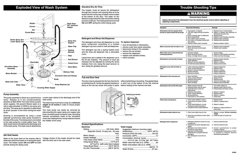
TroubleShootingTipsExplodedViewofWashSystem
Tub and Door Seal
Thedoorsealispressedintothetubchannel for
aninterferencefit.Centerthegasket(markedon
back)at the tub top centerand press in place
ProductSpecifications
Electrical
Rating .......................... 120Volts,60Hz
SeparateCircuit..15ampmin.-20ampmax.
Motor(Amps) ................................. 1.1
HeaterWattage .............................. 900
TotalAmps(loadrated) ................... 10.0
TempBoost(somemodels) .... 122°F(50°C)
HeatedWash/HeatedRinse
Hi-LimitThermostat ............. 200°F(93°C)
WaterSupply
Suggestedminimumincomingwater
temperature ...................... 120°F(49°C)
Pressure(PSI)min./max. ............... 20/120
Connection(NPT) ............................ 3/8"
Consumption(NormalCycle) .................
....... 6.0U.S.gal.,5.0 Imp.gal.,22.7 liters
Watervalveflowrate(U.S.GPM) ....... .83
Waterrecirculationrate(U.S.GPM) ..........
........................................ approx.12
Waterfilltime ............................ 87sec.
Detergent and Rinse Aid Dispenser
Thedetergentand rinseaiddispenser isaone
piece component consisting of a molded
detergentcupandabuilt-inrinseaiddispenser.
Thedetergent cuphas aspring loaded cover
andthe rinse aiddispenser has aremovable
cover.
Liquidrinseaid isaddedto thedispenserup to
thefill line indicator. The amount of rinseaid
releasedcanbe adjusted byturningthe arrow
indicatorfromone, beingthe leastamount,to
four,beingthegreatestamount.
To replace dispenser:
shutoffelectricitytodishwasher,
removeouterdoorpanelassembly,
disconnectwiringtotheactuator,
removethesixscrews,
removethedispenser,
replaceandreinstallscrews,
rewireactuator.
To replace actuator:
shutoffelectricitytodishwasher,
disconnectwiringtotheactuator,
placeaflathead screwdriverunderthe
actuatorbodyandbetweenthedispenser
housingandterminalside,twistandliftup
ontheactuatorbeingcareful nottodamage
theretainersnap-fits,
replacewithnewactuatorbypressinginto
place,
rewireactuator.
StandardDry Air Flow
Whenthecontroladvancestothedryportionof
the cycle, a linear actuator retracts a valve,
whichopens a ventpath throughtheconsole
intothekitchen.Thisventingmethodeliminates
dischargingheated moisture intothe motor
compartment.Theheated,moistairleavingthe
dishwasherthroughthe consoleventcauses
drierairtobedrawnintotheunitbywayofintake
ventslocated at the bottom of the door.The
wateronthe dishesisevaporated intodrierair
andtheventingprocesscontinues.Theheating
elementisturnedON andOFF duringthe entire
dryingcycle.
PowerDry AirFlow
ThePowerDryconfigurationisthesameasthe
Standardexceptithasacrossflowblowerlocated
intheairdischargepath.Theblowerassiststhe
heatingelementinproducingpowertodrivethe
moistairoutofthedishwasher.
Check the Following
1. Fuse(blownortripped).
2. 120VACsupplywiringconnection
faulty.
3.Timer(contactsopenordefective)
4. Motor(inoperative,check
resistances).
5. Doorswitch(open contacts).
6. Doorlatchnot makingcontactwith
doorswitch.
7. Selectorswitch(opencontacts).
1. Motor(badbearingsor locked
rotor).
2. Motorstuckdue toprolonged
non-use.
1. Impropervoltage.
2. Sealfacesbinding.
3. Motorshaftbinding.
4. Motorwindingsshorted.
5. Glassorforeignitems in pump.
1. Heaterelement(open).
2. Timerdefective.
3. Wiringorterminaldefective.
4. Hi-limitthermostatdefective.
1. Latchmechanismdefective.
2. Timercontactdefective.
3. Wiringorterminaldefective.
4. Brokenspring(s).
5. Defectiveactuator.
1. Drainrestricted.
2. Timercontactdefective.
3. Defectivedrainpump.
4. Airlockindrainhose.
5. Blockedimpeller.
6. Openwindings.
1. Watersupplyturned off.
2. Defectivewaterinletfillvalve.
3. Checkfillvalvescreenfor
obstructions.
4. Defectivefloatswitch.
5. Timercontactdefective.
6. Wiringdefective.
7. FloatstuckinUP position.
1. Timermotor(stalledoropen.)
2. Checktimerforpower to timer
motor.
3. Timershaftbindingto orknob
interferencewithescutcheon.
4. TempBoostthermostatdefective.
1. Drainhose(high)looptoo low.
2. Drainlineconnectedtoafloordrain
notvented.
3. Drainhosenotconnectedtoside of
tub.
1. Detergentallowedtostand toolong
indispenser.
2. Dispenserwetwhendetergentwas
added.
3. Detergentcoverheldclosedor
blockedbylargedishes.
4. Improperincomingwater
temperaturetoproperly dissolve
detergent.
5. See"Detergentcoverwillnot
open."
Always disconnect the dishwasher from the electrical power source before adjusting or
replacingcomponents.
Personal Injury Hazard
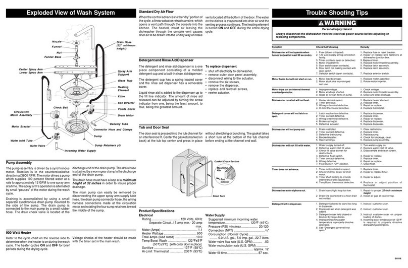
Nozzle
Funnel
Nut
FunnelBase
CenterSpray Arm
LowerSprayArm
Delivery Tube
ConnectorHose
Sump
WaterValve
WaterInletTube
Check Ball
CirculationMotor
Assembly
MotorBracket
900WattHeater
Referto the cyclechart on the reverse sideto
determinewhentheheaterisonduringthewash
cycle.The heatercycles ON and OFF forbrief
periodsduringthedryingcycle.
Voltagechecks ofthe heatershould be made
withthetimersetinthemainwash.
airlock. The drain loop on the side of thetub
mustbekept in placeafterservicing.
The main pump can easily be removed by
disconnectingtheuppersprayarmsupplytube,
thedrainpumpconnectorhose,andthewiring
harnessconnections madeat thecirculation
motorandthewaterheatthermostatslocatedon
thebottomofthepump.
Oncethepumpassemblyis removed fromthe
dishwasher,themotor/impellerassembly can
beremoved fromthe sumpby taking outthe
three (3) T-20 Torx head screws from the
aluminummotorbracketandthenthethree(3)
T-20Torxhead screwsfromthe volutecover.
Usinga large flat head screwdriver inserted
betweenthe impellerscrew andthe sumps
volute,themotor/impellerassemblycanbegently
priedoutofthesump.Use the screwdriverasa
lever.
PumpAssembly
The pump assembly is driven by a 1/12 HP,
shaded pole motor. Rotation is in the
counterclockwisedirectionat3100to3200RPM.
Themotordrives apumpwhich supplies100
percentfilteredwaterataratetoapproximately
12GPMto onesprayarm ata time. Thespray
armsoperationisalternatedbysmallpauses
ofthemotorduringthewashcycle.
Draining is accomplished by using a small
separatesynchronousdrainpumpmountedto
thesideofthesump.Thedrainpumpisconnected
tothemain pumpbya smallrubberhose. The
draincheck valveis locatedat the entrance to
thedrainpump.Thedrainhoseisattachedbya
wormgearclampto thedischargeofthe drain
pump.Thedrainisthenroutedupthesideofthe
dishwasherandattachedtothesideofthetub.
Thisdrainloopinsuresthatanairpocketcannot
formnearthedrainpumpandcausethepumpto
Symptom
Dishwasherwillnotoperatewhen
turned on (wait at least 90 seconds).
Motor hums but will not start or run.
Motor trips out on internal thermal
overload protector.
Dishwasher runs but will not heat.
Detergent cover will not latch or
open.
Dishwasherwillnotpumpout.
Dishwasher will not fill with water.
Timer does not advance.
Dishwasherwatersiphonsout.
Detergent left in dispenser.
withoutstretchingorbunching.Thegaskettakes
ashort turn atthe bottom ofthe tub channel
beforeendingatthechannelend wall.
Tub
Interior
Mounting
Rib
Gasket Cross Section
ShortTurn
IncomingWaterSupply
DrainHose
SprayArm
Support
GlassTrap
Heating
Element
Filter
Soil Director
Volute Cover
DrainMotor
991221
