9
for connecting the supply wires to the unit.Use of rain
tight conduit is recommended.
• Seetheunitwiringlabelforproperhighandlowvoltage
wiring. Make all electrical connections in accordance
with all applicable codes and ordinances.
CAUTION:
Label all wires prior to disconnection when
servicing controls. Wiring errors can cause
improperanddangerousoperation.Verifyproper
operation after servicing.
• Units are shipped from the factory wired for 240 volt
transformeroperation.For208Voperation,removethe
lead from the transformer terminal marked 240V and
connect it to the terminal marked 208V.
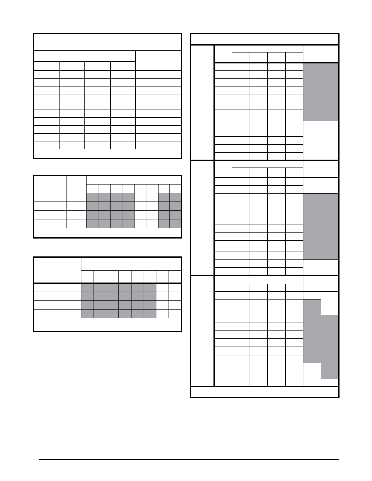
Table 4 (page 10) lists the basic airflow values versus the
airflow selector switch settings and the range of basic
air flow settings recommended for each nominal system
capacity.
NOTES:
• TheCFMvalueslisted in the tablesarenotdependent
on duct static pressure. The motor automatically
compensatesforchangesinductstaticpressure(within
the limits of the motor).
• Formaximumcapacityandenergyefficiency,selectan
airflow at or near the top of the range for that nominal
capacity.
• For maximum dehumidification, select an airflow near
the middle or bottom of the range for that nominal
capacity.Additional information on humidification and
dehumidification can be found on page 13.
• If coil icing is observed, the basic cooling/heat-pump
airflowselectedmaybetoo low.Checkthesetting and
make sure it is within the range shown inTable 4.Also
verify the system is properly charged. See charging
charts on pages 20 - 21. If icing continues to occur,
raise the selected airflow one or two steps.
Selecting the Minimum Electric Heat Airflow
The minimum electric heat airflow is selected by setting
switches 5 and 6. Selecting the minimum electric heat
airflow sets the minimum air flow that will be produced
whenever electric heater kits are used.When the electric
heater kits are energized along with a heat pump, the
airflow may be higher depending on the basic cooling/
heat-pump airflow setting.
SeeTable2(page10)forrecommendedminimumelectric
heat airflow settings. The minimum electric heat airflow
setting may be set higher, but must never be set lower
than the setting shown in the table.
Selecting the Delay Profile
Delayprofileselectioncontrolsthestart-upandshut-down
characteristicsofthepackagedheatpumpunit.Byvarying
thestart-upandshut-downcharacteristics,thesystemcan
be optimized for energy efficiency, humidity control, and
comfort.The delay profile is selected by setting switches
7 & 8 (See Table 3 page 10).Select Delay A or Delay B
for highest energy efficiency:
• Delay A has a two-step ON delay. The blower will
begin operation at 31% airflow for 30 seconds. The
second step operation is 75% airflow for 30 seconds.
After the two-step ON delay has been completed, the
blower operation will run at 100% until the thermostat
hasbeensatisfied.DelayAalsoprovidesa60second
OFF delay at 50% airflow.
• DelayB has a single step30secondONdelayat50%
airflow and also provides a 90 second OFF delay at
50% airflow. Select the delay profile which is most
suited to the application. See Table 3.
• TheDeHum delayprofilemaybe used whenhumidity
control is needed without the use of an optional
Grounding
WARNING:
The unit cabinet must have an uninterrupted or
unbroken electrical ground to minimize personal
injury if an electrical fault should occur. Do not
use gas piping as an electrical ground!
This unit must be electrically grounded in accordance
with local codes or, in the absence of local codes, with
the National Electrical Code (ANSI/NFPA 70) or the CSA
C22.1ElectricalCode.Use thegroundinglug provided in
the control box for grounding the unit.
Selecting Proper Airflow for Variable Speed Units
Th Q4SE packaged heat pump is equipped with a
microprocessor-controlled variable speed motor that is
pre-programmedtodeliveroptimumairflowinavariety of
conditions and system configurations.The unit responds
directly to the thermostat inputs, as well as the optional
humidistat(Ifinstalled).Duringnormaloperation,themotor
will gradually change speeds during start-up, shut down,
whenthermostatinputschange,and whentheductstatic
pressurechanges(ventsclosedoropened,filterclogging,
etc.). The heat pump unit is also configured by setting
the selector switches and removing jumper connectors
as directed below.
NOTE: This packaged heat pump has been designed to
give the installer maximum flexibility to optimize system
performance, efficiency, and comfort. With so many
different ways to set up the packaged heat pump, it is
important to read and follow all directions carefully.
Selecting the Basic Cooling/Heat Pump Airflow
Thebasiccooling/heat-pumpairflowisselectedbysetting
switches1-4onthethermostatinputboardlocatedonthe
blower. All airflows for other modes of operation (except
electric heat) are determined by this basic setting.