30" ELECTRIC RANGE INSTALLATION INSTRUCTIONS
(For 3 or 4 Wire, 60 Hz. Systems)
2
IMPORTANT SAFETY INSTRUCTIONS
Iftheinformationinthismanualisnotfollowed
exactly,afireorelectricalshockmayresultcausingproperty
damage, personal injury or death.
Important Notes to the Installer
• Read all instructions contained in these installation
instructions before installing range.
• Removeallpackingmaterialfromtheovencompartments
beforeconnectingthegas&electricalsupplytotherange.
• Observe all governing codes and ordinances.
• Be sure to leave these instructions with the consumer.
Important Note to the Consumer
Keep these instructions with your owner's guide for future
reference.
• Aswhenusing any appliancegeneratingheat,thereare
certain safety precautions you should follow. These are
listed in the Use & Care Manual, read it carefully.
• Besureyourrangeisinstalledandgroundedproperlyby
a qualified installer or service technician.
• Make sure the wall coverings around the range can
withstandthe heatgenerated bythe range.
• Toeliminatetheneedtoreachoverthesurfaceelements,
cabinet storage space above the elements should be
avoided.
BEFORESTARTING
Tools You Will Need
For leveling legs and Anti-Tip Bracket:
• Adjustable wrench or channel lock pliers
• 5/16" Nutdriver or Flat Head Screwdriver
• Electric Drill & 1/8" Diameter Drill Bit
(Masonry Drill Bit if installing in concrete)
For electrical supply connection:
• 1/4" & 3/8" Socket driver or Nutdriver
AdditionalMaterialsYou WillNeed:
• Power Supply Cord or
• Copper Electrical Wiring & Metal Conduit
(for hard wiring)
NORMALINSTALLATIONSTEPS
1. ANTI-TIPBRACKETINSTALLATIONINSTRUCTIONS
-IMPORTANTSAFETYWARNING
To reduce the risk of tipping of the range, the range must
be secured to the floor by properly installed Anti-Tip
Bracket and screws packed with the range. Failure to
install the anti-tip bracket will allow the range to tip over if
excessive weight is placed on an open door or if a child
climbs upon it. Serious injury might result from spilled hot
liquids or from the range itself.
If range is ever moved to a different location, the Anti-Tip
Bracketmust alsobe movedand installedwith therange.
Instructions are provided for installation in wood or cement
fastened to either the floor or wall. When installed to the
wall,make surethat screwscompletelypenetrate drywall
and are secured in wood or metal. When fastening to the
floor or wall, be sure that screws do not penetrate electrical
wiring or plumbing.
1a. Locate the Bracket
using the Template -
(Bracket may be located
on either the left or right
side of the range. Use the
informationbelowtolocate
the bracket if template is
notavailable).
Mark the floor or wall where left or right side of the range
will be located. If rear of range is against the wall or no
further than 1-1/4" from wall when installed, you may use
the wall or floor mount method. If molding is installed and
does not allow the bracket to fit flush against the wall,
remove molding or mount bracket to the floor. For wall
mount, locate the bracket by placing the back edge of the
templateagainst therearwall andthe sideedgeof template
on the mark made referencing the side of the range (See
Fig. 4). Place bracket on top of template and mark location
of the screw holes in wall. If rear of range is further than
1-1/4" from the wall when installed, attach bracket to the
floor. For floor mount, locate the bracket by placing back
edge of the template where the rear of the range will be
located. Mark the location of the screw holes, shown in
template.
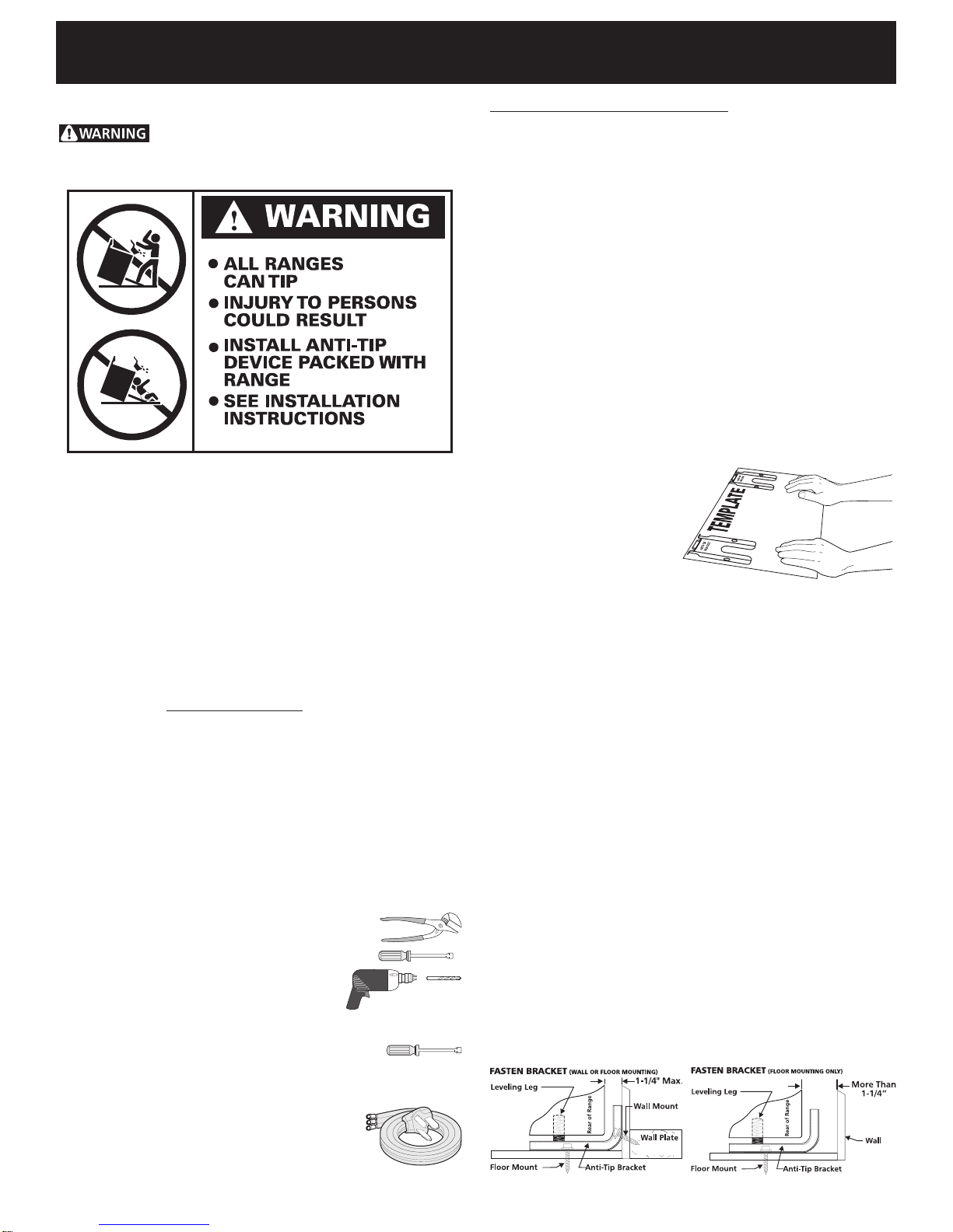
1b. Drill Pilot Holes & Fasten Bracket - Drill a 1/8" pilot
hole where screws are to be located. If bracket is to be
mountedto thewall, drillpilothole atan approximate20°
downward angle (See Fig. 5).
If bracket is to be mounted to masonry or ceramic floors,
drill a 5/32" pilot hole 1-3/4" deep. The screws provided
Fig. 4
Fig. 5 Fig. 6


