Page 7
3. INSTALLATION
Fridges & Freezers Boxes
SERIE MS STAINLESS STEEL
Series
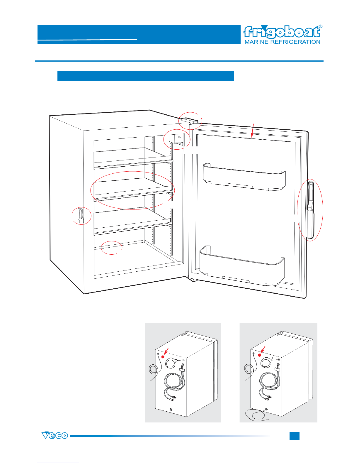
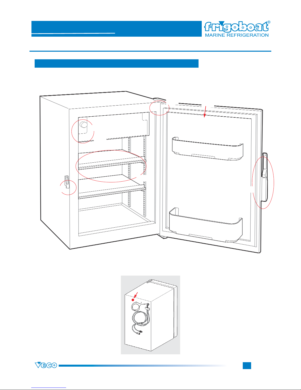
3.1 Doors/hinges
IF IT IS NECESSARY FOR INSTALLATION EXIGENCIES TO CHANGE THE OPENING, READ WITH
GREAT ATTENTION THE FOLLOWING INSTRUCTIONS.
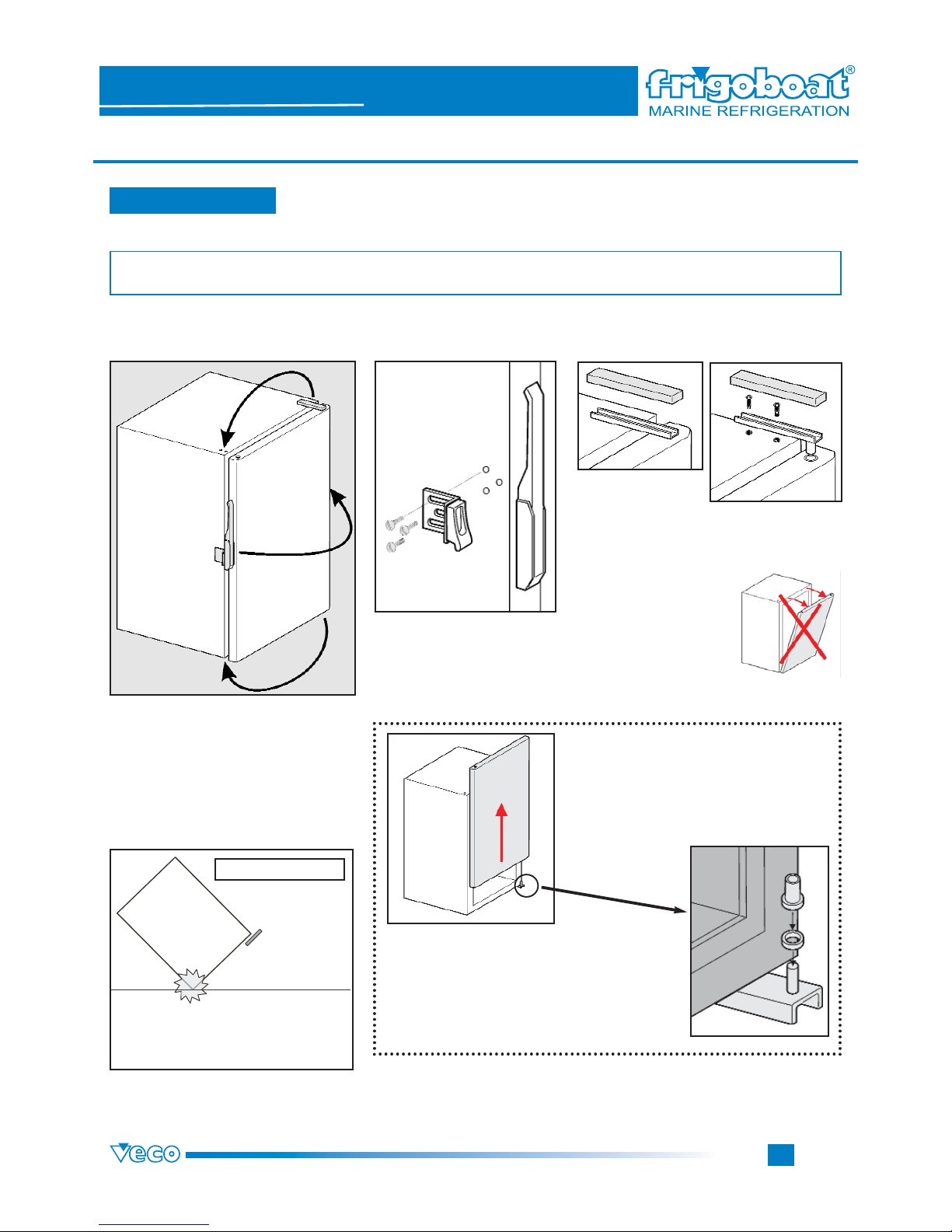
HINGE AND HANDLE REVERSAL
Release the hinge
plastic cover.
Unscrew the hinge screws on the cabinet
top. Removing the hinge, pay attention to the
door flection. Keep it clo-
sed until the hinge pin has
been unhooked. DON’T
FLEX BACK THE DOOR.
After having unscrewed the door, screw the hin-
ges on the opposite side (following the inverted
dismounting instructions). First of all, fasten the
inferior hinge, then hook the door and finally
fasten the superior hinge. Hook the handle to the
fridge/freezer,
Follow the instructions on page 7.
DURING THE DISMOUNTING, PAY
ATTENTION NOT TO LOSE THE RIN-
GLETS ON THE INFERIOR HINGE.
HOOK THE DOOR PUTTING THE RIN-
GLETS AS WE CAN SEE IN THE PICTU-
RE.
After having hooked the handle, adjust the door. Make sure that all
screws are tightened and then screw the plastic cover.
First of all, unscrew the handle
from the door and from its sup-
port. Then unscrew the corre-
sponding handle hook-up on
the box door side.
IMPORTANT: There are hin-
ges both at the top and at the
bottom.
ATTENTION
Unscrewing the hinges, pay attention
not to incline the fridge/freezer to
avoid ruining its corners.
12
4
3