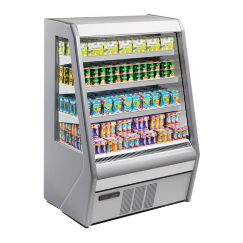
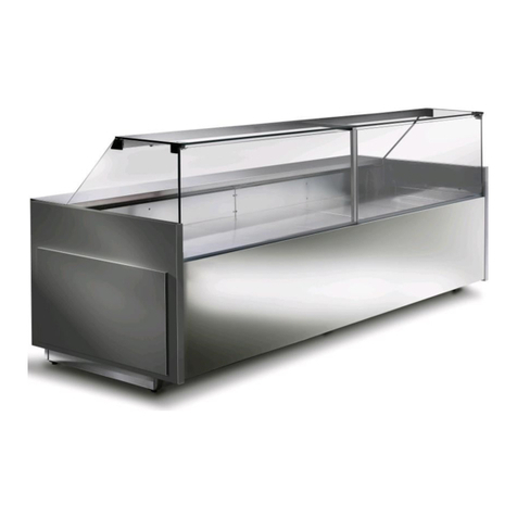
frost-trol WALEN Manual

TRANSLATION OF THE
ORIGINAL DOCUMENT Foradditionalcopiesvisit:
www.frost‐trol.com Versión: 1
D008586
INSTALLATION AND MAINTENANCE MANUAL
WALEN
SOLID LINES

INSTALLATIONANDMAINTENANCEMANUAL
TRANSLATION OF THE
ORIGINAL DOCUMENT Foradditionalcopiesvisit:
www.frost‐trol.com
WALEN SOLID LINES
D008586 Versión: 1 -2-
Index
EEC DECLARATION OF CONFORMITY...............................................................4
SAFETY ADVICE............................................................................................5
1.GENERAL INFORMATION ..................................................................8
1.1.DESCRIPTION OF REFRIGERATED DISPLAY CABINET............................9
1.2.GENERAL CHARACTERISTICS............................................................9
1.3.TECHNICAL INFORMATION AND ACCESS TO EPREL ............................ 10
1.4.SHOP CONDITIONS ....................................................................... 10
1.5.FIXATION OF THE RECOMMENDED TEMPERATURE IN EACH
COMPARTIMENT ......................................................................................... 11
1.6.OPERATING THE COOLING SYSTEM.................................................. 11
1.7.RECEIPT OF REFRIGERATED CABINET .............................................. 11
1.8.DAMAGE SUSTAINED IN TRANSIT.................................................... 12
1.9.TECHNICAL ASSISTANCE................................................................ 12
1.10.STORAGE..................................................................................... 12
2.INTALLATION OF REFRIGERATED DISPLAY CABINET........................... 13
2.1.CABINET LOCATION....................................................................... 13
2.2.UPACKING.................................................................................... 13
2.3.LEVELLING ................................................................................... 14
2.4.INSTALLATING THE DRAINAGE SISTEM* .......................................... 14
2.5.REFRIGERATING SYSTEM CONNECTION*.......................................... 15
2.6.INSTALLATION’S DRYING*.............................................................. 15
2.7.THERMOSTATIC VALVE CONTROL*................................................... 15
2.8.ELECTRICAL CONNECTION.............................................................. 16
2.9.CLEANING.................................................................................... 17
3.OPERATION.................................................................................. 18
3.1.INITIAL START-UP......................................................................... 18
3.2.PRODUCT LOADING AND PRESERVATION.......................................... 18
4.MAINTENANCE AND CLEANING........................................................ 20
4.1.GENERIC CLEANING ROUTINE......................................................... 20
4.2.INTERNAL CLEANING PROCEDURE................................................... 21
4.3.CONDENSER CLEANING PROCEDURE*.............................................. 21
4.4.SLIDING DOORS MAINTENANCE...................................................... 22
5.SPARE PARTS REQUEST ................................................................. 23
6.FAULTS AND REPAIRS.................................................................... 24
6.1.MALFUNCTIONS ............................................................................ 24
6.1.1.THE UNIT DOESN’T START UP OR IT STOPS:..................................... 24
INSTALLATIONANDMAINTENANCEMANUAL
TRANSLATION OF THE
ORIGINAL DOCUMENT Foradditionalcopiesvisit:
www.frost‐trol.com
WALEN SOLID LINES
D008586 Versión: 1 -3-
6.1.2.THE UNIT DOES NOT GET COLD ENOUGH:........................................ 24
6.2.FINAL SHUTDOWN......................................................................... 26
6.3.DISMANTLING THE CABINET........................................................... 26
6.4.DECLARTION OF ROHS CONFORMITY ............................................... 27
7.GUARANTEE ................................................................................. 27


INSTALLATIONANDMAINTENANCEMANUAL
TRANSLATION OF THE
ORIGINAL DOCUMENT
Foradditionalcopiesvisit:
www.frost‐trol.com
WALEN SOLID LINES
D008586 Versión: 1 -5-
SAFETY ADVICE
This cabinet may contain flammable refrigerant R290.
The refrigerated display cabinet must not be installed in places where
explosive gases are present. Do not expose the equipment to
atmospheric agents.
Packaging materials (plastic bags, nails, screws, polystyrene, etc.)
should not be left within reach of children as they pose potential
sources of danger.
Poor levelling could result in problems with the drainage of water
resulting from defrosting, which could cause the unit to break down.
It’s mandatory to leave 8cm between the cabinet rear wall and the
supermarket wall to ensure the airflow.
Keep clear of obstructions all ventilation openings of the cabinet
enclosure.
Don’t use metallic or cutting objects to accelerate the defrost process.
It may scratch or damage inner surfaces.
Gloves should be worn to protect hands when cleaning inside the
evaporator and the condenser. This will protect hands against possible
cuts or scratches from the unit’s internal elements.
Make sure that the drainage holes are not obstructed by any
remaining merchandise, as this could impede the drainage of excess
water resulting from defrosting.
Do not use any electrical appliances inside the storage compartments
for the food frozen by the equipment, unless recommended by the
manufacturer.
Do no damage the refrigerating circuit.

INSTALLATIONANDMAINTENANCEMANUAL
TRANSLATION OF THE
ORIGINAL DOCUMENT
Foradditionalcopiesvisit:
www.frost‐trol.com
WALEN SOLID LINES
D008586 Versión: 1 -6-
Do not expose the equipment to atmospheric agents.
Do not store explosive substances such as aerosol cans with a
flammable propellant in the refrigerated cabinet.
Keeping pharmaceuticals, glass bottles or flasks in the cabinet is
strictly forbidden.
Only qualified personnel can remove panels or guards, and specially
the electric board cover, when this requires the use of tools.
Before obtaining access to terminals, all supply circuits must be
disconnected.
Unplug the cabinet before performing any form on internal servicing of
the unit.
The power cords must be properly spread out, safe from shocks and
far from liquids, water and heat sources, and in perfect condition. The
use of adaptor plugs is forbidden.
If the power cord is damaged, it must be replaced by the
manufacturer in order to avoid a hazard.
Earthing is mandatory according to current legislation, as is providing
protection against power surges, short circuits and indirect contacts.
Ensure that the power supply voltage meets the details on the rating
plate of the cabinet. The cabinet must be properly connected to the
earthing system.
Do not use direct or indirect water jets on the cabinet. Do not touch
the equipment with damp or wet hands or feet; do not use it while
barefoot.
Parts that form the refrigeration circuit must not be cut or separated
until the refrigerant has been removed for recovery at a specialized
centre.

INSTALLATIONANDMAINTENANCEMANUAL
TRANSLATION OF THE
ORIGINAL DOCUMENT
Foradditionalcopiesvisit:
www.frost‐trol.com
WALEN SOLID LINES
D008586 Versión: 1 -7-
The components of the refrigerating circuit must not be cut or
separated.
It is completely forbidden to perforate the cabinet. If this occur, it
could create irreparable damages.
If you wish to stick adhesive signs onto the cabinet, only use thin foil.
Do not lay thick insulating layers on the external walls of the
equipment as this could compromise cabinet performance.
In order to reduce flammability-related risks, this cabinet may only be
installed by suitably qualified personnel.
Product that you load into the cabinet must always be cooled to at
least the cabinet's conservation temperature. The cabinet is not able
to reduce the temperature of products, only conserve them.
Gloves should be worn during product loading operations.
Any other use not explicitly mentioned in this handbook must be
considered as hazardous. The manufacturer disclaims all liability for
damage resulting from improper, incorrect or unreasonable use.

INSTALLATIONANDMAINTENANCEMANUAL
TRANSLATION OF THE
ORIGINAL DOCUMENT Foradditionalcopiesvisit:
www.frost‐trol.com
WALEN SOLID LINES
D008586 Versión: 1 -8-
1. GENERAL INFORMATION
Welcome to the new series of refrigerated display cabinet modules from Frost-Trol
for the sale of perishable food products. We are delighted by your decision to
choose us.
This assembly and maintenance manual has been especially designed with a view
to assist maintenance staff by facilitating the installation of these cabinets, thus
making their task more pleasant, as well as to gain optimal productivity from these
units and also so that the Marketing Director is able to gain the maximum
commercial return possible.
Read this manual carefully and store it with the refrigeration unit. Pay
particular attention to the sections that emphasize your safety. Follow these
instructions to ensure that the unit will run smoothly and its life span may be long
and productive.
We are open to any suggestions that you might have concerning the design of this
manual. Please write to the following address or call us on the telephone number
given below:
The A-weighted emission sound pressure level is below 70dB(A).
Frost-trol, S.A.
Technical Department
Avda. del Castell Vell, 176
12004 Castellón (Spain).
Tel.: 0034 964 34 27 40
Fax: 0034 964 21 51 48
www.frost-trol.com

INSTALLATIONANDMAINTENANCEMANUAL
TRANSLATION OF THE
ORIGINAL DOCUMENT Foradditionalcopiesvisit:
www.frost‐trol.com
WALEN SOLID LINES
D008586 Versión: 1 -9-
1.1. DESCRIPTION OF REFRIGERATED DISPLAY
CABINET
Walen is a refrigerated cabinet characterized by its large exhibition area, an ideal
perimeter island for the presentation of meat products, delicatessens and cheeses.
The cabinet has a wide range of optional accessories. If you need details about its
assemblage, please contact with Frost-trol, S.A.
The sections of this manual marked with the symbol "(*)" identified with the
remote models.
1.2. GENERAL CHARACTERISTICS
830 [32 5/8"]
190 [7 1/2"]
513 [20 1/4"]
476 [18 3/4"]
754 [29 5/8"]
152 [6"] 151 [5 7/8"]
789 [31 1/8"]
1065 [41 7/8"]
796 [31 3/8"]
100 kg/m²
HI0P008319CSD017
MODULE
1250 1875 2500
Increase for each gable end 15
Increase for each bumper 42

INSTALLATIONANDMAINTENANCEMANUAL
TRANSLATION OF THE
ORIGINAL DOCUMENT Foradditionalcopiesvisit:
www.frost‐trol.com
WALEN SOLID LINES
D008586 Versión: 1 -10-
1.3. TECHNICAL INFORMATION AND ACCESS TO EPREL
Effective 1 March 2021, it will be possible to search for the energy labels and
information data sheets on the EPREL database.
EPREL is the European product database for energy labelling according to the
2019/2018 Regulation (EU) that establishes the minimum energy efficiency
standards of refrigerating cabinets.
The label provides information on the annual consumption of the appliance, the
TDA values and the maximum and minimum product temperature.
In order to access the EPREL database, you can either scan the QR code from the
energy label provided with the appliance or access the EPREL website and
introduce the model identifier (see Table 1).
(I) QR CODE
(II) BRAND NAME
(III) MODEL IDENTIFIER
(IV) EFFICIENCY CLASS SCALE
(V) EFFICIENCY CLASS
(VI) AE (kWh/year)
(VII) EXPOSITION SURFACE (m2)
(VIII) MAXIMUM AND MINIMUM PRODUCT
TEMPERATURE
(XI) NUMBER OF REGULATION
Tabla 1. Energetic label
1.4. SHOP CONDITIONS
Frost-trol refrigerated display cabinets are designed to operate in air-conditioned
areas that maintain an air temperature of 25º C and a maximum relative humidity
of 60 % (climate class 3, in accordance with ISO EN 23953-2). The performance of
the refrigerated display cabinet is adversely affected when operated under air
temperatures and humidity conditions that are higher than those for which they
have been designed.

INSTALLATIONANDMAINTENANCEMANUAL
TRANSLATION OF THE
ORIGINAL DOCUMENT Foradditionalcopiesvisit:
www.frost‐trol.com
WALEN SOLID LINES
D008586 Versión: 1 -11-
1.5. FIXATION OF THE RECOMMENDED TEMPERATURE
IN EACH COMPARTIMENT
Each cabinet, depending on the model and its options, is technically defined by a
different temperature depending on the application and it’s designed for preserving
a certain type of product.
TEMPERATURE
CLASS
TEMPERATURE OF
APPLICATION
MAXIMUM
TEMPERATURE
OF THE
HOTTEST
PRODUCT
MINIMUM
TEMPERATURE
OF THE
COLDEST
PRODUCT
[ºC] [ºC] [ºC]
M0 0/1 +4 -1
M1 0/+2 +5 -1
M2 +2/+4 +7 -1
H2 +4/+8 +10 -1
Table 2. Temperature depending on class for refrigeration cabinets.
TEMPERATURE
CLASS
TEMPERATURE OF
APPLICATION
MAXIMUM
TEMPERATURE
OF THE
HOTTEST
PRODUCT
MINIMUM
TEMPERATURE
OF THE
COLDEST
PRODUCT
[ºC] [ºC] [ºC]
L1 -15/-18 -15 -18
L2 -12/-18 -12 -18
L3 -12/-15 -12 -15
Table 3. Temperature depending on class for freezing cabinets.
1.6. OPERATING THE COOLING SYSTEM
The condensing unit requires an air temperature of at least 20ºC and a maximum
of 30ºC for efficient ventilation of the condenser. The minimum temperature of the
condenser should never fall below 20ºC.
1.7. RECEIPT OF REFRIGERATED CABINET
Check the unit carefully to make sure that it is not damaged and no part or
accessory is missing. For information about missing parts or accessories please
contact the Frost-Trol Commercial Department or our official representative for
your country.
This refrigerated display cabinet has been thoroughly inspected to ensure the
highest level of quality. Any order for components should be made to Frost-Trol or
our official representative for your country within 48 hours of receipt of the
cabinet.

INSTALLATIONANDMAINTENANCEMANUAL
TRANSLATION OF THE
ORIGINAL DOCUMENT Foradditionalcopiesvisit:
www.frost‐trol.com
WALEN SOLID LINES
D008586 Versión: 1 -12-
1.8. DAMAGE SUSTAINED IN TRANSIT
If the cabinet has sustained any damage in transit, then you must make a claim
with the Shipping Company immediately, by stating the damage on the delivery
note and having this signed by the carrier.
1.9. TECHNICAL ASSISTANCE
Should you have any technical queries concerning the installation of the
refrigerated display cabinet or cooling system, please contact our Technical
Department.
If you need to get in contact with Frost-Trol with regard to a specific element,
please make sure that you are able to quote the model and serial number. This
information can be found on the nameplate, which is located inside the refrigerated
display cabinet.
1.10. STORAGE
Do not storage the cabinet outdoors; do not expose to climatic conditions or to
direct sunlight.
The cabinet with plastic cover may reach temperatures above 80° C in the sun,
which might result in the deformation of plastic parts.
Check the good condition of the packaging before storing the cabinet.

INSTALLATIONANDMAINTENANCEMANUAL
TRANSLATION OF THE
ORIGINAL DOCUMENT
Foradditionalcopiesvisit:
www.frost‐trol.com
WALEN SOLID LINES
D008586 Versión: 1 -13-
2. INTALLATION OF REFRIGERATED DISPLAY CABINET
Handling operations and installation of the cabinet are reserved for skilled
person.
2.1. CABINET LOCATION
Consult the Construction Manager or the person responsible for the installation of
unit. Ask them to inform you of its installation location or if there are any changes
to where it is to be installed.
Check that the installation location chosen is suitable. To do this, make sure that
there is no air flow present, as this could affect the units by blowing hot air into
them. The unit must not be installed near air conditioning air discharge openings,
ventilators, doors or other machines that, due to their location, could expel warm
air from their condensing units into the cabinet or onto its condensing unit.
The refrigerated display cabinet must not be installed in places where
explosive gases are present. Do not expose the equipment to
atmospheric agents.
If the chosen location is not suitable for the installation of the cabinet, inform the
Construction Manager or the person responsible for the supermarket accordingly,
so that they can either specify another location or make the necessary
modifications that would make the original location suitable (closure of air vents,
removal of ventilators, closure of doors, etc.).
During the installation (or while carrying out maintenance) you must always wear
proper safety equipment to preserve your security.
It’s mandatory to leave 8cm between the cabinet rear wall and the
supermarket wall to ensure the airflow.
Keep the condensing unit openings free from obstructions.
2.2. UPACKING
Unpacking is reserved for skilled personnel.
The refrigerated cabinet is protected by plastic wrapping. Remove this and take out
the accessories which can be found inside the cabinet:

INSTALLATIONANDMAINTENANCEMANUAL
TRANSLATION OF THE
ORIGINAL DOCUMENT
Foradditionalcopiesvisit:
www.frost‐trol.com
WALEN SOLID LINES
D008586 Versión: 1 -14-
Using a fork-lift truck or pallet-lift, lift the cabinet, remove the wooden or plastic
supports and replace them with the plastics bases that can be found inside the
cabinet with the other accessories.
Packaging materials (plastic bags, nails, screws, polystyrene, etc.)
should not be left within reach of children as they pose potential
sources of danger.
2.3. LEVELLING
Use the adjustable bases to level the unit. Poor levelling could result in problems
with the defrost-water drainage, which could then freeze and thus cause the unit to
break down.
Poor levelling could result in problems with the drainage of water
resulting from defrosting, which could cause the unit to break down.
IMPORTANT!
The surfaces that the lines are to be placed on may not be perfectly horizontal.
Therefore it would be best to first take the section of line that is to be placed onto
the highest part of the surface and screw its adjustable bases to their smallest
possible heights whilst allowing the section to remain horizontal. This will ensure
that the bases on the end sections do not need to be excessively extended.
2.4. INSTALLATING THE DRAINAGE SISTEM*
An incorrect installation of the wastepipes system can interfere negatively in the
regular activities of the storekeeper and produces unnecessary costs of
maintenance and product damages.
The siphons should be installed as near to the unit's opening as possible. The tubes
should be secured so that the siphons do not have to support their entire weight.
When doing so try to tilt them slightly and fit them with an appropriately sized
collecting tray as this will allow the water to be removed effectively.
REMEMBER!
‐ The siphons should be installed as near to the unit's opening as possible.
‐ Do not use drip piping with nominal diameter less than the pipe provided in
the cabinet.
‐ Place siphons to prevent bad smells.
‐ Place the drip piping in the flow direction.
‐ The tubes should be secured so that the siphons do not have to support
their entire weight.
‐ Connect the drip pipes to an adequate manifold to allow a correct dripping.
‐ Protect the drip piping system against freezing as needed.
‐ Do not install drip piping in contact with not insulated suction lines.
‐ Avoid installing excessive pipe length.

INSTALLATIONANDMAINTENANCEMANUAL
TRANSLATION OF THE
ORIGINAL DOCUMENT
Foradditionalcopiesvisit:
www.frost‐trol.com
WALEN SOLID LINES
D008586 Versión: 1 -15-
2.5. REFRIGERATING SYSTEM CONNECTION*
The refrigerated display cabinet described in this manual does not include a
condensing unit, but is provided with the necessary connections to be connected to
the existing cooling circuit.
It is the responsibility of the installer to establish a cooling system that is capable
of providing the cooling capacity demanded by the cabinet taking into account both
the size of the case and the distance to the cooling system.
2.6. INSTALLATION’S DRYING*
The evaporators are pressurised with N2at 20±0,5 bar. Check this
value before depressurising.
If this is not the case then do not actuate the cabinet and contact the
Frost-Trol technical department within 72 hours.
The refrigerated cabinet must be dehydrated in avacuum and at the unit's normal
operating pressure.
Poor dehydration causes breakages of the evaporator's
solder joints at the bends, because the humidity at different
points in the refrigeration cycle condenses into micro drops
of H2O which then get deposited and accumulate in the
solder joint cracks on the low pressure side. When the H2O
changes state into a solid, this causes a protuberance on
the outside of the copper piping that will eventually break,
causing a leak.
Before turning on the installation, check meticulously the circuit’s sealing verifying
the screw’s tighten of the thermostatic expansion’s valve and the Schrader valve.
2.7. THERMOSTATIC VALVE CONTROL*
In order to obtain maximum evaporator efficiency, the expansion valves should be
adjusted to have a reheating value of 3 to 6 degrees.
When viewed from the front, the expansion valve is situated on the far left of the
unit.To ascertain the reheating value measure the evaporation pressure on the
Schrader valve, which is located on the unit. Read the pressure on the pressure
gauge, which also displays the temperature, Te, that corresponds to the
evaporation pressure.
Measure the exact aspiration line temperature using the thermocouple in front of
the thermostatic expansion valve bulb. This will ensure that you obtain the
temperature of the evaporator's exit, Tse. The difference between the two
temperatures is the reheating value, Tr, in the evaporator:
Tse-Te=Tr

INSTALLATIONANDMAINTENANCEMANUAL
TRANSLATION OF THE
ORIGINAL DOCUMENT
Foradditionalcopiesvisit:
www.frost‐trol.com
WALEN SOLID LINES
D008586 Versión: 1 -16-
To adjust the reheating remove the cap from the thermostatic expansion valve
reheating screw and turn it anti-clockwise to lower the reheating, or clockwise to
increase the reheating.
Turn the screw in no more than quarter turn movements at a time and wait 15
minutes between each adjustment so that the system can stabilize. Once an
adequate reheating value has been obtained, replace the cap on the thermostatic
expansion valve reheating screw and close its lid.
2.8. ELECTRICAL CONNECTION
The assembly, installation and connection of these cabinets must be
carried out by a certified technician.
Before obtaining access to terminals, all supply circuits must be
disconnected.
Consult the circuit diagrams that are supplied with each cabinet when carrying out
the electrical connections and observe all of your country’s safety regulations in
full.
For the electrical connection it is mandatory to incorporate a switch
disconnector in accordance with installation regulation. This switch has
to be directly connected to supply terminals and has to be able to
provide full disconnection in all poles under overvoltage Category III
conditions.

INSTALLATIONANDMAINTENANCEMANUAL
TRANSLATION OF THE
ORIGINAL DOCUMENT
Foradditionalcopiesvisit:
www.frost‐trol.com
WALEN SOLID LINES
D008586 Versión: 1 -17-
Before plugging into the mains, check that the supply voltage is the same as the
voltage indicated on the nameplate. The electricity supply should be adequate for
maximum consumption.
The power cords must be properly spread out, safe from shocks and
far from liquids, water and heat sources, and in perfect condition. The
use of adaptor plugs is forbidden.
If the power cord is damaged, it must be replaced by the
manufacturer in order to avoid a hazard.
Technical cabinet data are showed in the nameplate (see Chapter 5).
Electric diagrams are in the electric box inside a plastic package.
Earthing is mandatory according to current legislation, as is providing
protection against power surges, short circuits and indirect contacts.
2.9. CLEANING
Before the first use, it’s mandatory to clean the unit thoroughly, both inside and
out, with non-abrasive detergents and rinse well with water. Dry the inside with a
cloth so that no water remains inside the unit (see Chapter 4).

INSTALLATIONANDMAINTENANCEMANUAL
TRANSLATION OF THE
ORIGINAL DOCUMENT
Foradditionalcopiesvisit:
www.frost‐trol.com
WALEN SOLID LINES
D008586 Versión: 1 -18-
3. OPERATION
3.1. INITIAL START-UP
In plug-in models, allow at least one hour to pass in order to let the oil
levels to stabilize, as they would have been displaced during
transportation.
Connect the cabinet to the mains and the display will light up showing two
horizontal strips. These indicate that the control is conducting a self-test.
After approximately 5 seconds the temperature that has been read by the control
will appear on the display and the unit will actuate itself.
The temperature controls and defrost times that we recommend for each cabinet
are based on our experience and laboratory tests. Different air conditions could
require controls that are different from those recommended.
The control components may only be operated by the technician
responsible for the installation.
The functions available to users are shutdown, start-up of the unit from the circuit
board and the start-up of the lighting from its corresponding switches.
3.2. PRODUCT LOADING AND PRESERVATION
Please, don’t load product before three hours since starting up the cabinet.
Anycase, always check the working temperature before loading products inside.
Loaded product should be at least at its range temperature or better. The
cabinet is not able to decrease product temperature; cabinet only is able
to preserve temperature.
Please note the following points when loading the cabinet:
‐ Do not exceed the maximum load limit;
‐ Do not obstruct the aspiration grid or air discharge conduits;
‐ Do not load products that have higher temperatures than the
cabinet’s operating temperature;
‐ Load the products into the cabinet in such a way that you can ensure
good stock rotation;
‐ Empty spaces should be left between products to ensure perfect air
circulation around them.
Gloves should be worn when loading products into the cabinet.

INSTALLATIONANDMAINTENANCEMANUAL
TRANSLATION OF THE
ORIGINAL DOCUMENT
Foradditionalcopiesvisit:
www.frost‐trol.com
WALEN SOLID LINES
D008586 Versión: 1 -19-
The cabinet doors should be closed as long as possible. In this way,
excessive energy consumptions as well as frost buildup on the inner walls
will be avoided.
An improper preservation temperature may turn the foodstuffs into something
harmful for the consumer’s health and facilitate germ and toxin spreading.
The preservation period will depend on the type of product and the storage
temperature.

INSTALLATIONANDMAINTENANCEMANUAL
TRANSLATION OF THE
ORIGINAL DOCUMENT
Foradditionalcopiesvisit:
www.frost‐trol.com
WALEN SOLID LINES
D008586 Versión: 1 -20-
4. MAINTENANCE AND CLEANING
Unplug the cabinet before performing any form on internal servicing of
the unit.
Any maintenance operation not described in these instructions must be
done by authorized personnel.
Perishable products are sensitive to the bacteria proliferation. Therefore, cabinet
cleaning has to be made following next generic rules.
Establish a routine cleaning schedule to ensure an adequate level of hygiene of
your cabinet. In this way you will ensure an optimal performance of the cabinet
and a longer service life.
TYPE ZONE PÉRIODICITÉ
CLEANING EXTERNAL PARTS WEEKLY
CLEANING INNER PARTS MONTHLY
MAINTENANCE DOORS MONTHLY
CLEANING GENERAL
EVERY 2 OR 3
MONTHS
Tabla 4. Cleaning routine
Do not allow any water to spatter or be sprayed over the unit’s electrical
elements. Should this happen, make sure that they are dry before the
unit is started up again.
If cabinet has to be shutoff for a long time, take out perishable products located
inside, switch-off the unit and then, clean the cabinet following the procedure
described before. Finally, leave the doors half-open to avoid unpleasant smells.
IMPORTANT!
The components of the refrigerating circuit must not be cut or separated.
WARNING: In appliances employing transcritical R744
refrigeration system is under high pressure. Do not tamper with the
system. It must be serviced by qualified persons only. Contact qualified
service personal before disposal.
4.1. GENERIC CLEANING ROUTINE
Clean the cabinet with non-abrasive detergents. Cleaning products have to be
suitable for use with foodstuffs. Ensure a good rinse to remove all detergent
Table of contents
Popular Display Case manuals by other brands

True
True TCGDZ-59 Specifications

Woodson
Woodson W.HFS Series Specification, installation and operation manual

Costan
Costan FUNKY NEXT User instructions

Costan
Costan TANGO NEXT NARROW User instructions

Hussmann
Hussmann ISM Installation and operation guide

ExpoDisplays
ExpoDisplays MultiQuad MQX-F42 Assembly instructions

Cretors
Cretors 1100 manual

CIAM
CIAM 6040 Series Maintenance and use manual

Alto-Shaam
Alto-Shaam TY-30 Operation and care manual

Delfield
Delfield Dual View 536-SR68 Specification sheet

Hatco
Hatco FLAV-R-SAVOR PFST Series Installation & operating manual

Zero Zone
Zero Zone RVZC30 Installation & operation manual