Frosty Factory 127A User manual

1
Frosty Factory
of America, Inc.
2301 S. Farmerville St., Ruston, LA 71270
frostyfactory.com
(318) 255-1162 (800) 544-4071 (318) 255-1170 fax
Service Manual
All technical data, pictures and drawings contained in this manual are not binding on the
manufacturer nor can the manufacturer be held liable for any modifications to the machine in
whole or in part. Revised 1/2016

2
TABLE OF CONTENTS
1.0 INTRODUCTION
1.1 Use of the Manual
1.2 Preliminary Inspection
1.3 Description
1.4 Dimensions
2.0 LOCATION AND INSTALLATION
2.1 Safety Precautions
2.2 Installation
3.0 OPERATION
3.1 Machine Controls
3.2 The Product You Serve
3.3 Product Consistency
3.4 Start Up
3.5 Freeze Time
4.0 MAINTENANCE
4.1 Cleaning
4.2 Re-Assembly
4.3 Preventative Maintenance
4.4 Extended Storage
4.5 Troubleshooting
4.6 Rear Cylinder and Drive Assembly Parts List
4.7 Faceplate and Faucet Assembly
4.8 Float Switch Assembly
4.9 Thermostat Assemblies
4.10 Using the Cleaning Brushes
4.11 Scraper Blade and Spring Seal Installation
4.12 Beater Seal Assembly
4.13 Ceramic Seal Removal and Re-installation
5.0 SPARE PARTS LIST
6.0 FACTORY ASSISTANCE
7.0 ELECTRICAL SCHEMATIC
8.0 WIRE DRAWING
9.0 WARRANTY

3
SECTION 1
INTRODUCTION
1.1 USE OF THIS MANUAL
Your service manual has been prepared as a guide to help you get the most from your Frozen
Drink Machine. It contains information about the installation and operation of your machine.
The manual also contains instructions for service and care. The manual should be read carefully
by the operator of the Frozen Drink Machine to become familiar with the machine and the
correct operating procedures described within. The following notations are used throughout the
manual to bring important facts to your attention:
“Warning” - This notation is used whenever the personal safety of the operator(s) might be
jeopardized, if procedures are not followed correctly.
“Caution” - This notation is used whenever the operator may receive or cause injury if not
observed.
“Notice” - This notation is used to bring important information to your attention that will
enhance the performance of your machine.
CAUTION
RISK OF ELECTRICAL SHOCK.
DISCONNECT POWER
BEFORE SERVICING UNIT.
CAUTION
MOVING PARTS
DO NOT OPERATE UNIT
WITH PANELS REMOVED
WARNING
DO NOT INSERT ANY OBJECTS
INTO CYLINDER OR HOPPER WHILE
MACHINE IS RUNNING!
Long Beater Bar, Drip Tray, Faceplate,
Faceplate Knobs, Hopper Cover, Petro-
Gel, Sanitizer, Spare Faucet O-Rings,
Warranty Card, Wire Brushes and
Skirts (Not shown).
1.2 PRELIMINARY INSPECTION
Unpack the unit as soon as possible upon
its arrival. Check the entire machine and
its contents for possible shipping damage.
Note damage, if any, and notify your
carrier immediately. All machines are
shipped FOB Ruston, Louisiana, which
means that the machines left our docks in
perfect working order. Frosty Factory of
America is not responsible for damaged
merchandise once the equipment leaves
our dock. Inventory the accessories to be
sure they include the items you specified
on your order. Normally the accessories
include:

4
1.3 DESCRIPTION
24.5”
(62.2cm)
1.4 DIMENSIONS
23 ¾” (60.3 cm)
26” (53.3 cm)
Drip Tube
Lighted
Flavor Sign
Beater Bar
C6530
Faucet
Assembly
C6513
Scraper
Blade C6510
Stainless
Steel Cabinet
Stainless
Steel
Cylinder
Faceplate
Knobs F0262
Clear Plastic
Faceplate C6521
Fill Indicator
Light F0207
12.0” (27.3cm)
Drip Tray Insert
F6604
Note: With skirts installed air intake
will be between the two front legs and
should be near room temperature. If the
intake air is warmer than the room
temperature more exhaust space is
needed at the sides of the machines.
4”
Control Switches
Top F0416
Bottom F0417
Drip Tray
F6603
Allow at least 8” on both sides
of unit for air circulation

5
SECTION 2
LOCATION & INSTALLATION
2.1 SAFETY PRECAUTIONS
Do not attempt to operate your Frozen Drink Machine until the safety precautions and
operating instructions in this manual are read completely and are thoroughly understood.
2.2 INSTALLATION
Placing your Frozen Drink Machine in a highly visible area will enhance sales.
CAUTION: Do not attempt to share the dedicated electrical outlet with any other
appliance; this will cause the circuit breaker to trip.
1. Remove the machine from the shipping container.
2. Place the unit on a sturdy platform able to hold the weight of the machine when full of
product.
3. Level the machine by turning the adjustable part of the leg. The machine should be
level front to back as well as left to right.
4. Air-cooled condensers must have correct ventilation. Air intake is under the
machine (updraft) and discharges through the sides. 24”clearance is recommended on
both sides. In addition, all Frozen Drink Machines require 12” clearance above the
machine and 8” at the rear.
5. Install the skirts! Operation without the skirts will make it take longer to freeze!!
Skirts down for operation. For normal
operation/freezing mode.
Skirts up for transport or carrying mode.

6
NOTICE: Locating the unit in direct sunlight, near cooking equipment or any high
heat area will reduce the performance of your machine.
CAUTION: Extended operations under severe heat condition can damage the cooling
system.
NOTICE: Establishments that serve beverages from frozen drink machines are
responsible for providing the necessary facilities for cleaning and
sanitizing their food service equipment.
6. Place the three-position switch in the OFF position (center).
7. Connect the power cord. The Frozen Drink Machine must be connected to a properly
grounded receptacle. The electrical cord furnished as part of the Frozen Drink
Machine has a three prong grounding type plug. The use of an extension cord is not
recommended. If one must be used, refer to the national and local electrical codes.
Do not use an adapter to get around grounding requirements.
WARNING: Do not
attempt to alter the
electrical plug. Serious
injury or electrocution
may result.
Notice: Your
receptacle should
look like this.
115V
20A
230V
20A
115V
15A
8. Install the drip tray, cover, beater bar and
faceplate assemblies on the Frozen Drink
Machine.

7
SECTION 3
OPERATION
3.1 MACHINE CONTROLS
Two selector switches located on the front of the machine control operation of the Frozen
Drink Machine. Selection of the right (snowflake) position, with both switches, will
schedule the machine for normal operation. The compressor cycle is protected by a time
delay circuit, which will engage the compressor approximately 2 minutes after normal
operation is initiated. A red fill light located above the switches will illuminate when the
level of mix is low in the hopper. A thermostat knob on the electrical control box of your
machine is set at the factory and should not be changed or adjusted except by an
authorized service repairman.
Refer to the information below for functions available with various combinations of
switch positions.
Normal Operation –Both switches on
snowflake. Machine will freeze mix to
provide frozen beverage as desired.
Cleaning Operation - The drive
motor will run in the faucet position
to allow a stirring action of the rinse
water while cleaning.
Off - The hand symbol is the
recognized international symbol for
“stop”. In this position,
the machine will not run.
Cooling Operation –Top switch on
snowflake, Bottom switch on
thermometer symbol. Machine will
automatically come on whenever
necessary to keep mix cooled to
5ºC/40ºF - used primarily for
overnight storage of mix remaining
in the machine.

8
3.2 THE PRODUCT YOU SERVE
The Frozen Drink Machine will produce a fine grain, semi-frozen slush when the proper
mix is used. When measured with a refractometer, the proper mix will measure 13 to 18
“brix”. Too little sugar in the mix will cause larger ice crystals to form. Too much sugar
will lengthen the freeze time.
CAUTION: Freezing water only will cause severe damage to your machine.
NOTICE: Do not add sugar directly into the machine, as some of it will settle and
result in an improper mix.
FRUIT JUICES with at least 32 grams of sugar per 8-oz. serving will freeze well in
the Frozen Drink Machine. They will remain stable during the freezing process while
retaining their natural color and flavor.
NEUTRAL BASES are used to produce a neutral frozen cocktail base. A wide variety
of different drinks can be created from one neutral base by the addition of various flavors.
Most brands of neutral bases specify a mixture of four parts water to one part neutral
base. However, before use in the Frozen Drink Machine, be sure the “brix” level is 13 to
18.
The amount of ALCOHOL in the recipe will affect the freezing process. As a rule of
thumb, for the mix to freeze properly, the recipe should contain no more than 25 percent
alcohol.
Suggestion for optimum production and sales:
1) Use the finest ingredients available.
2) Test the product before serving it.
3) Keep the machine clean - ALWAYS!
3.3 PRODUCT CONSISTENCY
An exclusive, patented, torque consistency
control (TCC) developed by Frosty Factory of
America will allow for consistent texture and
thickness adjustments of your frozen beverages.
The adjustment screw (accessible through the
left side panel) is pre-set at the factory. Various
mix consistencies can be achieved by turning the
screw clockwise (thicker drink) or counter
clockwise (thinner drink). Turn the screw one
full turn then allow enough time to lapse (about
three minutes) for the compressor to complete a
cycle before sampling. Continue this process
until the desired result is obtained.
Turning the TCC screw
clockwise will make the
beverage thicker

9
3.4 START UP
NOTICE: Before start-up, be sure the machine has been sanitized in accordance
with procedures set forth in the cleaning section of this manual.
Pour the mix into the hopper and allow it to drain into the cylinder.
NOTICE: Always add mix as soon as the orange, level indicator light, above the
switches, comes on to prevent air from entering the cylinder.
CAUTION: Allowing air into the cylinder will cause a rocking motion of the machine.
If the mix is not yet frozen the air can escape by turning the machine off for
20-30 seconds.
WARNING:
3.5 FREEZE TIME
The freeze time on the Model 127A is approximately 20 minutes when ideal
conditions are met. Such as, pre-cooled starting mix temperature of 40 degrees and
room temperature at 80 degrees. The time will increase if the machine in not properly
ventilated or is operated in a hot environment. Recipes with high alcohol or high
sugar content will naturally take a little longer.
Never under any circumstances,
place your finger or any other object
into the hopper or feed hole while the
machine is in operation. Serious
personal injury may occur.
When the cylinder is full and the hopper is filled to one inch from the top, the machine is
ready to run. Turn on by selecting the “right” (snowflake) position of both switches on
the front panel.
Fill the
Hopper
to about
1 inch
from the
top
Do not run the
machine when
the freezing
cylinder is not
completely full!

10
SECTION 4
MAINTENANCE
4.1 CLEANING
The following cleaning procedure should be used for initial start-up and on an as
needed basis to comply with the minimum cleaning and sanitizing frequencies
specified by the federal, state or local regulatory agency having jurisdiction.
(1.)Turn the machine to the off, “hand” position then remove hopper cover.
(2.)If applicable, drain mix into a sanitized container as per local health code
procedures.
NOTICE: Do not put hands or foreign matter into mix.
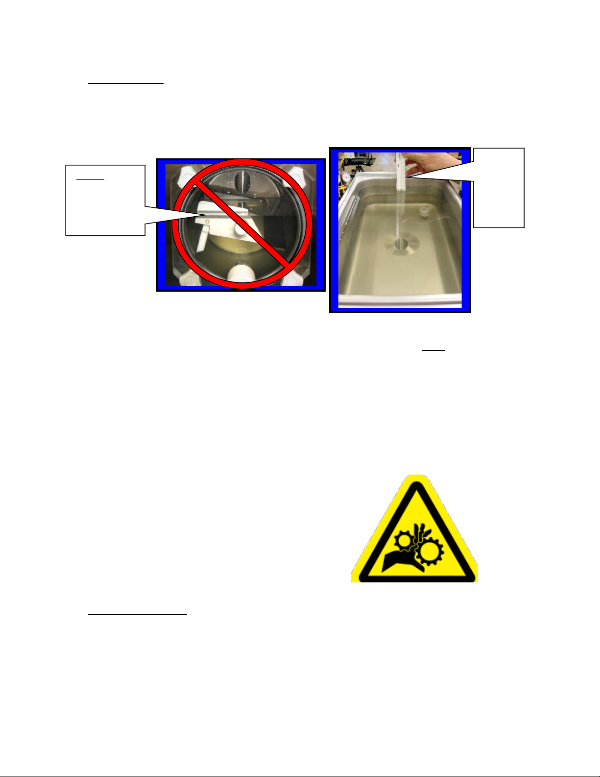
(3) Pour two gallons of cool (75ºF.) water into the hopper. Place upper switch in
“faucet” position to let the machine stir for 2 minutes. Turn machine “OFF”, drain
and dispose of the rinse water. Repeat until water is clear.
NOTICE: Do not unscrew faucet body from faceplate
to clean. (Leak free service after disturbing the Teflon
seal cannot be assured).
(5) All parts removed during the above steps plus the drip tray and insert can now be
cleaned in your warm (100ºF) cleaning solution. Rinse all parts in clean water and
allow to air-dry before re-assembly.
(6) Use cloth and cleaning solution to wipe any residue from cylinder and hopper.
(7) Re-assemble as shown in section 4.2 (next page).
(8) Mix two gallons of warm water (approximately 100ºF) with two ounces of
sanitizing powder to achieve 100 parts/million (PPM) sanitizing solution.
(9) Pour the sanitizing solution into the hopper.
(10) Place upper switch in “faucet” position. Let solution stir for 5 minutes. Turn
upper switch “OFF” (hand) position. Drain all solution.
Notice: Do not leave the solution in the machine for more than 5 minutes.
(11) Pour product into hopper. Replace hopper cover. Place both switches in right
(snowflake) position when ready to freeze product.
(4) Remove the knobs from the faceplate by turning in
a counter clockwise direction. Carefully pull the
faceplate straight away from the front of the machine.
Remove the beater bar assembly from the cylinder.
Then slide the spring seal off the rear of the beater bar.
Unscrew white faucet cap to remove faucet plunger
from faucet body. Remove all O-rings for cleaning.

11
4.2 RE-ASSEMBLY
(1) Hand wipe all surfaces to remove any
remaining residue on the machine, then: using
Petro-Gel (or other sanitary food grade lubricant),
lightly lubricate the longer end of the beater
shaft. Slide beater seal onto the shaft with the
spring end toward the beater bar. (Refer to
diagram on top of the hopper cover for correct
installation of spring seal).
NOTICE: The black carbon ring must be
facing the end of the beater bar shaft, so it
will be in direct contact with the white
ceramic seal inside the cylinder when the
beater bar is re-installed. This is a dry seal
and must be kept free of lubricants.
CAUTION: The beater seal may become
damaged if the beater shaft is not
lubricated before installation of the beater
seal.
(2) Carefully insert the beater bar (with beater
seal) into hole at the rear of the cylinder
and rotate until it fully engages into the
drive plate.
CAUTION: Do not strike the
ceramic seal with the beater bar
during installation!
(3) Lubricate the large, black, rubber, faceplate
O-ring with Petro-Gel then re-install and
press firmly into the faceplate groove for
proper fit. Re-install O-rings on faucet
(4) Re-install the faceplate on the machine.
First place the faceplate bushing onto
the beater shaft. Then slide face plate
onto the four studs. Now re-attach the
faceplate knobs and tighten evenly until
the faceplate O-ring is snug against the
cylinder. Re-install float and float clip.
CAUTION: Do not over tighten the knobs
or tighten against a beater bar that is not
fully engaged in the drive plate; Permanent
distortion to the faceplate may occur!
F0298
F0355
C6530
C6521
C6513

12
(5) Mix two gallons of warm water with one 2 oz. packet of sanitizer.
(6) Pour two gallons of solution into hopper. Clean the hopper and feed hole with a clean
sanitized brush.
(7) Place upper switch in “faucet” position. Let solution stir for 5 minutes. Turn upper
switch “OFF” (hand position), Drain all solution. (DO NOT RINSE!)
(8) Pour product into hopper. Replace hopper cover. Place both switches in right
(snowflake) position when ready to freeze product.
4.3 PREVENTATIVE MAINTENANCE
It is recommended that a maintenance schedule be followed to keep the machine clean
and operating properly.
WARNING: never attempt to repair or perform maintenance on machine until the main
electrical power has been disconnected.
A. DAILY
The exterior of the machine should be kept clean at all times to preserve the luster of
the stainless steel. A mild alkaline cleaner is recommended. Use a soft cloth or
sponge to apply the cleaner.
B. WEEKLY
(1) Check O-rings and rear seal for excessive wear and replace if necessary.
(2) Clean the drip tray and front of the machine with a soap solution.
C. MONTHLY
CAUTION: Air-cooled condensers must have proper air circulation. Failure to clean
the condenser on a regular basis will result in slow freezing and possible
serious damage that could void the warranty.
(1) Visually inspect the condenser for dirt by shining a light under the condenser.
(2) If the condenser is dirty, place a wet towel on the counter under the condenser.
(3) Using compressed air or a CO2 tank, blow out the dirt from the inside of the
condenser. Most of the dirt will cling to the wet towel.
(4) An alternative method of cleaning the condenser is to use a condenser brush and
vacuum.
NOTICE: If the condenser is not kept clean, loss of refrigeration efficiency will
result, causing extended run time or soft product consistency.
4.4 EXTENDED STORAGE
Refer to the following steps for storage of the machine over any long shutdown period:
(1) Turn the three position switch to the OFF (center) position.
(2) Disconnect (unplug) from the electrical supply source.
(3) Clean thoroughly with a warm detergent all parts that come in contact with the mix.
Rinse in clean water and dry all parts. Do not sanitize. Frozen Drink Machine parts
can be left disassembled until ready for use.
NOTICE: Do not let the cleaning solution stand in the hopper or in the cylinder during
the shutdown period.

13
4.5 TROUBLESHOOTING
1. Machine does not run when turned on.
A. Be sure that the plug is properly installed in wall outlet.
B. Be sure that the faceplate is installed
C. Check and reset circuit breaker if necessary.
D. Be sure that no other appliances are sharing the circuit.
2. Beater motor starts but compressor doesn’t start.
A. Both switches must be in the right (Snowflake) position.
B. Allow approximately one or two minutes for time delay to respond.
C. If necessary adjust TCC screw.
D. Check for operating extension cord. Use number 10 or 12 cord.
3. Mix dripping from drip tube.
A. Spring seal may be damaged, chipped, cracked or no longer smooth. Replace as required.
B. Spring seal on beater bar is dirty or improperly installed. Remove, clean and re-install spring seal
assembly according to instructions and diagram on top of the hopper cover.
C. Ceramic seal (inside the freezing cylinder) is dirty or loose. Clean ceramic seal. If loose re-install
as necessary.
4. Unit runs but product does not freeze to desired consistency.
A. Check recipe for proper amount of sugar.
B. Check tension of TCC screw, if necessary turn clockwise to increase thickness of drink.
C. Be sure that all 3 “skirts” are installed.
D. Check unit for adequate ventilation. (Do not run machine too close to any hot equipment.)
E. Check the condenser (under unit) to see if it has become clogged with lint, dust etc. Clean as
necessary.
F. Be sure that the cylinder is full of mix.
5. Fill light is on when hopper is full of product.
A. Float is installed upside down. Remove and re-install float.
B. If float is stuck, clean float and stem and re-assemble.
6. No product comes out when faucet handle is pulled while unit is running.
A. Frozen product is blocking “feed hole”. Turn machine off then clear ice plug from feed hole.
WARNING:Never place fingers in the “feed hole” as serious personal injury
may occur.
B. Mix is frozen solid. Low sugar content, product separation or cylinder not full. (Empty machine,
clean and start over.)
7. Compressor starts and stops intermittently.
A. Check to see that the fan is turning freely.
B. Check the condenser to be sure that it is not clogged with lint or dust.
C. If the on/off time is 30 seconds or longer, this is normal if product is frozen and no product has
been pulled in a while.
D. If the problem is causing the breaker to trip, call service repairman.
8. Unit continues to run when switched to stand-by.
A. Reset thermostat. (Turn all the way off then turn all the way on again.)
B. If problem remains call service repairman.

14
9. Beater bar does not turn.
A. Faceplate not installed. Install faceplate.
B. Mix is frozen solid. Low sugar content, product separation or cylinder not full.
C. Drive coupling stripped. Drive coupling needs to be replaced
D. Faulty motor. Replace motor
10. Mix turns grey or pitting metal in the freezing barrel
A. Too much chlorine in sanitizing solution: Follow directions on product package to get 100
parts/million chlorine solution. Stir this solution in the machine for 1-2 minutes only.
DO NOT ALLOW SANITIZING SOLUTION TO SIT IN THE MACHINE FOR ANY
REASON!!!! If the barrel becomes saturated with chlorine apply chlorine neutralizer as
needed to remove (obtain from swimming pool supply store).

15
4.6 REAR CYLINDER AND DRIVE ASSEMBLY PARTS LIST
Model 127.
1 2 3 4 5 6 7 8 910
Description Part Number
1. Ceramic Seal F0665
2. Bearing Spacer Block C2316
3. Coupling Bearing F0427
4. Flat Washer 5/16”
5. Nut 5/16-18
6. Drive Coupling C0907
7. Drive Motor F1210
8. Motor Shaft F1212
9. Gear Box F1211
10. Rear Support Bearing F0476

16
4.7 FACEPLATE / FAUCET ASSEMBLY
Faucet Assembly C6513.
Teflon Tape added
before installation
Lubricating
O-rings with
Petro-Gel
F0298
Installing Plunger
assembly C6513P
into faucet body
Installing faceplate C6521
onto front of Machine.
Installing
O-rings onto
plunger
F 0491
Align Faucet Assembly opening to
bottom of faceplate then tighten nut

17
4.7 FACEPLATE/FAUCET ASSEMBLY (cont.)
Face Plate/Faucet Assembly Part No.
A. Face plate assembly with magnet C6521
B. Faucet assembly with nut C6513
C. Plunger Assembly (only) C6513P
D. Faucet body (only) C6513B
Plunger Assembly C6513P
Knob O-Rings Face Plate
F0264 F0491 C6521
O-Ring
F0357
F.P. Bushing
C6522
Faucet Body Faucet Nut
C6513B F0197
*Magnet
Add Teflon Tape
*Motor Disconnect Magnet (Motor will not operate when faceplate is removed)

18
4.8 FLOAT SWITCH ASSEMBLY
1. The float switch assembly consists of: Post switch, Float , Float clip, O-Ring
and Nut.
2. There are two dots (or raised ring) on one end of the float. When assembled the
two dots or raised ring, must be on the top end of the float.
Clip
Fill Switch Assembly F0811
Raised ring must point up
Bottom of hopper Float
Hex shape for back-up wrench
O-Ring
Nut
Two wires from float switch to control circuit.
Top View of Float Switch
Two Dots or raised ring must point up.
Float Float Clip F0812
Post
4.9 THERMOSTAT ASSEMBLY
L1 To upper switch
F0401
2 pos. switch T-Stat

19
Water-Cooled Option on 127W ONLY
Water Bracket Assembly
(Exploded View)
Fitting, Water Hose
F6100
Fitting, Bulkhead Water Star Washer Nut
F6101
Frame
Bracket, (Water/Refrigeration)
F0200
1. Insert the water bulkhead fitting P.N. F6101 through the bracket hole.
2. Place the star washer over the threaded portion of the bulkhead fitting.
3. Install the nut onto the threaded portion of the bulkhead fitting.
4. Apply thread tape to the water hose fitting P.N. F6100 and install into the
bulkhead fitting.
Note: Do not over-tighten the water hose fitting.

20
Water-Cooled Option on 127W ONLY
Water Cooled System
There are two water fittings at the rear of the frame.
1. The system uses standard washing machine hoses.
2. Water-in, Water-out fittings located at rear of machine frame.
3. Scale build-up will occur in pipes when outlet temperatures rises above
95°F.
Coolant inlet temperature - Degrees F.
80 85 90 95 100 105
2hp 2 3 4 5 6 7
1hp 1 1 ½ 2 2 ½ 3 3 ½
Compressor
Horsepower
¾hp ¾ 1 1 ½ 2 2 ¼ 3
1/3hp 1/3 ½ 2/3 ¾ 1 1 1/3
Flow Rate Required –Gallons Per Minute
(Numbers in the boxes)
Note: Numbers in shaded area are for reference only. Tecumseh recommends that the
outlet temperature never exceed 95° F.
Note: Under the 80 degree column notice that the “hp number” equals the “number of
gallons per minute” shown in the box. For example; 2hp equals 2gpm and 1hp
equals 1gpm etc. At temperatures higher than 80 degrees the flow rate requirement
increases dramatically. For example; at 90 degrees the 2hp compressor requires
4gpm flow in order to maintain proper cooling.
Water flow in
shaded area, not
recommended
This manual suits for next models
1
Table of contents
Other Frosty Factory Beverage Dispenser manuals
Popular Beverage Dispenser manuals by other brands

Fizz Creations
Fizz Creations Slush Puppie Instructions for use

Grindmaster
Grindmaster PIC-3 Three Flavor Specifications

NutriChief
NutriChief Pyle PKWNARDS38 user manual

Bunn
Bunn iMIX-3S Illustrated parts catalog

Cornelius
Cornelius IDC 255 Service manual

Wilshire
Wilshire SLJ 1000-1 Installation and service manual

Grindmaster
Grindmaster PIC-5 Five Flavor Brochure & specs

Curtis
Curtis FRP500 Product features

Flavor Burst
Flavor Burst TS 80SS manual

CPS COLOR
CPS COLOR COROB D300 user manual

Northland Kitchen Appliance
Northland Kitchen Appliance Northland Kitchen Appliance Use and care guide

Grindmaster
Grindmaster PIC-1 Operator's manual