Fryette Valvulator GP/DI User manual

Valvulator®GP/DI
OWNERS MANUAL
DIRECT RECORDING AMPLIFIER
MODEL GP/DI
www.fryette.com

2
Welcome to the family!
Congratulations and thank you for choosing the FRYETTE Valvulator®GP/DI!
You are constantly searching for new sounds and new ways to improve your existing sound. We understand
the constantly evolving nature of artistic creativity and the search for the perfect sound to complement your
ever-widening musical vision. Providing the tools to help you create your own sonic signature is our primary
mission.
The Fryette Valvulator GP/DI is a genuine multi-functional One Watt Tube Amplier, created to provide real
tube amp dynamics tone and feel in a package designed to be used for direct recording, and honestly, as
many creative scenarios as you can dream up.
Built on decades of experience producing the nest all tube ampliers available, the Valvulator GP/DI is a
practical and highly functional tool that solves problems frequently encountered in live playing and recording
environments. Whether you are recording, performing live, writing, practicing, or just jamming at low volume,
the Valvulator GP/DI will surprise you with its tonal sophistication and functional exibility.
Getting familiar with the Valvulator GP/DI is easy, so don’t be terribly surprised when you nd yourself up
and running in no time. First-hand experience and real world application will yield the ultimate satisfaction of
nding your own path to comprehension and self-expression.

3
IMPORTANT SAFETY INSTRUCTIONS
This symbol warns the user of dangerous voltage levels localized within the enclosure.
This symbol advises the user to read all accompanying literature for safe operation of the unit.
XRead, retain, and follow all instructions. Heed all warnings.
XOnly connect the power supply cord to an earth grounded AC receptacle in accordance with the voltage and frequency
ratings listed under the AC input on the rear panel of this product.
XWARNING:Topreventdamage,reorshockhazard,donotexposethisunittorainormoisture.
XUnplugthepowersupplycordbeforecleaningtheunitexterior(useadampclothonly).Waituntiltheunitis
completely dry before reconnecting it to power.
XMaintain unobstructed air space behind and above the unit to allow for proper ventilation and cooling.
XThis product should be located away from heat sources such as radiators, heat registers, or other products that
produce heat.
XThisproductmaybeequippedwithapolarizedplug(onebladewiderthantheother).Thisisasafetyfeature.Ifyou
are unable to insert the plug into the outlet, contact an electrician to replace your obsolete outlet. Do not defeat the
safety purpose of this plug.
XProtect the power supply cord from being pinched or abraded.
XThe power supply cord of this product should be unplugged from the outlet when left unused for a long period of
time, or during electrical storms.
XThisproductshouldbeservicedbyqualiedservicepersonnelwhen:thepowersupplycordortheplughasbeen
damaged;orobjectshavefallen,orliquidhasbeenspilledontotheproduct;ortheproducthasbeenexposedto
rain;ortheproductdoesnotappeartooperatenormallyorexhibitsamarkedchangeinperformance;ortheproduct
has been dropped, or the enclosure damaged.
XDonotdriporsplashliquids,norplaceliquidlledcontainersontheunit.
XCAUTION:Nouserserviceablepartsinside,referservicingtoqualiedpersonnelonly.
XFRYETTE®ampliersandloudspeakersystemsarecapableofproducingveryhighsoundpressurelevelswhich
may cause temporary or permanent hearing damage. Use care when setting and adjusting volume levels during use.
XHazardous voltages may be present within the chassis even with the power switch off and power cord connected.
Therefore, disconnect the power cord from the rear panel power inlet before servicing.

4
FEATURES AND SPECIFICATIONS
The Valvulator GP/DI has many functions and most of them can be performed simultaneously! Every
output has a signal present as long as there is something plugged into the front panel Input or rear panel
Auxiliary Input and the front panel controls are set accordingly.
AllTube1-Wattamplierwithintegratedreactiveload: Powered by four dual triode tubes, the
Valvulator GP/DI delivers 1 watt or more into an 8 or 16 ohm speaker cabinet. The integrated reactive
load is engaged when no speaker cable is connected to the speaker output jack. This is ideal for silent/
direct recording, slaving to a larger amplier or practicing with headphones and creates the reactive relati-
onship between the guitar and the amplier. The Valvulator GP/DI works with you, not against you.
Broad tonal range with three tube amp voicings: The three voicings; Clean, Deliverance (old-school
crunch), and Pittbull (modern up-front detail), are coupled with the two independent gain controls and the
“More/Less” switch giving you virtually every level of performance you could hope for, from bell-like chime
to massive gain.
Fully-functioningdry-trackingandre-ampingcapability: Guitar and bass players with digital audio
workstations can use the Valvulator GP/DI’s Direct Out 1 to run an unaffected signal into a recording
interface, or add warmth and gain to an already existing track by sending a dry track into the Aux Input of
the Valvulator GP/DI for re-amping.
Proprietary analog Cab + Mic simulator with “Air” switch: Fryette’s Cab+Mic simulation creates
additional nuance to guitar tone that is typically produced by the way a speaker cabinet and a microphone
work together in a room.
Practice in silence with the headphone amp using dedicated stereo effects: The Valvulator GP/DI
sends a mono signal to the FX Send and can accept a stereo signal to the FX Returns for use with exter-
nal effects such as delays, reverbs and chorus pedals.
Practiceorrecordatlowvolumeswithaspeakercabinet: Plug the Valvulator GP/DI into an 8 or 16
ohm cabinet for a 1-watt practice amp perfect for small studio recording.

5
FRONT PANEL OVERVIEW
1. INPUT – Plug in your instrument (Guitar, Bass,
Keyboard, etc) here.
2. VOICING SWITCH – Selects voicing for
Clean, Deliverance and Pittbull proles.
3. GAIN I – Adjusts overdrive and voicing. Counter
clockwise for crisp and articulate, clockwise
for thick and saturated.
4. GAIN II – Adjusts the amount of full range
overdrive.
5. MORE/LESS SWITCH – Activates an additional
tube gain stage.
6-8 TREBLE/MIDDLE/BASS – Passive,
Interactive tone controls.
9. DEEP/TIGHT SWITCH – Sets the low frequency
response.
10. (MASTER) VOLUME – Adjusts the power
amplier saturation and master level of the
speaker and line outputs.
11. DYNAMICS – Adjusts the patented Dynamic
Sensing Circuit (SAG). For guitar, set so that
LED blinks at peak of your pick attack.
12. DYNAMICS INDICATOR LED – Indicates
intensity of signal strength or pick attack.
13. CAB + MIC IN/OUT – Engages CAB+MIC
Simulator. Disengage if using an external
cabinet simulator/IR.
14. CONTOUR – Adjusts the mid frequency beha-
vior of the speaker simulator. Center is at.
15. EMPHASIS –Adjusts the high frequency be-
havior of the speaker simulator in conjunction
with AIR/BITE switch. Center is at.
16. AIR/BITE – Selects the mic placement simula-
tion.
17. LEVEL – Adjusts the output level of the head-
phone amp and DIRECT 2 outputs.
18. POWER – Switches main AC power on or off.
1
910 11 12 13 14 15 16 17 18
2 3 4 5 6 7 8

6
IT ALL STARTS HERE
The Input Sensitivity of an amplier, commonly referred to as GAIN, determines how much overdrive and
sustain your guitar will produce. Tonal balance, which we refer to as VOICING determines how the amp
will respond to your playing style and sound with a particular guitar. The VOICING SWITCH, GAIN I, GAIN II
AND MORE/LESS SWITCH give you total control over VOICING and GAIN. These controls, in combination
with the (MASTER) VOLUME and DYNAMICS controls provide a wide spectrum of dynamic amp tones.
VOICING SWITCH gives you three amplier voicings Clean, Deliverance and Pittbull.
GAIN I (VOICING) increases the gain amount as you rotate the knob clockwise. As the gain increases,
the tonal balance is shifted from a treble and upper mid emphasis, which produces an up-front sparkling
tone, to a lower mid and bass emphasis, which produces a thick meaty tone.
GAIN II (SATURATION) increases the gain amount as you rotate the knob clockwise but with no alteration
of the tonal balance.
Different combinations of the VOICING SWITCH, GAIN I and GAIN II settings, will have a dramatic effect on
the response of the amplier and the personality of your instrument. It is easy to get familiar with the action
of these controls and you’ll be amazed with your ability to make any guitar sparkling, fat, soulful or aggressive.
The MORE / LESS switch activates or defeats a tube gain stage. Use it in conjunction with the gain con-
trols to tailor your tone as well as distortion amount. For example, set VOICING SWITCH, GAIN I, GAIN
II, MORE/LESS and (MASTER) VOLUME and DYNAMICS as shown in the illustration above and play for
a few minutes. Now set these controls as shown in the illustration below. Notice that the overall amount
of overdrive is approximately the same as it was but the tonal balance has shifted markedly from full and
warm to crisp and spanking.
Gain Setting A
Gain Setting B
As you will see, by experimenting with combinations of settings you can cover a vast amount of tonal terri-
tory before you even begin to start thinking about tone control settings.

7
FRONT PANEL FUNCTIONS
1. INPUT – This is ¼” input. Plug in your instrument (Guitar, Bass, Keyboard, etc) here.
This sends signal to the rst gain stage and rear panel DIRECT OUT 1.
GAIN SECTION
2. VOICING SWITCH – This switch adjusts the overall voicing and tonal character of the amplier.
Clean (full-range traditional clean and beyond), Deliverance (old-school crunch), and Pittbull
(modern up-front detail).
3. GAIN I – VOICING – Sets the amount of overdrive in the second gain stage. This rst gain control
also serves as a tone shaping control, counter-clockwise for crisp and articulate, clockwise for thick
and saturated.
4. GAIN II – SATURATION – Full frequency gain control. Sets the amount of overdrive in the third gain
stage. Works in conjunction with Voicing Switch and Gain I to dial in the perfect overdrive/sustain
amount for your guitar and pick-up combination.
5. MORE/LESS – This switch selects three stages or four stages of tube preamp gain depending on
the amount of overdrive required. LESS = 3 stages, MORE = 4 stages. When using stomp boxes
or active pick-ups, four stages of gain are often unnecessary and generate undesirable levels of
background noise, so the ability to defeat the additional stage is a real plus.
EQUALIZATION SECTION
6. TREBLE – Passive High frequency equalization.
7. MIDDLE – Passive Mid frequency equalization.
8. BASS – Passive Low frequency equalization.
MASTERSECTION(1-wattPOWERAMPLIFIER)
9. DEEP/TIGHT SWITCH – This sets the amount of low end pre-EQ, and power amp bass response.
10.(MASTER) VOLUME – This adjusts the power amp saturation and the master level coming out of
the speaker and line output.
NOTE: This does NOT adjust the output of the DIRECT OUT 1 or DIRECT OUT 2.
11. DYNAMICS – This adjusts the dynamic feel of the tube amplier allowing you to vary the voltage
“SAG” or natural compression of the amp. This creates the feel of playing through a big cranked
amp, pushed to its limits.
12.DYNAMICS INDICATOR LED – Indicates intensity of the signal strength. Adjust the DYNAMICS
control so that the LED blinks at the peak of your pick attack.
1
910 11 12 13 14 15 16 17 18
2 3 4 5 6 7 8

8
CAB+MIC SECTION
13.IN/OUT – This switch engages the analog CAB + MIC Simulator. You can dis-engage this section
if you are using an external Impulse Response cabinet simulator.
14.CONTOUR – This speaker curve simulation control adjusts the mid frequency behavior of the CAB
+ MIC simulator. Control range is +/- 12dB, center detent is at.
15.EMPHASIS – This microphone simulation control adjusts the high frequency behavior of the CAB +
MIC simulator in conjunction with the AIR/BITE SWITCH. Control range is +/- 12dB, center detent is
at.
16.AIR/BITE – This switch selects the type of mic and placement simulation. The AIR setting creates
a more open sound (emphasizing higher frequencies), similar to an off-axis mic placement. The
BITE setting creates a more pronounced top end, accentuating the upper-mid frequencies, similar
to an on-axis mic placement.
OUTPUT SECTION
17. LEVEL – This adjusts the output level of the headphone amp output and DIRECT 2 outputs.
NOTE: This does NOT adjust the output level of the AMPLIFIER OUT section.
POWER SECTION
18.POWER – Switches main AC power on or off.
REAR PANEL FEATURES AND FUNCTIONS
IMPEDANCE SECTION
1. IMPEDANCE SWITCH – 8 or 16 ohms. Please refer to the cabinet to determine which setting to
use. For a 4 Ohm cabinet, use the 8 Ohm setting.
1
910 11 12 13 14 15
2 3 4 5 6 7 8

9
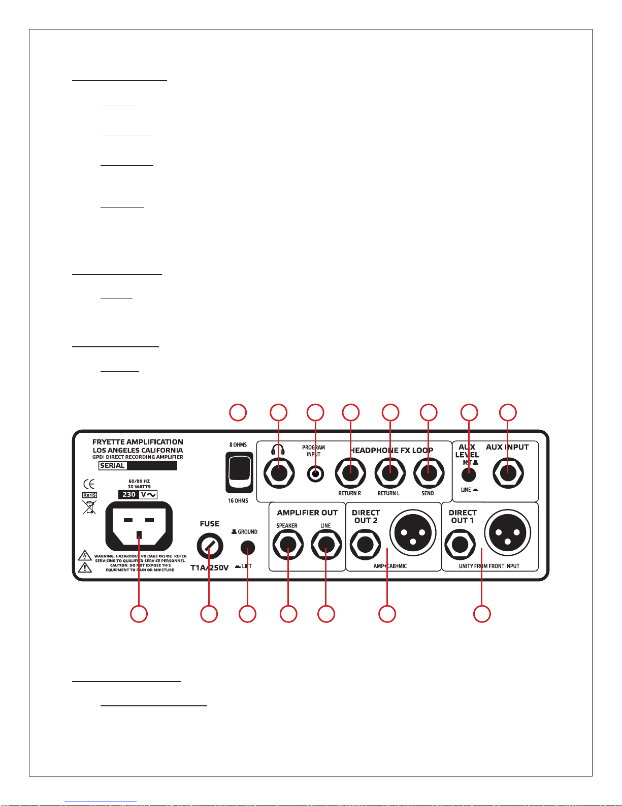
HEADPHONE FX LOOP SECTION
NOTE: This is a dedicated effects loop for the headphone amp only.
This effects loop does not feed the amplier section or direct outputs. When using the GP/DI for live
performance or direct recording, place effects before or after the GP/DI. (See the sample set up
examples in the manual).
2. HEADPHONE JACK – The headphone output is a ¼” stereo headphone output.
3. PROGRAM INPUT – This is a 3.5 mm input jack for plugging in your MP3 player, tablet, smartphone,
CD player or cassette deck. This input is unaffected by the effects loop, global eq, and cab+mic simulation.
This input can only be heard through the headphone output. The program level in the headphones
is determined by the output level control of the device being used.
4. FX RETURN R – The right side of the Headphone FX loop return input.
5. FX RETURN L – The left side of the Headphone FX loop return input.
6. SEND – Sends a buffered low impedance mono signal out to your external effects.
AUX INPUT SECTION
7. AUX LEVEL SWITCH – This switch selects Instrument Level or engages a -10 dB pad on the input
signal to accept Line Level signals.
8. AUX INPUT – Auxiliary input that can be used as a rear input for rack mounting or re-amping.
GENERAL SECTION
9. AC MAINS INPUT – Connect to a grounded outlet in accordance with the voltage and frequency
specied on the rear panel of your amplier.
10.MAINS FUSE – Protects the amplier from electrical faults. Replace only with type and rating spe-
cied on the rear panel of your amplier.
11. GROUND LIFT – This switch separates the internal circuit ground from chassis and power ground
in order to eliminate possible ground loops between the GP/DI and other equipment. Select the po-
sition which yields quietest operation. With a properly wired AC outlet and factory supplied AC cord,
this switch may not produce a noticeable difference.
AMPLIFIER OUT SECTION
12.SPEAKER OUTPUT – This is an, all-tube powered 1-Watt speaker output that can drive an 8 ohm
or 16 ohm speaker cabinet. This is just like the speaker output of a regular guitar amp head. This
signal is not affected by the FX loop or the Cab + Mic simulation.
13.LINE OUTPUT – The ¼’ unbalanced line level output can be sent to a mixing board, an external power
amp or recording interface. This signal is not affected by the FX loop or the Cab + Mic simulation.
DIRECT OUT 2 SECTION: AMP + CAB + MIC
14. This is your Amp + Cab + Mic output. The Direct Out 2 section features a ¼” unbalanced and an
XLR balanced low impedance output. This section is affected by the Cab + Mic simulation, when it
is engaged.
DIRECT OUT 1 SECTION: UNEFFECTED SIGNAL, UNITY FROM INPUT
15.This is your tube-buffered direct/re-amp signal. The Direct Out 1 section features a ¼” unbalanced
and an XLR balanced low impedance output. This section is NOT affected by any of the front panel
controls. This is designed for direct recording your raw instrument performance to be used later for
re-amping. It also serves as an excellent acoustic instrument direct box.

10
USE ONLY THE FACTORY SUPPLIED CORDSET OR A UL APPROVED EQUIVALENT TYPE
TUBE FUNCTION AND LOCATION
Preamp, phase inverter and power tubes are mounted horizontally inside the unit. No provision for internal
or external biasing is provided. For best performance, replace only with factory recommended tubes.
TO REDUCE THE RISK OF ELECTRIC SHOCK, PLEASE REFER SERVICING TO QUALIFIED
SERVICE PERSONNNEL. NO USER SERVICABLE PARTS INSIDE.
The Valvulator GP/DI tube compliment is as follows:
1 - 12AX7WB (Sovtek)
2 - 12AX7AC (Shuguang)
1 - 12DW7 (JJ) SAMPLE SETTINGS
CommunicationBreakdown
Running With The Devil
Anarchy In The UK
Bass: Clean James Brown „Cold Sweat“
(P-bass with tone control rolled-off)
Steely Dan „Peg“ (Active J-bass with
on-board tone controls set „at“)
Dig A Pony
Won‘t Get Fooled Again
Welcome To The Jungle
Bass: Overdriven King Crimson „Starless“ (P-bass)
Beastie Boys „Sabotage“ (Active J-bass)
Increase GAIN I and GAIN II to explore
high gain bass settings.

11
GP/DI APPLICATION EXAMPLES
either/or
Digital
Audio
Interface
to input on mixer
to input of
interface
optional
direct
track
(optional)
AUX INPUT
for instrument
or line level signals
Note: All controls function except the CAB+MIC section
and Level controls (which aect the Direct Out 2 for
Direct Recording)
to speaker
cabinet input
1. For Direct Recording
2.ForRecordingorPracticewithaSpeakerCabinet

12
GP/DI APPLICATION EXAMPLES
Note: All controls function. The OUTPUT section “Level”
control drives the internal headphone amp level.
L
R
REVERB
Digital eects processor
Pan Pan
4
3. For Practice with Internal Headphone Amp:
4.ForRecording(DirectplusCabinet):

13
GP/DI APPLICATION EXAMPLES
to input
on mixer
from PS2
FX loop
to PS2 FX loop
to PS2 line in
PS2 spkr out to cab in / 8 Ω
to input
on mixer
REVERB
DELAY
DELAY
Fuzz
- Integrated Reactance Amplifier -
OPE RATEVOLUME PRESENCE DEPTH
BYPAS S POWER
ON
Variable Reactive Load +Vacuum Tube Power PS-2
EDGE
FLAT
BRITE INPUT
LEVEL
DEEP
FLAT
WARM PowerStation®
PowerStation®
HI
LO
5. David Torn type setup for live performance and/or recording:

14
TROUBLESHOOTING GUIDE
SPECIFICATIONS
WON’T TURN ON
1. Make sure AC cord is securely connected at
both ends.
2. Verify the power source with something you
know works.
3. Check the mains fuse, and replace if necessary.
If it blows again, refer to qualied service personnel.
NO SOUND
1. Check input cable.
2. Check volume controls.
3. Make sure the amplier volume and/or gain
controls are turned up.
4. Check speaker cable to see if it is disconnected
or shorted.
5. Make sure that the impedance selector is fully
engaged in its detent.
6. Check the mains fuse, and replace if necessary.
If it blows again, refer to qualied service
personnel.
7. Look into the top and see if tubes are lit. If not,
refer to qualied service personnel.
8. Try replacing V4 Output Tube (12DW7).
EFFECTS NOT OPERATING
1. Make sure effects send and return cables are
good and properly connected.
EXCESSIVE HUM WHEN DIRECT RECORDING
OR SENDING DIRECT 1 OR 2 TO FRONT OF
HOUSE
1. Check Ground Lift switch.
2. Contact factory support or refer to qualied
service personnel.
EXCESSIVE DIRECT 2 OUTPUT LEVEL AND
DISTORTION
1. Contact factory support or refer to qualied
service personnel.
RUNNING HOT
1. Make sure that the unit has adequate ventilation.
2. Make sure that the fan is operating. If not, ick
the AC switch on and off a couple of times.
3. If fan cannot be made to operate, refer to
qualied service personnel.
DISTORTION
1. Check the signal level at the input and to other
devices in the signal path or in the loop.
BLOWING MAINS FUSE
1. Incorrect mains voltage internal power supply
issue. Refer to qualied service personnel.
MODEL: VALVULATOR GP/DI
MODEL NUMBER: GP/DI.
POWER REQUIREMENT: 5W
POWER AMP OUTPUT: 1W
OUTPUT IMPEDANCE: 8Ω/16Ω (selectable)
FUSE:
100V UNITS: MAINS T1.15A, 250V.
120V UNITS: T1A, 250V.
220V-240V UNITS: T0.63A, 250V.
DIMENSIONS:
HEIGHT: 3.6 in (9.1 cm)
WIDTH: 8.6 in (21.8 cm)
DEPTH: 6.2 in (15.7 cm)
WEIGHT: 5.5 lb (2.5 kg)
Product specications are subject to change without notice.

15
Certicate of Compliance
Restriction of the use of Hazardous Substances (RoHS)
We certify that all of our products (exceptions see listed below) are compliant with the European Union
Directive 2002/95/EC for the Restriction of the use of certain Hazardous Substances in Electrical and
Electronic Equipment (RoHS).
No Lead (Pb), Cadmium (Cd), Mercury (Hg), Hexavalent Chromium (Cr+6), PBB or PBDE is intentionally
added to these devices. Any trace impurities of these substances contained in the parts are below the
RoHS specied threshold levels.
All information provided in this Certicate of Compliance is accurate to the best of our knowledge as of
the date this Certication was issued.
Certicate of Compliance
Registration, Evaluation, Authorization and Restriction of chemicals (REACh)
We declare that all of our products are compliant with European Union Directive EC1907/206 for the
Registration, Evaluation, Authorization and Restriction of chemicals (REACh), and contain none or less
than 0.1% of the chemicals listed as hazardous chemicals in the REACh regulation. All information provided
in this Certicate of Compliance is accurate to the best of our knowledge as of the date this Certication
was issued.
Declaration of Conformity
EMC and Low Voltage Directive (CE)
Product Name: VALVULATOR GP/DI
Model Number: GP/DI
This is to certify that the product listed above complies with the following European Union Council Directives
and Standards relating to electromagnetic compatibility (EMC Directive 89/336/EEC) and the low voltage
Directive (73/23/EEC).
This declaration of conformity of the European Communities is the result of an examination carried out
by Electromagnetic Engineering Services, Inc. in accordance with European Standards EN 50081-1, EN
50082-1 and EN 60065 for low voltage, as laid down in Article 10 of the EMC Directive.
Fryette Amplication
6850 Vineland Ave. Unit P
North Hollywood, CA 91605 USA

16
LIMITED WARRANTY
Subject to the obligations and exclusions found below, this product is warranted by Steven Fryette Design, Inc., (herein SFD)
against manufacturing defects in materials and workmanship for the period of Five (5) Years from the date of purchase, with the
exception of the tubes, fuses and speakers where applicable, which carry a 90 day warranty.
The warranty period commences on the date of purchase by the original user. Performance under this warranty must be obtained
at one of the following: an SFD Authorized Service Station, by returning the unit to the SFD factory with prior written authorization,
or (in countries outside of the United States) by a representative SFD distributor.
Obligations
1. This warranty will be honored only on the presentation of the original proof of purchase.
2. Transportation of the product to and from an authorized SFD service outlet is the responsibility of the user. Units sent directly
to the SFD factory for warranty repairs must be authorized by SFD and shipped prepaid.
Exclusions
1. This warranty shall not cover adjustment of consumer-operated controls as explained in the appropriate instruction manual,
or products that have been altered or have missing, or defaced serial numbers.
2. This warranty shall not apply to the appearance of accessory items including but not limited to, cabinets, cabinet parts, or
knobs.
3. This warranty does not apply to uncrating, setup, installation, or the removal and reinstallation of products for repair.
4. This warranty shall not apply to repair or replacements necessitated by any cause beyond the control of SFD including, but
not limited to, any malfunction, defects, or failure caused by or resulting from unauthorized service or parts, damaged or broken
tubes, incorrect line voltage, improper maintenance, modication or repair by the user, abuse misuse, neglect, accident, re,
ood, or other Acts of God.
5. Responsibility for the repair of any SFD product sold outside of U.S. boundaries is borne by the SFD representative in that
particular country or territory. Also, the warranty term and conditions may be different from those stated above. Please contact
the SFD distributor or dealer in your country for more information.
The foregoing is in lieu of all other expressed warranties, and SFD does not authorize any party to assume for it any other obliga-
tion or liability. In no event shall SFD be liable for special or consequential damages arising from the use of this product, or for any
delay in the performance of this warranty due to causes beyond our control. Some states do not allow limitations on how long an
implied warranty lasts and/or do not allow the exclusion or limitation of consequential damages, so the above limitations on implied
warranty and consequential damages may not apply to you. This warranty gives you specic legal rights. You may have other
rights that vary from state to state.
FRYETTE AMPLIFICATION
6850 VINELAND AVE. UNIT P
NORTH HOLLYWOOD, CA 91605
TEL (818) 980-2800 FAX (818) 980-2802 www.fryette.com
Copyright 2016 Steven Fryette Design, Inc.
REVISED March 7, 2016
Table of contents
Other Fryette Amplifier manuals