Fuji Electric TK13 User manual

Thermal Overload Relays
Note!
Please give careful consideration in handling this
instruction manual and make sure that it is
delivered without fail over to the hands of the
person who takes the final responsibility for
operation and maintenance.
Type TK13
*1, *2, *3
TK25
*3
TK26
*1, *2, *3
TK26E
*3
*1:L (Long-time operating type),
Q (Quick operating type)
*2:H (Separate mounting type)
*3:A (Auto-reset type)

- 2 -
1. Introduction
Thank you for purchasing the thermal overload relays manufactured by Fuji Electric. Please confirm that the
delivered product matches your requirements including ratings and specifications. In case the product is damaged
or accessories are not included in the package, or if there is a defect in the product, please contact our nearest
sales office.
Please read this instruction manual carefully and familiarize yourself with the contents before using the product.
Please make sure that this instruction manual is delivered to the final user and is properly kept for easy access
while the product is in use. If this instruction manual is lost, you can download one from our website.
URL: http://www.fujielectric.co.jp/fcs/
2. Safety Precautions
This product must be handled by a person who has sufficient knowledge and skills to ensure safe use of the
product.
Before using the product, read this instruction manual and other attached documents to familiarize yourself with
the contents to ensure proper use of the product. Use the product only after you have gained sufficient
knowledge about the product, safety information, and relevant precautions.
After reading the documents, keep them in a place where people who use the product can access any time.
In this instruction manual, safety precautions are classified as “Warning” and “Caution”.
Indicates a potentially hazardous situation, which, if not avoided, may result in death or serious
injury.
Indicates a potentially hazardous situation, which, if not avoided, may result in minor or moderate
injury, or property damage.
It must be noted that items described in may lead to a serious result depending on situations.
Be sure to observe these precautions because every one of them is important.
The warnings and cautions described in this instruction manual are listed below.
Precautions: General
Read the instruction manual carefully before using the product so that you can
use it safely.
Warning
Do not touch the product or attempt to access the product while the power is turned ON. Otherwise, electric
shock or burn may occur.
Be sure to turn OFF the power supply before performing maintenance or inspection. Otherwise, electric
shock may occur.
Caution
When installing the product, provide a space equal to or larger than the value specified in the instruction
manual. Otherwise, burn or fire may occur.
For wiring, use wire sizes appropriate for the applied voltage and flowing current and tighten them to the
tightening torques specified in the instruction manual. Otherwise, fire may occur.
Use attached terminal screws. Due to loosening, etc., fire may occur.
Do not touch the product immediately after the power is turned OFF. Because the product is hot, you may
get burnt.
Do not modify or disassemble the product. Doing so may cause trouble.
Dispose of the product as an industrial waste.
Caution
Caution
Warning

- 3 -
Contents
1.
Introduction.........................................................................................................................................................- 2 -
2.
Safety Precautions..............................................................................................................................................- 2 -
3.
Structure, Part Name, and Manufacturing Lot Number ......................................................................................- 4 -
3.1 Structure and Part Name ..................................................................................................................................- 4 -
3.2 Type and Specifications Indication Example.....................................................................................................- 4 -
3.3 Interpretation of Manufacturing Lot Number .....................................................................................................- 4 -
4.
Unpacking...........................................................................................................................................................- 5 -
5.
Precautions in Handling, Unpacking, and Storage.............................................................................................- 5 -
6.
Mounting.............................................................................................................................................................- 5 -
7.
Wiring .................................................................................................................................................................- 6 -
8.
Usage Instructions..............................................................................................................................................- 7 -
9.
Maintenance and Inspection...............................................................................................................................- 9 -
9.1 Inspection before Operation..............................................................................................................................- 9 -
9.2 Periodical Inspection.........................................................................................................................................- 9 -
10.
Additional Information Related to UL and CSA Standards ...............................................................................- 10 -
10.1 Short circuit protective devices (SCPD)........................................................................................................- 10 -
10.2 Wiring diagram..............................................................................................................................................- 11 -

- 4 -
3. Structure, Part Name, and Manufacturing Lot Number
3.1 Structure and Part Name
Thermal overload relay
3.2 Type and Specifications Indication Example
(2) Main nameplate (type and rating)
3.3 Interpretation of Manufacturing Lot Number
Example:
3 2 01
(a) (b) (c)
(a) Last digit of the Christian year (3: Year 2013)
(b) Manufactured month (2: February)
1 … January
2 … February
:
9 … September
0 … October
X … November
Y … December
(c) Manufactured day (01: 1st)
Operating part Main nameplate
(laser printing)
Type
Rating
Manufacturing lot
number
NC contact
NO contact
Main circuit
Adjustment dial
Operating
indicator
window
Reset bar
Mounting leg

- 5 -
4. Unpacking
(1) Confirm that the type and rating match your requirements including specifications. The type is indicated on the
packing box and wrapping paper.
(2) Check if there are any missing parts or damage due to an accident during transportation.
5. Precautions in Handling, Unpacking, and Storage
(1) It is recommended that the product be used and operated immediately after unpacking. When storing the
product, pay attention to the following points.
• Carefully store the product so that it is not exposed to water (rain water, etc.) or moisture to avoid
condensation.
• Store the product in a clean place free of dust.
• Store the product in a place free of corrosive gas.
• Store the product in a packaged state and in a place where it is not exposed to high temperature, high
humidity, corrosive gases or direct sunlight.
6. Mounting
(1) Mount the product in a place where there is little humidity, dust, smoke, inflammable gas, steam, oil steam, salt,
corrosive gas, or vibration.
(2) Mount the product on a vertical plane. The allowable inclination angle is 30° or less. (Figure 6.1)
(3) Pay attention to the following points with regard to the space for mounting. (Figure 6.2)
• Provide a space of at least the value shown in the Figure below.
The dimension C is a value specified under the short-circuit breaking capacity test conditions in the IEC
standard, JIS standard, and JEM standard.
• When the products are mounted by dense side-by-side mounting, the service life of the coil may be reduced
due to temperature rise depending on the service condition (continuous current usage or dense side-by-side
mounting of products with high switching frequency).
Besides, the characteristics of thermal overload relays will slightly change due to the influence of heat
generated by heaters. When installing the products very closely to one another, they need to be separated
from one another by at least 5 mm.
Figure 6.1 Mounting Angle Figure 6.2 Minimum Mounting Space
(4) For using thermal overload relays in combination with magnetic contactors, refer to the following table.
Thermal
overload relay
Magnetic contactor to be combined
New SC Series SK Series E Series
For direct
wiring For using crimp
terminals
TK13
TK13-TN
SC-03
SC-0
SC-05 – – –
TK25 – SK18
SK22 – –
TK26
TK26-TN
SC-4-0
SC-4-1
SC-5-1 SK32 – –
TK26E – –
SC-E02
SC-E03
SC-E04
SC-E05
SC-E02P
SC-E03P
SC-E04P
SC-E05P
A
[mm] B
[mm] C
[mm]
Magnetic contactors 5 10 0
Grounding metal
B
A
B
C

- 6 -
7. Wiring
(1) Terminals can be constituted by using solid wires, twisted wire, or crimp terminals.
When using the round crimp terminal, remove the terminal cover before wiring.
(2) For connectable wire size and tightening torque, refer to Table 7.1.
Table 7.1 Connectable Wire Size and Tightening Torque
Main terminal Control and auxiliary
terminals
Type TK13 TK25, TK26 TK26E Common
Direct
connection
Solid wire [mm
2
] 1 pc. x (φ1.2 to 2)
2 pcs. x (φ1.2 to 1.6)
2 pcs. x (φ1.6 to 2)
1 pc. x (φ1.2 to 2.6)
2 pcs. x (φ1.2 to 1.6)
2 pcs. x (φ1.6 to 2)
1 pc. x (0.75 to 4)
2 pcs. x (1 to 4) 1 pc. x (φ1.2 to 2)
2 pcs. x (φ1.2 to 1.6)
2 pcs. x (φ1.6 to 2)
[AWG] 1 pc. x (16 to 12)
2 pcs. x (16 to 14)
2 pcs. x (14 to 12)
1 pc. x (16 to 10)
2 pcs. x (16 to 14)
2 pcs. x (14 to 12)
1 pc. x (18 to 12)
2 pcs. x (18 to 12)
1 pc. x (16 to 12)
2 pcs. x (16 to 14)
2 pcs. x (14 to 12)
Twisted wire [mm
2
] 1 pc. x (0.75 to 2.5)
2 pcs. x (0.75 to 1.5)
2 pcs. x (1.5 to 2.5)
1 pc. x (0.75 to 5.5)
2 pcs. x (0.75 to 1)
2 pcs. x (1 to 1.5)
2 pcs. x (1.5 to 2.5)
2 pcs. x (2.5 to 4)
1 pc. x (0.75 to 4)
2 pcs. x (1 to 4) 1 pc. x (0.75 to 2.5)
2 pcs. x (0.75 to 1.5)
2 pcs. x (1.5 to 2.5)
[AWG] 1 pc. x (18 to 14)
2 pcs. x (18 to 16)
2 pcs. x (16 to 14)
1 pc. x (18 to 10)
2 pcs. x (16 to 14)
2 pcs. x (14 to 12)
1 pc. x (18 to 12)
2 pcs. x (18 to 12)
1 pc. x (18 to 14)
2 pcs. x (18 to 16)
2 pcs. x (16 to 14)
Stripping length
[mm] 9 to 10 10 to 11 9 to 10
Flexible twisted wire
(With sleeve) [mm
2
] 1 pc. x (0.75 to 2.5)
2 pcs. x (0.75 to 1.5)
2 pcs. x (1.5 to 2.5)
1 pc. x (0.75 to 2.5)
2 pcs. x (0.75 to 1)
2 pcs. x (1 to 1.5)
2 pcs. x (1.5 to 2.5)
1 pc. x (0.75 to 4)
2 pcs. x (1 to 4) 1 pc. x (0.75 to 2.5)
2 pcs. x (0.75 to 1.5)
2 pcs. x (1.5 to 2.5)
[AWG] 1 pc. x (18 to 14)
2 pcs. x (18 to 16)
2 pcs. x (16 to 14)
1 pc. x (18 to 12)
2 pcs. x (16 to 14)
2 pcs. x (14 to 12)
1 pc. x (18 to 12)
2 pcs. x (18 to 12)
1 pc. x (18 to 14)
2 pcs. x (18 to 16)
2 pcs. x (16 to 14)
Sleeve dimension
[mm] 10 11 10
Crimp terminal
connection Twisted wire, flexible
twisted wire [mm
2
] 0.75 to 4 0.75 to 10 0.75 to 10 0.75 to 2.5
[AWG] 18 to 10 18 to 8 18 to 8 18 to 14
Maximum crimp
terminal width
[mm] 7.7 9.7 9.7 7.7
F dimension of the lower
one of the two crimp
terminals (Figure 7.1)
[mm] 7 or larger 9 or larger 9 or larger 6 or larger
Terminal screw size M3.5 M4 M3.5
Tightening tool Phillips H2 type
Flat-head screwdriver I-1 x 5.5 x L type B
Tightening torque [N•m] 0.8 to 1.0 1.2 to 1.5 0.8 to 1.0
(Note 1) The flexible twisted wires cannot be used without sleeves.
As for using sleeves, crimp the sleeve (ferrule).
Twisted wire of 0.75 to 5.5 mm
2
(18 to 10 AWG): The number of wires must be seven or less.
Flexible twisted wire: The number of wires is larger than the above.
(Note 2) Use sleeves that comply with the DIN46228 standard.
• When using wire of 1.5 to 2.5 mm
2
(16 to 14 AWG), use sleeves with no insulation sheath.
• Depending on the crimping tool, there is a case where sleeves cannot be inserted into terminals.
Use the Phoenix Contact CRIMPFOX 6 or an equivalent crimping tool.
For the wire stripping length, follow the instructions provided by the sleeve manufacturer.
(Note 3) To comply with the UL and CSA standards, use the wire size of 14 AWG or 12AWG.
And, use solid wires, twisted wires, or crimp terminals.
(Note 4) It is possible to connect two crimp terminals. (Figure 7.1) The length of wire protrusion must be
1 mm or less.
(Note 5) Tighten all the terminals including ones not wired.
(Note 6) When connected wires are bent for line arrangement after wiring, confirm again that the
tightening torque is appropriate.
Crimp terminal
Terminal plate
Figure 7.1 Connecting Two
Crimp Terminals
1 or less

- 7 -
8. Usage Instructions
(1) Mounting to and removing from the magnetic contactor
• Mount the thermal overload relay according to the following procedure. (Figure 8.1)
(a) Loosen the terminal screws for Nos. 2, 4, and 6 terminals of the magnetic contactor.
(b) Align the thermal overload relay leg with the hole in the magnetic contactor and insert it in the
direction indicated by an arrow.
(c) Insert the thermal overload relay so that the main circuit section of the thermal overload relay
comes to the right of the terminal screws of the main circuit.
(d) Tighten the terminal screws of the magnetic contactor to the specified torque. (Refer to the
instruction manual for magnetic contactors.)
• Remove the thermal overload relay according to the following procedure. (Figure 8.2)
(a) Remove all the terminal screws for Nos. 2, 4, and 6 terminals of the magnetic contactor.
(b) Remove the thermal overload relay in the direction indicated by an arrow.
Figure 8.1 Mounting to the Magnetic Contactor Figure 8.2 Removing from the Magnetic Contactor
(2) Removing the terminal cover (Figure 8.3)
Firmly hold down the thermal overload relay, insert a screwdriver or similar tool into the terminal cover, and then
move the screwdriver down as indicated by arrows.
Figure 8.3 Removing the Terminal Cover
(c)
(d)
(b)
(a)
(b)
(a)

- 8 -
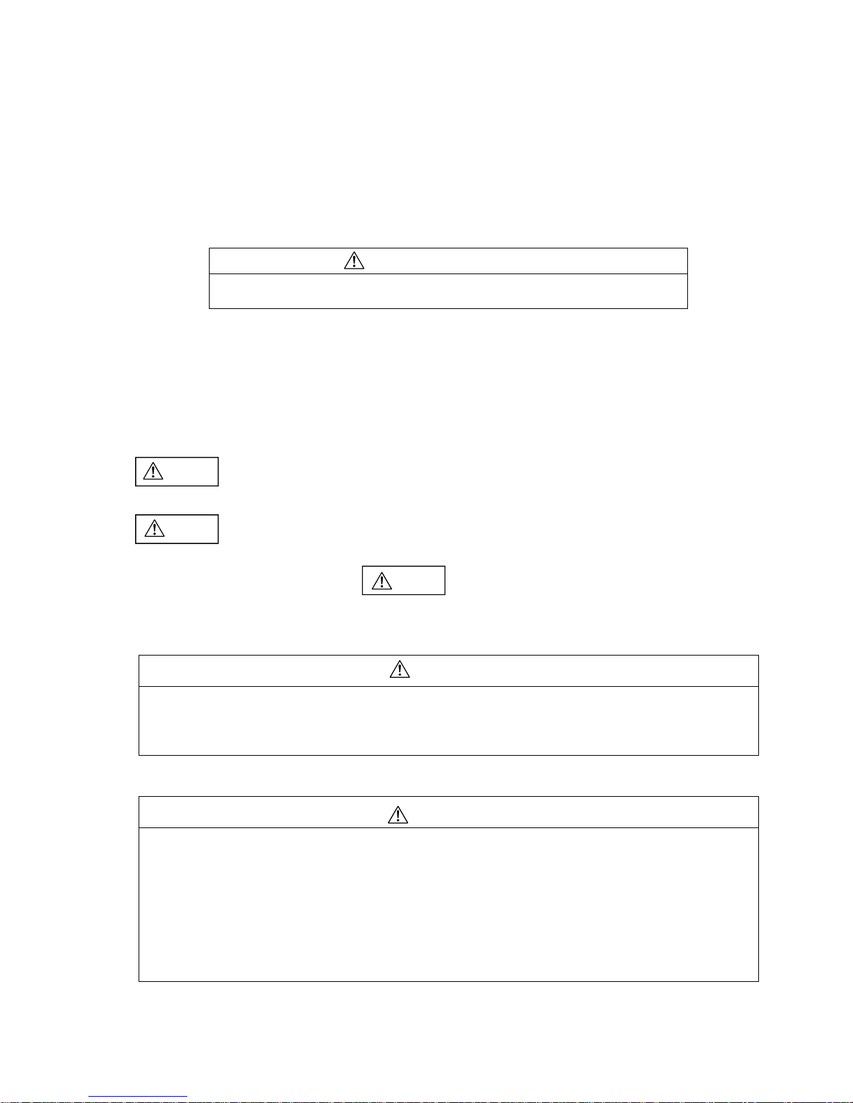
(3) Current setting method (Figure 8.4)
• Turn the adjustment dial within its scale and set the full load current of the motor to the downward triangle mark
(▼). If it is used outside the scale, the product performance will not be satisfied.
• When the inverter is used in the secondary side, a faulty tripping may be caused by leakage current. When
using the inverter, measure the current at the place where the thermal overload relay is mounted and select an
appropriate one.
• When using a serge prevention device in the secondary side of the thermal overload relay, set the current to a
value with leakage current added.
• Depending on the type of motor to be used, the thermal overload relay may make unnecessary actions at the
startup. In such a case, increase the current value set by the dial to approximately 5% or less. If it is increased
higher than that guideline, the motor may not be properly protected.
Also, select an appropriate thermal overload relay such as long-time operating type or quick operating type
depending on motor characteristics and load conditions.
(3)-1 When using as a separate mounting type
• When TK26 and TK26Q are used under the following ratings as a separate mounting type (TK26H
or TK26QH), the thermal overload relay tends to remain in a non-operation state compared with the
case when used as a magnetic starter. In such a case, correct the dial set current as shown in the
following table.
Type Rating Correction value
TK26H 16-22A Set to a value 5% lower than the dial set
value.
TK26H 20-26A Set to a value 10% lower than the dial
set value.
TK26QH 12-18A Set to a value 10% lower than the dial
set value.
(4) Operating indicator (Figure 8.4)
When the thermal overload relay operates, the white trip indicator in the operating indicator window will be
hidden.
(The white trip indicator will not be hidden when tripped in the automatic reset state.)
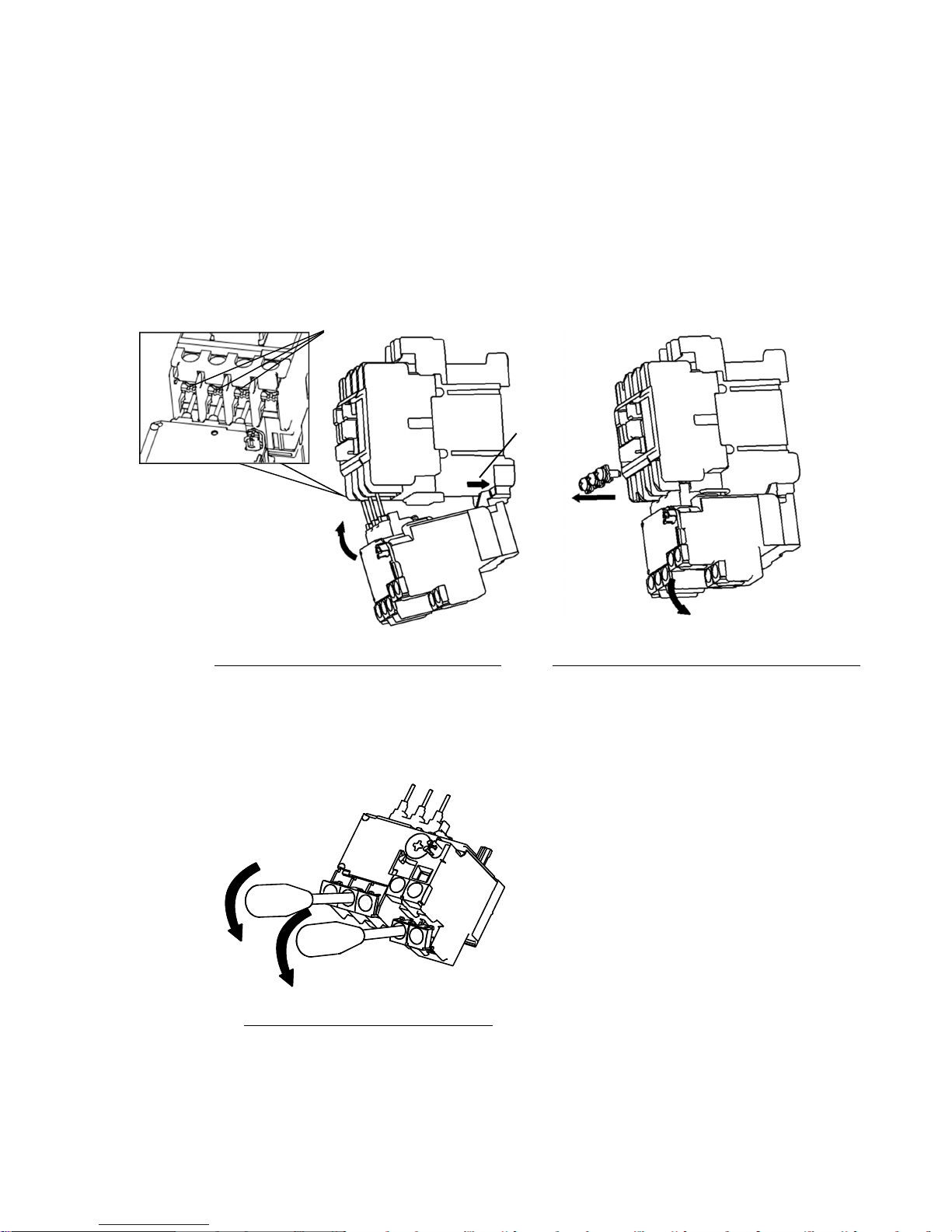
(5) Sequence checking (Figure 8.4)
Press the white trip indicator in the direction shown by an arrow to perform sequence checking.
(6) Resetting method (Figure 8.4)
When the thermal overload relay operates, first remove the cause of an error such as overload and then press
the reset bar. Press the reset bar until it comes to a stop.
(Resetting will not be possible unless the thermal overload relay is sufficiently cooled down.)
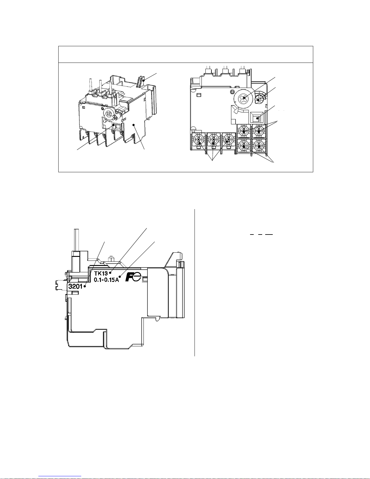
(7) Changing from manual reset to automatic reset (Figure 8.5)
Change from the manual reset to the automatic reset according to the following procedure.
Or, change from the automatic reset to the manual reset according to the reverse procedure.
(a) Open the front cover.
(b) Using a screwdriver or a similar tool, press the reset bar and turn it clockwise by 90 degrees.
(c) Confirm that the reset bar is held pushed in.
(d) Close the front cover.
Note) Attention must be paid to the fact that, in case of a two-wire control circuit, the motor is automatically
started when the thermal overload relay is automatically reset.
Figure 8.4 Current Setting, Operating Indicator, Sequence Checking, and
Resetting Figure 8.5 Changing to Automatic
Reset
リセット棒
調整ダイヤル
動作表示窓
▼マーク
リセット状態 トリップ状態
トリップ表示:白
(説明のため黒色で表記)
シーケンスチェック
④
②
③
①
リセット棒
A: Automatic reset (Automatic)
M: Manual reset (Manual)
A
M
▼mark Adjustment dial
Reset bar
Trip indicator: white
(Indicated here in black just for
explanation purposes)
Sequence checking
Reset state Tripped state
Operating indicator
window
Reset bar
(a)
(b)
(c)
(d)

- 9 -
(8) When applying to a single-phase motor or DC motor
(8)-1 Standard type (trip class of 10A) and quick operating type (trip class of 5)
The standard type relays for all ratings and the
quick operating type relays for some ratings
include phase loss protection function as
standard.
Therefore, unless power is supplied to all the
phases, the relay may operate at a value
smaller than the set current value.
When applying to a single-phase motor circuit
or to a DC circuit, perform wiring according to
either one of the wiring patterns shown in
Figure 8.6 (a) and (b).
When using the wiring pattern (b), select an
appropriate heater rating so that the current
adjustment range of the thermal overload relay
is not exceeded.
(8)-2 Long-time operating thermal overload relays
Long-time operating thermal overload relays
are exclusively for AC applications.
When using the relay for a single-phase AC
motor, wire the circuit as shown in Figure 8.7
because each phase contains a reactor and
power must be supplied to each one of those
phases.
9. Maintenance and Inspection
9.1 Inspection before Operation
(1) Check if there are any loose screws.
(2) Check if there are any wire scraps, washers, etc. are caught in the product.
(3) Check if the thermal overload relay is set to the reset state because the relay may be tripped due to vibration or
shock during transportation.
9.2 Periodical Inspection
(1) Perform the initial inspection as early as possible after starting operation. Afterwards, perform the periodical
inspection.
(2) Periodically retighten terminal tightening screws.
(3) It is recommended that the product be renewed 10 years after the manufacturing date on condition that the
product has been used under the standard usage conditions as specified in the “Report on Recommended
Renewal Timing for Low Voltage Devices” issued by Japan Electrical Manufacturers' Association (JEMA).
(a) Connect wires so that power
is supplied in series to all
polarities.
(b) Set the adjustment dial to a
value approximately 10% higher.
Figure 8.6 When Applying to a
Single-phase Motor or DC Motor
Figure 8.7 Wiring for Long-time Operating
Thermal Overload Relays

- 10 -
SCCR
[kA] Circuit
Breaker
Raiting
[A]
SCCR
[kA] Circuit
Breaker
Raiting
[A]
SCCR
[kA] Circuit
Breaker
Raiting
[A]
Fuse
Raiting
[A]
0.1-0.15
0.13-0.2
0.18-0.27
0.24-0.36
0.34-0.52
0.48-0.72
0.64-0.96
0.8-1.2
0.95-1.45
1.1-1.65
1.4-2.1
1.7-2.6
2.2-3.4
2.8-4.2
4-6
5-7.5
6-9
7-10.5
9-13 30 30
1.4-2.1
1.7-2.6
2.2-3.4
2.8-4.2
4-6
5-7.5
6-9
9-13 30 30
0.1-0.15
0.13-0.2
0.18-0.27
0.24-0.36
0.34-0.52
0.48-0.72
0.64-0.96
0.8-1.2
0.95-1.45
1.1-1.65
1.4-2.1
1.7-2.6
2.2-3.4
2.8-4.2
4-6
5-7.5
6-9
7-10.5
16-22
20-26
1.7-2.6
2.2-3.4
2.8-4.2
4-6
5-7.5
6-9
7-10.5
16-22
20-26
Overload
Relay’s
type
Contactor
Type
Heater
Element
Rating
[A]
AC240V Max. AC480V Max. AC600V Max.
TK13 SC-03
SC-0
SC-05
25 15 10 15 5 -30
20 20
SC-0
SC-05
TK13Q
SC-03
SC-0
SC-05
25 20 10 20 5 -30
SC-0
SC-05 7-10.5
TK26
TK26E SC-4-0
SC-4-1
SC-5-1
SC-E02(P)
SC-E03(P)
SC-E04(P)
SC-E05(P)
25 15 18 15 5 -30
20 20 -
50
SC-4-0
SC-4-1
SC-5-1
SC-E03(P)
SC-E04(P)
SC-E05(P)
9-13 30 30 -
SC-4-0
SC-4-1
SC-5-1
SC-E04(P)
SC-E05(P)
12-18 40 40 -
SC-E05(P) 50 50 -
TK26Q
TK26EQ SC-4-0
SC-4-1
SC-5-1
SC-E02(P)
SC-E03(P)
SC-E04(P)
SC-E05(P)
1.4-2.1 25 20 18 20 5 -30
SC-4-0
SC-4-1
SC-5-1
SC-E03(P)
SC-E04(P)
SC-E05(P)
9-13
30 30 -
SC-4-0
SC-4-1
SC-5-1
SC-E04(P)
SC-E05(P)
12-18
40 40 -50
SC-E05A
SC-E05(P) 50 50 -
SCCR
[kA] Circuit
Breaker
Raiting
[A]
SCCR
[kA] Circuit
Breaker
Raiting
[A]
SCCR
[kA] Circuit
Breaker
Raiting
[A]
Fuse
Raiti
ng
[A]
0.1-0.15
0.13-0.2
0.18-0.27
0.24-0.36
0.34-0.52
0.48-0.72
0.64-0.96
0.8-1.2
0.95-1.45
1.1-1.65
1.4-2.1
1.7-2.6
2.2-3.4
2.8-4.2
4-6
5-7.5
6-9
7-10.5
9-13 30 30 -
12-18 40/30 40/30 -
16-22
50/30
50/30
-
0.1-0.15
0.13-0.2
0.18-0.27
0.24-0.36
0.34-0.52
0.48-0.72
0.64-0.96
0.8-1.2
0.95-1.45
1.1-1.65
1.4-2.1
1.7-2.6
2.2-3.4
2.8-4.2
4-6
5-7.5
6-9
7-10.5
9-13
30 30 -
12-18
40/30 40/30 -
16-22
20-26
26-32
Overload
Relay’s
type
Contactor
Type
Heater
Element
Rating
[A]
AC240V Max. AC480V Max. AC600V Max.
TK25 SK18
SK22 35 15 35 15
10/35
25/35
5 - 30
20 20 -
-
TK26 SK32 35 15 35 15 5 -
50
30
20 20 -
25/35 10/35 50
50/30 50/30
10. Additional Information Related to UL and CSA Standards
10.1 Short circuit protective devices (SCPD)
[Note 1]
Suitable for use on a circuit capable of delivering not more
than ___kA rms symmetrical amperes, ___V max. See the
table for values.
[Note 2] WARNING:
The opening of the branch-circuit protective device may
be an indication that a fault has been interrupted. To
reduce the risk of fire or electric shock, current-carrying
parts and other components of the controller should be
examined and replaced if damaged. If burnout of the
current element of an overload relay occurs, the complete
overload relay must be replaced.
[Note 3]
The breaker or the fuse that has the rating described in
the table might not be able to be used at near the
maximum level of the permissible current for the
corresponding starter or contactor.

- 11 -
10.2 Wiring diagram
(1) 3-wire control circuit (2) 2-wire control circuit
In 2-wire control circuits, be careful of the following points when using thermal overload relay with setting reset
button to auto reset mode. If over-current flows, which is not large enough to blow the fuse or to operate the circuit
breaker, the magnetic contactor repeats make/break operations. It does this because the thermal overload relay
repeats the resets and the trips automatically. This repeated make/break operations would damage the magnetic
contactor and the thermal overload relay. Eventually, contact welding short-circuit (phase to phase) or grounding
occur, and the fuse blow or circuit breaker operate. In this case, check the magnetic contactor and the thermal
overload relay. Replace them if they have been damaged.
Master SW
by customer

This manual suits for next models
5
Table of contents
Other Fuji Electric Relay manuals