INTRODUCTION..............................................1
TESTING AND MAINTENANCE......................2
1. COMPONENT
Component ................................................. 4
Optional Accessories .................................. 5
2. EQUIPMENT
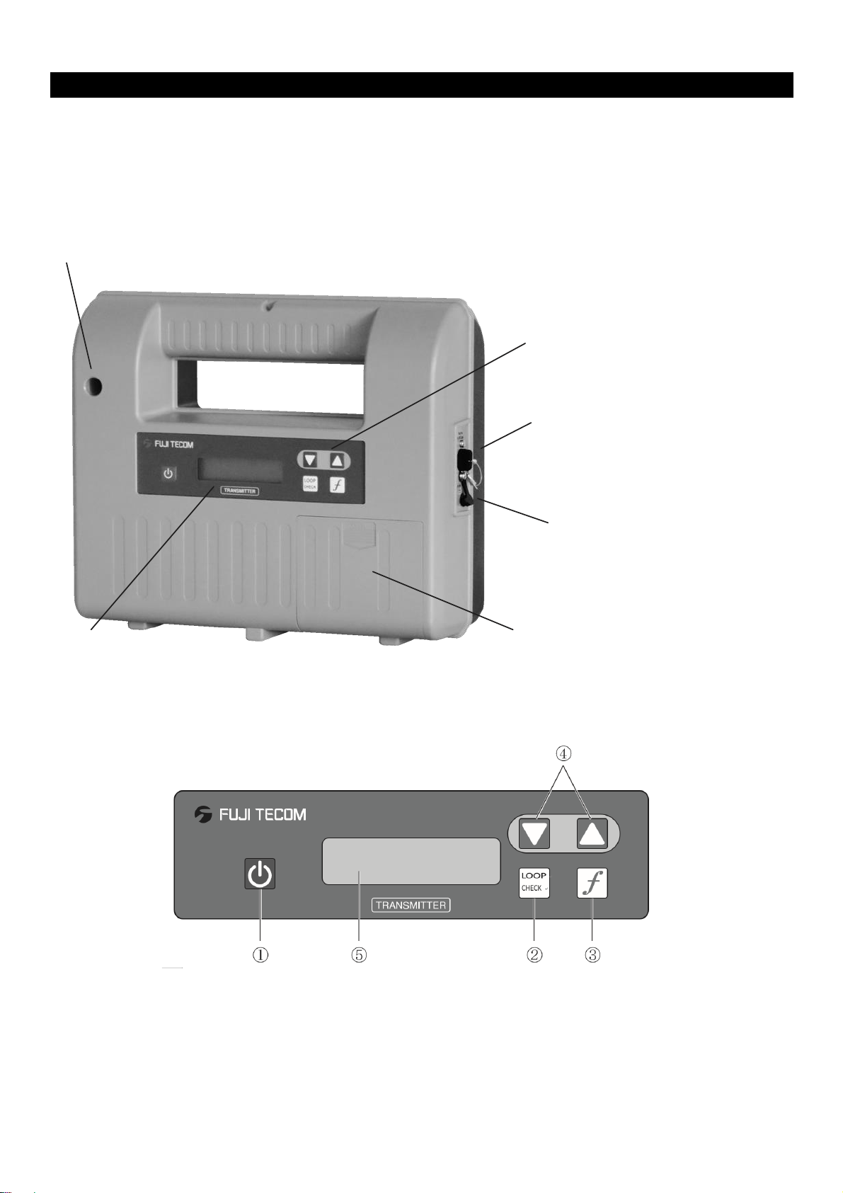
2-1 Transmitter
2-1-1 Main Unit ................................................ 6
2-1-2 Operation Panel ...................................... 6
2-1-3 Display Screen ........................................ 7
2-1-4 Replacement of Battery............................ 8
2-2 Receiver
2-2-1 Main Unit ................................................ 9
2-2-2 Operation Panel ...................................... 9
2-2-3 Display Screen ...................................... 10
2-2-4 Replacement of Battery ..........................13
3. PRINCIPLE AND USAGE
3-1 Principle of Operation .......................... 14
3-2 Proper use of Direct & Induction Mode ..... 15
3-3 Proper use of Frequency ..................... 16
3-4 How to cancel Auto Power OFF .......... 17
4. INSTALLATION OF TRANSMITTER
4-1 Direct Mode
4-1-1 Transmitter Main Unit ........................... 18
4-1-2 Installation in Loop Mode (option use).... 20
4-1-3 Detection by External Coil (option use) .. 21
4-2 Induction Mode.......................................... 22
5. OPERATION OF RECEIVER
5-1 Measurement mode & Operational procedure
5-1-1 Measurement Mode .............................. 23
5-1-2 Operational procedure of receiver.......... 23
5-2 Display screen & Measuring method of Receiver
5-2-1 Maximum & Bar & Sonde Mode............. 24
5-2-2 Pipe Axis Display.................................... 26
5-2-3 Continuous Depth Measurement............ 27
5-2-4 Pull up Measurement ............................ 28
Bluetooth Depth & Data Collection................ 29
5-2-5 Transverse Depth Measurement ............ 30
5-2-6 Detection by Sonde ............................... 31
5-2-7 Radio Mode ........................................... 32
5-2-8 AC/CP Mode ......................................... 33
6. OPERATION IN EACH SITE SITUATION
6-1 Detection by Induction Mode
6-1-1 With 2 surveyor ........................................ 34
6-1-2 With 1 surveyor ........................................ 36
6-2 Depth and current of close parallel pipes...... 37
6-3 Detection of parallel pipes in close proximity. 38
6-4 Measuring depth near end or bend of pipeline40
6-5 Confirmation of burial depth of pipeline......... 40
6-6 Detection of Elbow’s, T’s and bends in pipe.. 41
6-7 Detection of branch pipes.............................. 42
6-8 Crash barrier and curbstones are nearby...... 43
6-9 Congested pipes............................................ 44
6-10 Near electric power substation .................... 45
6-11 Near buildings ............................................ 45
6-12 Intersection ................................................ 46
6-13 Rail track side ............................................ 46
6-14 Subway passing under buried pipe.............. 47
6-15 Plumbing in factory .................................... 47
6-16 Reinforcement bars in pavement ............... 47
7. TROUBLESHOOTING ............................. 48
8. MESSAGES DISPLAY ON LCD.............. 49
9. DETECTION PERFORMANCE ............. 50
10. SPECIFICATIONS .................................... 51
11. WARRANTY ............................................... 53