Fulham FireHorse FHEX26 Instruction sheet

When using electrical equipment, including this emergency exit product, basic safety
precautions should be followed at all times, including but not limited to the following:
PLEASE READ CAREFULLY AND FOLLOW ALL INSTRUCTIONS FOR YOUR SAFETY
1. All service shall be performed by qualified service personnel. This product must be installed and
maintained in accordance with the applicable installation codes by a person familiar with the construction
operation of the product and the hazards involved.
2. This product must be installed in accordance with the applicable installation codes and ordinances.
3. Before wiring to power supply, turn off electricity at fuse or circuit breaker.
4. Disconnect A.C. power and unplug battery before servicing.
5. Consult your local building code for approved wiring and installation.
6. May be used outdoors under cover. (-10°C - 50°C / 14°F - 122°F).
7. Do not let power supply cord touch hot surfaces.
8. Do not mount near gas or electric heater.
9. Equipment should be mounted in locations and at heights where it will not readily be subjected to
tampering by unauthorized personnel.
10. The use of accessory equipment not recommended by manufacturer may cause an unsafe condition.
11. Do not use this equipment for other than intended use.
12. The AC voltage rating of this equipment is specified on the product label. Do not connect equipment
SAVE THESE INSTRUCTIONS
Page 1 of 5
20 - Rev B17 719
Fulham Co. Inc.: 12705 South Van Ness Ave., Hawthorne, CA 90250 Tel.: 1-323-779-2980 Fax.: 1-323-754-9060.
Specifications subject to change without notice.
to any other voltage.
WALL MOUNT INSTALLATION
1. Use flat head screwdriver to loosen the screws on the lens.
2. Remove lens from sign, set aside.
3. Remove EXIT stencil from housing, set aside.
4. Drill or knock out appropriate knockouts on back plate to fit junction box mounting points.
5. Drill or knock out center hole in back plate for EXIT supply wire leads.
6. Remove backing from self adhesive junction box gasket and adhere to back plate.
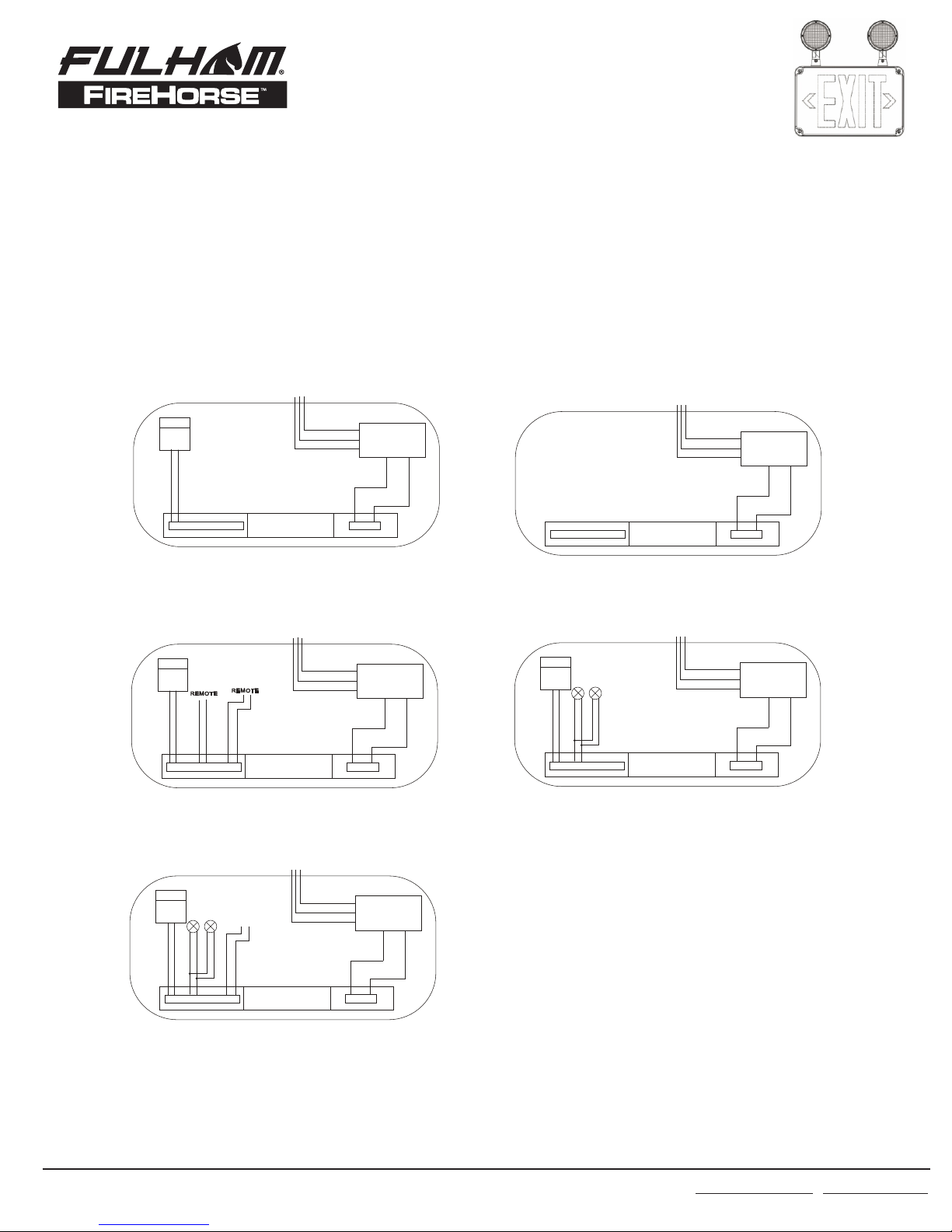
7. Route EXIT input wires through center hole of the back plate and make wiring connection.
For 120V, use black and white wires and for 277V, use red and white wires.
8. Secure back plate to junction box (hardware not included).
9. Remove proper chevron(s) as required. When removing chevrons it may be helpful to
remove the color diffuser panel to allow easier access to the chevrons. If removing color
diffuser panel it is importsnt to remember to reinstall the diffuser panel once chevron(s)
have been removed.
10. Connect battery to lamp board (battery back up models only).
11. Secure face plate(s) to the housing.
12. Secure lens to face plate and securely torque screws.
13. Apply continuous AC power and press 'TEST" button to check operation.
G
E
NERAL INSTALLATION GUIDELINES
FOR WET LOCATION EXIT FIXTURE
(FHEX26/FHEC34)

Page 2 of 5
20 - Rev B17 719
Fulham Co. Inc.: 12705 South Van Ness Ave., Hawthorne, CA 90250 Tel.: 1-323-779-2980 Fax.: 1-323-754-9060.
Specifications subject to change without notice.
1. Use flat head screwdriver to loosen the screws on the lens.
2. Remove lens, from sign, set aside.
3. Remove EXIT stencil from housing, set aside.
Drill a 3/4"hole through the desired mounting knock out located on the frame of the sign. For
ceiling mount, knock out will be located on the top of the housing. For wall mount, knock out
will be located on the side of the housing.
4. Using provided hardware, thread nut onto pipe nipple. Slide pipe nipple through canopy
center hole.
5. Remove backing from self adhesive junction box gasket and adhere to back of mounting
canopy.
Remove backing from self adhesive pipe thread gasket and adhere to front of mounting
canopy.
6. Place screws (provided) in holes on the canopy.
7. Route Exit input wires through knockout in EXIT frame, pipe nut and metal mounting plate.
8. Make wiring connection. For 120V, use black and white wires and for 277V, use red and
white wires.
WARNING: Properly insulate the unused lead with a wire nut (provided) or other approved
means.
9. Push wire connections into the J-Box. Secure mounting plate to junction box (hardware not
included).
10. Secure the canopy to the steel mounting plate with screws installed in step 7.
11. Place pipe nipple through the mounting hole of the housing until the gasket is touching the
housing frame.
Thread a second nut onto the pipe nipple on the inside of the housing to lock the canopy into
place. Once canopy is locked into position there will not be any side-to-side movement of the
canopy.
12. Remove proper chevron(s) as required. When removing chevrons it may be helpful to
remove the color diffuser panel to allow easier access to the chevrons. If removing color
diffuser panel it is important to remember to reinstall the diffuser panel once chevron(s) have
been removed.
13. Connect battery to lamp board (battery back up models only).
14. Secure face plate(s) to the housing.
15. Secure lens to face plate and securely to torque screws.
16. Apply continuous AC power and press ''Test" button to check operetion.
G
E
NERAL INSTALLATION GUIDELINES
FOR WET LOCATION EXIT FIXTURE
(FHEX26/FHEC34)

Page 3 of 5
20 - Rev B17 719
Fulham Co. Inc.: 12705 South Van Ness Ave., Hawthorne, CA 90250 Tel.: 1-323-779-2980 Fax.: 1-323-754-9060.
Specifications subject to change without notice.
CONDUIT ENTRY
1. Drill a 3/4" hole through the desired conduit entry
knock out located on the top or side of
the frame of the sign.
2. Route the AC input conduit into housing.
3. All conduit connections must use UL LISTED
and SUITABLE FOR WET LOCATION parts.
4. To finish installation of EXIT sign, reference Wall, Ceiling or End Mount instructions.
FLEXIBLE CONDUIT ONLY!
OPERATION (BATTERY BACKUP)
1. Apply AC power to the unit. The LED indicator will be RED.
2. After the battery has been left to charge for 2 hours, test the unit by pushing the
switch. The LED indicator turns OFF and the LED board stays ON.
3. When the switch is released, the LED indicator turns back to RED and the LED board
stays ON.
MAINTENANCE
Caution: Always turn off AC power to the equipment before servicing. Servicing should be
performed only by a qualified service technician. Use only MANUFACTURER supplied
replacement parts.
BATTERY: The battery supplied with the EM model requires no maintenance. However, it should
be tested periodically and replaced when it no longer operates the connected sign for the
duration of a 30-second or 90-minute test.
G
E
NERAL INSTALLATION GUIDELINES
FOR WET LOCATION EXIT FIXTURE
(FHEX26/FHEC34)

Page 4 of 5
20 - Rev B17 719
Fulham Co. Inc.: 12705 South Van Ness Ave., Hawthorne, CA 90250 Tel.: 1-323-779-2980 Fax.: 1-323-754-9060.
Specifications subject to change without notice.
The battery supplied in this sign has a life expectancy of 5 years when used in a normal ambient
temperature of 22°C / 72°F.
NFPA 101 (Life Safety Code) requires that all emergency lighting equipment be functionally tested
every 30 days for a minimum of 30 seconds and tested annually for a full 90- minute duration.
Written records of the testing are to be kept for examination by the authority having jurisdiction.
BLACK 120VAC
LED BOARD
WHITE COM
RED
BLACK
REMOTE
BAT.
RED
BLACK
RED
BLACK
D
E
R)
+
(
KC
A
L
B)
-
(
BLACK 120VAC
LED BOARD
WHITE COM
REMOTE REMOTE
3.6V/1800 mAH
BAT.
3.6V/1800 mAH
RED
BLACK
RED
BLACK
D
ER )
+
(
K
C
A
L
B)
-
(
BLUE
BLUE
BLUE
BLUE
BLUE
BLUE
BLACK 120VAC
LED BOARD
WHITE COM
BAT.
D
ER )
+
(
K
C
A
L
B)
-
(
BLACK 120VAC
LED BOARD
WHITE COM
BLACK 120VAC
LED BOARD
WHITE COM
RED
BLACK
BAT. 3.6V/1000m AH
RED
BLACK
D
ER )
+
(
K
C
A
L
B)
-
(
Exit Battery Wiring Diagram: AC Only Wiring Diagram:
Green(3.6V/500mAH)
Red(2.4V/500mAH)
Exit RC Wiring Diagram:
COMBO RC Wiring Diagram:
COMBO Wiring Diagram:
BLUE
BLUE
BLUE
BLUE
G
E
NERAL INSTALLATION GUIDELINES
FOR WET LOCATION EXIT FIXTURE
(FHEX26/FHEC34)
RED 277VAC
T R S RED 277VAC
T R S
RED 277VAC RED 277VAC
RED 277VAC
T R S T R S
T R S

ATTENTION FOR WATER PROOF INSTALLATION
1Instruction for seal ring installation
Peel off the paper
Place on the bracket
Press it to make sure it
is pasted properly
2Instruction for bracket installation
Tighten the screws
Make sure no gap between the
housing and bracket.
3 Instruction for clear lens installation
Most important is to PUSH
the middle of the lens to
balance it when tighten
the screws
push
4. Instruction for seal foam installation
Peel off the paper
Paste properly
WARNING:Press the unit to make sure it is
locked onto the wall tightely.
Distance between bracket and
wall should less than 2mm.
5.Instruction for final installation 6.Adjust the angle of the lamp head and
tighten the screws
Page 5 of 5
20 - Rev B17 719
Fulham Co. Inc.: 12705 South Van Ness Ave., Hawthorne, CA 90250 Tel.: 1-323-779-2980 Fax.: 1-323-754-9060.
Specifications subject to change without notice.
G
E
NERAL INSTALLATION GUIDELINES
FOR WET LOCATION EXIT FIXTURE
(FHEX26/FHEC34)
This manual suits for next models
1
Table of contents
Other Fulham Outdoor Light manuals

Fulham
Fulham FireHorse FHEX23 Instruction sheet

Fulham
Fulham FireHorse FHEC35 Instruction sheet

Fulham
Fulham FireHorse FHCH21 Instruction sheet

Fulham
Fulham FireHorse FHEM10WHUW Instruction sheet

Fulham
Fulham FireHorse FHEX24 Instruction sheet

Fulham
Fulham FireHorse FHEM10WHU Instruction sheet

Fulham
Fulham FireHorse FHEX21 Instruction sheet
Popular Outdoor Light manuals by other brands

GOLDENSEA UV
GOLDENSEA UV UVL150 user manual

LIGMAN
LIGMAN VK-30021 installation manual

KMART
KMART SLR-18030 instructions

DS Produkte
DS Produkte CR-4040C operating instructions

Maretti
Maretti CHIARA ROUND quick start guide

Cooper Lighting Solutions
Cooper Lighting Solutions Invue VWM Vision Wall Medium installation instructions