SET
6. INSTALLATION PROCEDURE
a)Cut the sheet where the thermostat will be fixed, with a dimension of 72 x 29 mm - Figure VII;
b)Remove the side latches (J - Figure V): for this, press the central elliptical part (with the Full Gauge
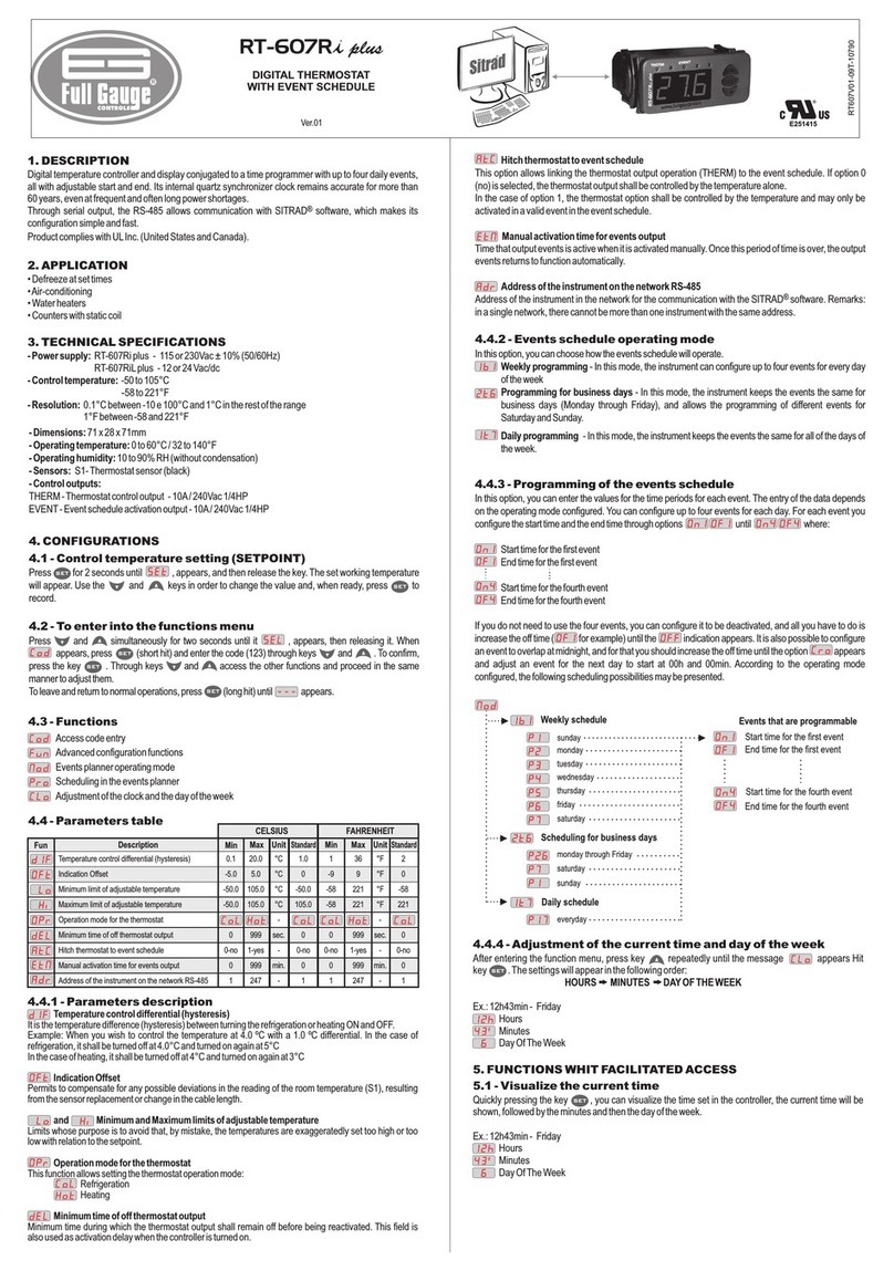
Controls logo) and slide the latch backward;
c)Insert the thermostat in the 72 x 29 mm housing socket, from the outside in;
d)Reinstall the latches (J) to fix the thermostat in the housing;
e)Do the electrical wiring as described in item 5.3;
f)Set the parameters as described in Chapter 7.
Protective vinyl (K) - Figure VI: Protects instruments installed in locations subject to splashing water, as in
commercial refrigerators.
This adhesive vinyl is with the instrument, inside the packing.
Do the application after finishing the electrical connections.
a) Remove the side latches (J);
b) Remove the protective paper;
c) Apply the vinyl (K) over the entire top, folding the flaps, as indicated by the arrows - Figure VI.
d) Reinstall the latches (J).
NOTE: The protective vinyl is transparent and does not cover the wiring diagram of the controller.
7. SET POINT AND PARAMETER SETTING
A - Led Relay
B - SET key
C - Display
D - Lower limit of operating scale
E - Upper limit of operating scale
Signs
- Led "Relay": when lit, it indicates that the NA contact (terminal "11" of the thermostat) is energized.
- When the indication appears on display, it indicates that the sensor is disconnected or the
temperature is out of the specified range.
- AHI means high temperature alarm.
- ALO means low temperature alarm.
- SOF means software, and the number that appears next to it represents the version of the controller.
7.1 Set point setting (control temperature)
Set point , or control temperature, is the right temperature to keep for a controlled environment, ie the
temperature at which the output will be disconnected.
a) Press key for 2 sec. and will appear on display. Release the key;
b) After 2 seconds, the currently set control temperature will appear;
c) Press to modify the value.
NOTE 1: For each stroke of the , key, the value increases 0.1°C until the end of the scale (105°C) or to
the maximum limit specified in the parameter setting (see item 7.2.2).
Then, the value returns to the beginning of the scale (- 50°C) or to the minimum limit specified in the
parameter setting (see item 7.2.2) .
NOTE 2: Keeping the key pressed, the value increment on display is accelerated.
d) After setting the control temperature, wait 4 sec. and the value will be recorded.
SET
SET
SET
7.2 Parameter setting
7.2.1
NOTE: Access to all parameters is protected by the access code.
For detailed information, see item 7.2.4. ‘‘Entering the access code’’.
Table of parameters
7.2.2 Parameter description
Mode of operation
Determines the mode of operation according to the purpose of the installation:
0 = cooling 1 = heating
Temperature differential (hysteresis)
It is the value of the difference in temperature to reactivate the "Relay" control output.
In other words, the difference between the Set point temperature and the temperature at which the
thermostat relay will be reactivated. The difference will be:
*Refrigeration (Operation mode ="0"): For a temperature higher than that of the Set point :
the relay on when the temperature is higher than + and off when less than .
*Heating (Operation mode ="1"): For a temperature lower than that of the set point : the relay
on when the temperature is lower than - and off when higher than .
Example (Heating): If you want to turn on the output with 30°C and turn off at 35°C. Adjust the with
"1", the Set Point with 35.0 and hysteresis with 05.0.
NOTE: The setting of a very small hysteresis results in high frequency in the thermostat relay on/off cycles
and consequently of the driven load, which may shorten the service life of these components.
Minimum delay to turn on the output
This determines the minimum time during which the output will be off. The counting of the time begins when
the output is turned off. If the output is off and you need to turn it back on right away, the relay will be triggered
only after the end of the timing adjusted to the delay. The goal is to avoid consecutive restarts of
output control.
Offset
It allows to compensate deviations in the temperature reading. Example: when changing or altering the
length of the sensor cables, it is suggested to take a detour to obtain a better response for the control in
question.
NOTE: In order to correct the deviation of the sensor reading, it is necessary to use a standard thermometer,
preferably calibrated by an approved laboratory. The driver sensor is placed alongside the standard sensor
for a few minutes for the reading to stabilize. Then, based on the reading difference between the sensors,
set the offset value in the Off Set function.
Lower limit of the set point*
Determines minimum adjustment temperature for the set point.
Upper limit of the Set point*
Determines maximum adjustment temperature for the set point.
NOTE 1*: Together, parameters and limit the thermostat control range. This scale restriction is
intended to protect the system and also safety of the application, avoiding for example, be adjusted
temperatures outside the tolerated range.
NOTE 2: The scale capacity limits of the thermostat are represented by the items in Figure IX (X - minimum)
and (Y - maximum). Respectively: -50°C and 105°C.
7.2.4 Entering the access code
The parameters setting (except set point) is protected by an access code .
To access with the code and release the setting of parameters:
a)Keep the key pressed for 10 seconds. The display will show the message ; release the key
. ;
b)After 2 seconds will show on display;
c)Press the key until appears on display.
NOTE: This operation must be performed within 4 seconds, otherwise the display will show the room
temperature. In this case, restart the procedure.
7.2.5 Setting the parameters
After entering the access code, in a maximum of 15 seconds:
a)Press the key as many times as necessary to select the desired parameter: OP, dF, dL, OF, Lo or Hi:
see the parameter description in the previous item 7.2.2;
b)After 2 seconds, the currently set value for the selected parameter will appear;
c)Press the key as many times as necessary to obtain the desired value for the parameter;
d)Wait 4 sec. and the value will be recorded: the display will return to normal operation, showing the room
temperature;
e)Do the same for the setting of all parameters.
NOTE: After entering the access code, be careful not to leave the key idle (not pressed) for more than
15 seconds between the alteration of one parameter and another. If this happens, will appear and
access to settings will be automatically blocked, requiring you to enter the 023 code again to make
alterations.
8. CONFIGURATION EXAMPLES
Case 1: Configuring the for initial fermentation or maturation of an artisanal brewer, where
the temperature should be between 17 º C (off) and 20 º C (on).
Case 2: Configuring the , used in a cold chamber to maintain the temperature between 6 and
8°C.
For these cases, make the adjustments suggested in columns "Case 1" and "Case 2" of the following table.
TIC17RGTi
TIC17RGTi
PARAMETER CASE 2
17.0
0 - COOLING
03.0
000
00.0
-50
105
06.0
0 - COOLING
02.0
000
00.0
05.0
10.0
CASE 1
SET
SET
SET
SET
SET
SET
SET
SET
SET
SET
SET
SET
FIGURE. IX
=1 =0
-50ºc 105ºc
X
ENVIRONMENTAL INFORMATION
Package:
The packages material are 100% recyclable. Just dispose it through specialized recyclers.
Products:
The electro components of Full Gauge controllers can be recycled or reused if it is
disassembled for specialized companies.
Disposal:
Do not burn or throw in domestic garbage the controllers which have reached the end-of-life.
Observe the respectively law in your region concerning the environmental responsible
manner of dispose its devices. In case of any doubts, contact Full Gauge controls for
assistance.
2013
Operation mode
Differential (hysteresis)
Minimum delay to turn on the output
Offset (local calibration)
Minimum set allowed to the final user
Maximum set allowed to the final user
0-refrig.
0.1
0
-5.0
-50
-50
1-heat.
20.0
999
5.0
105
105
-
°C
sec.
°C
°C
°C
0
2.0
0
0.0
-50
105
Description Min Max Unit Default
Fun
7.2.3 Graphical interpretation of the parameters (Figure IX )
The graph illustrates the meaning of the various parameters on the line of temperatures.
