Funk Tonstudiotechnik PAS-8 User manual

MANUAL
DIGITAL AUDIO-ROUTER

2
CONTENTS
__________________________________________________________________________________
PLEASE NOTEpage3
INTRODUCTIONpage4..5
OPERATIONpage6
AUDIO FORMATANDCONFIGURATIONpage7
INPUTCONFIGURATIONpage8
AUDIO SIGNAL QUALITY page9
POWER SUPPLYpage10
OPTIONAL VERSIONSANDACCESSORIES page10
CABLING ANDSIGNAL DISTRIBUTIONpage11..12
PIN ASSIGNMENT page9..10
BLOCKCIRCUIT DIAGRAMpage13
MEASUREMENT GRAPHS FORJITTER SPECTRUMpage14
TECHNICAL SPECIFICATIONSpage15
ELECTROMAGNETICINTERFERENCEpage16
MAINTENANCEANDREPAIRpage17
CEDECLARATIONOFCONFORMITY page18

3
PLEASE NOTE
____________________________________________________________________________________________________
This user manualonlyapplies to the PAS-8 digitalrouter with 8digitalinputs.
CAUTION:
Always connectthis deviceto a230 VAC/50..60 Hz(115 VAC/50—60 Hz) earthedpower supply.
Never connectthedeviceto anyoutletwithout aprotectiveearth contact!
Never expose thedevicetorainor moisture,asthiscreatesahazardof fire andelectricalshock.Do
notconnectthedevicetoapower supplyifithasbeendamagedmechanically,or iffluidsor objects
haveenteredintoit.Immediatelydisconnectthepower supplyintheevent of mechanicaldamageor
contactwith fluids. Onlyqualifiedservicepersonnelfollowingall applicablerulesandregulations
may openthedeviceorperformrepairs.
ENVIRONMENTAL REQUIREMENTS:
Never placethedevicenearheatsourceslikeradiators or hot-airvents. Donotexpose thedeviceto
dust, vibration, or mechanicalshocks.
CONDENSATION:
Whenthedeviceisbrought fromacoldintoawarmenvironment,water may condenseinthe
interior,andthere isariskof malfunction.Donotturnonthedeviceforthirtyminutesafter sucha
temperature changeinorder to allowthePAS-8 to assumethetemperature of theenvironment.
CLEANING:
Useasoftcloth slightlymoistenedwith amildsoapsolutionforcleaningthecasing,thefront panel,
andthecontrols. Donotuseabrasivepadsor powdersor alcoholor petroleum-basedsolventsto
cleanthedevice, as this may damagethecasingsurfaceandthecontrols.
WARRANTY:
Thisdevicehasathree-yearwarranty.Anymanufacturingor materialdefectswill berepairedfree of
chargeduringthis period. Unauthorisedopeningwill voidthewarranty!

4
PAS -8INTRODUCTION
___________________________________________________________________________________________________
DIGITAL MONITORROUTER
The PAS-8DIGITAL AUDIO SIGNAL SWITCH is aprofessional monitor router for AES/EBUsignals. Itis used to
playback,record, andmonitor digitalsignals inrecordingandvideostudios. The PAS-8 is idealfor connecting
digitalaudio devicestoAES/EBUinterfacesandvariousperipheraldevices. All inputsandoutputshaveXLRjacks
withgold-plated contacts.
ThePAS-8is notaformat converter. However, itacceptsthecommonlyusedSPDIFsignal levels. Thesignal output
is at theusual AES/EBUlevel of4Vss (peakto peak).
Thedeviceis controlledusingbuttonsonthefrontpanel. However, itcanalso beremote controlledvia AMS-2 or
MTX-MONITOR monitor systems.
Asaspecialfeature,thePAS-8offers aswitchable INSERT function.This permitsaprocessingunitconnectedto
therearXLRjackstobeloopedintothesignalchain.This functioncanbeselectedfor themonitor or therecording
channel. This for instanceallows(asshownintheexamplebelow)adigitalcompressor toberoutedintothe
monitor channelfor adjustment,thenswitchedtotherecordingchannelafteroptimisation.Afterwards themonitor
channel will befree for monitoring again.
At this configurationexampleitis possibletomakeacopyfromeverysourcetotheCD-Recorderor tothedigtal
workstation. At thesame time itis possibleto monitor another sourceindependentfromtherecording signal and to
measurethelevelofthis signal. Thedigitalcompressor is switchableintothecopysignalpathor tothemonitor
signal for testing.

5
PAS -8INTRODUCTION
_____________________________________________________________________________________________
CIRCUITRY:
Therouter'sactivecircuitryensureslowjitter, which makesthedevicesuitablefor usebeforeaD/A converterin
thesignalchain.Inordertoimprovetheoperationofasubsequentconverter, theoutputamplifiers ofthePAS-8
come withDUTYCYCLEcorrection.This ensuresaDC-free outputsignalirrespectiveofthesignallevelandduty
cycle(meantime ratio ofpositiveandnegativebits)oftheselectedsource,inadditiontoreducingpotentialjitter
caused bythelow-pass effectofaconnected line.
SYNCHRONISATION:
ThePAS-8doesnotrequireexternalsynchronisation.Iftherouteris operatedasasignalswitch inasynchronised
peripheryenvironment,thensignalswitch-overis noise-free for twoidenticallymodulatedsignal sources, as well as
for digital=0.Thesame is truefor switchoverbetweentwosignals derivedfromasinglesourcebysplitting
betweentwo matrix inputs.
Switchingbetweentwodifferentlymodulatedsignals howeverproducesacrackingnoiseduetotheleveldifference
at themomentofswitchover. This typeofswitchovernoiseis inherenttothedesignoffastswitching analogueand
digital matrices.
Thedelaybetweenswitchingoff thefirstsignalandswitchingonthenew signalis inthenanosecondrange
(10-8...10-9 s).
FRONTPANEL
MONITOR SELECT:
Twosymmetricalstereorouters (monitor andrecordingrouter)formthecoreofthe PAS-8.The MONITOR
ROUTER is used to selectthedesired monitor signal.
RECORDSELECT:
Selectingthe RECORDROUTER allowsasignaltobeselectedastherecordingsourceindependentofthesignal
source.
DIGITALINSERT:
This buttonis used to insertanexternal digital processing unitinto themonitor or recording channel.
BACKPANEL
INPUT1
INPUT2
INPUT3
INPUT4
INPUT5
INPUT6
INPUT7
INPUT8
MONITORA
INSERTRET.
MONITORBRECORD ARECORDB
FUSE50 mAt

6
PAS -8OPERATION
_____________________________________________________________________________________________________
OPERATION:
DIGITALINPUTSWITCHOVER:
Thedigital monitor signal is selected bypushing thecorresponding INPUT1..8 button. Selecting anew inputturns
off thepreviouslyselectedchannel. Inadditiontothedigitalmonitor matrix, therouteralso featuresasecond
digitalmatrix for recording. This allowsausertoselectasignalfrominputs1..8anduseitasthesourcefor a
connecteddigitalrecorder. This is independentfromthesignalthat is currentlybeingmonitored. Pressing SHIFT
andsimultaneouslyselectingadigitalsource(1..8)activatesthedigital RECORDING MATRIX androutesthe
selected signal to the recording output.
DIGITALINSERT:
The INS.MON and INS.REC areused to patch thepointofinsertioneither into
the monitor or the recording signal channel. Themonitor and recording channels
areinterlocked inorder to preventtheinsertfunctionto berouted into both
channels simultaneously. This means that beforetheinsertcanbepatched into the
monitor channel, any activerecording insertneeds to beswitched off and vice
versa.
CLOCKDISPLAY:
Thesetwo LEDs indicate thepresenceofadigital signal withavalid inputlevel at
theselected PAS-8input. For instance, ifaninputwithavalid digital signal is
selected for themonitor matrix, therelevant MON.CLK LED(green)lights up. This
also happens for non-modulated signals (digital level =0), as long as thesample
rate is present.
The REC.CLK LED(red)works similarlyfor theselected recording signal.

7
PAS -8AUDIOFORMATand CONFIGURATIONS
___________________________________________________________________________________________________
DIGITALFORMAT:
The8inputsoftherouter'stwoactivedigitalmatricesaredesignedfor AES/EBU and AES-3 formats. Theinputs
also acceptSPDIFsignals, aslongastheusuallevel(400...500 mV)is maintained. Aselectedsignalis patched
throughtotheoutput(e.g. for anexternalD/A converter)andprovided(buffered)toasecondoutput(e.g. for a
digital peakmeter). This applies bothto therecording matrix and themonitor matrix.
Theoutputformat is thesame astheinputformat;thedigitalsignalis notprocessedinany way.(Further
processingsteps likeformat conversion,signaldistributionor samplerate conversionin AES/EBU or SPDIF
format areavailableusing the DAS-SRC or the DDA-12).
ThePAS-8is fullytransparentfor all data intheserialdata stream.All usualsampleratescanbeprocessed
(including 96 kHz and 24 bitsignals).
INPUTIMPEDANCE:
All inputsandoutputsofthedigitalrouteraresymmetricalandequippedwithtransformers. Theinputimpedance
canalso beset later, separatelyfor each input,byusingjumpers. Inputimpedanceis >1 kWwiththejumperopen
and 110 Wwiththejumper closed. This makes iteasier to distribute thesignal to additional recipients.
INPUTSIGNALSPLITTING:
Inordertosendasignalnotonlytothedigitalswitch butalso toaseconddigitalrecipient,thejumperfor the
relevantinputis openedintherouter. Thesignallineis routedfromthesourcetothePAS-8first,thentothe
second recipient.
Therouteris deliveredwitha110 Ohminputterminator. For moreinformationonconfiguringthePAS-8'sinput
resistors, pleasesee the"INPUT IMPEDANCE"section.
BACKUP:
Intheeventofapowerfailureor whenthedeviceis turnedoff,thecurrentinputselectionis automaticallybacked
upinnon-volatilememory.Assoonasthepowersupplyis back online,therouterautomaticallyrestoresthestored
configuration. This also allows the PAS-8 to beoperated withatime switch.
INPUTSIGNALMONITORING:
Thedigitalrouterindicatesthepresenceofa clock for thecurrentlyselectedinputat thefrontpanel, which
facilitates quick signal tracking whenrequired. Thereareseparate indicators for themonitor and recording channel.
PAS-8combined withAMS-2orMTX-MONITOR:
IfthePAS-8is usedincombinationwithan AMS-2 or MTX-MONITOR
analoguemonitor system,thePAS-8should besuppliedwithpowervia
thesemonitor systems. Inthis configurationthePAS-8powerswitch
should leftoff inorder to ensureacentral reset bythemonitor system.
ThePAS-8hasaninternalswitchingfeaturetoadaptthestart-uptime
tothedifferentrequirementsofAMS-2andMTX-MONITOR.Start-up
time is controlledbyJumper16 inthecentreofthemainboard. This
jumperis normallyclosed(for standaloneoperationor operationwith
MTX-MONITOR). For usewiththeAMS-2, jumper 16 has to beopen.
Jumper 16

8
PAS-8 INPUTCONFIGURATION
___________________________________________________________________________________________________
CHANGING THEINPUTIMPEDANCE:
Thejumpers for inputimpedanceselectioncanbereachedbyopeningthedevicecover. Ifthejumperis onboth
contacts, inputimpedanceis 110 .Ifthejumperis ononlyonecontact,theinputimpedanceis >1 k .ThePAS-8
has 8jumpers for its 8inputs and anadditional jumper for thedigital insertinput.
Jumper for Inputimpedance1..8Jumper for insert
SPDIF SIGNALS TOBALANCEDAES/EBU INPUTS:
IfanSPDIFsignal is fed inthroughtheXLRinputs, theimpedanceat theconnected XLR
plug should beadjusted bywiring a232 Wresistor inparallel betweenpins 2and 3. This
sets theinputto acharacteristicimpedanceof75 , which is commonfor SPDIFsignals.
The"hot"wireoftheincoming lineis connected to pin2, whiletheshielding is connected
to pins 3and 1oftheXLRplug.
Pin1ontheXLRplug is leftopenifthesending deviceand thePAS-8need to be
galvanicallyseparated. Theshielding is onlyconnected to pin3inthis case.
Thefigureshows thesolder sideoftheXLRplug.
Pre-assembled adapter cables for this purposeareavailableunder thename CASA.
The CASA-T cablehas similar functions, butworks using anintegrated fastpulse
transformer, which allows itto beused withnon-standard balanced inputs (withoutan
inputtransformer).

9
AUDIOSIGNAL QUALITY
___________________________________________________________________________________________________
INPUTANDOUTPUTAMPLIFIERS
The PAS-8 is designednotonlyasarecordingsignalswitch,butprimarilyasahigh-quality monitor matrix for use
withanexternalD/A converter. Inordertoguarantee therequiredhighsignalquality,all theoutputsofthese
routers areequippedwithautomaticdutycyclepost-correction(positiveandnegativepulsewidthsarebalanced).
This keeps thebitwidth(dutycycle) moreor less constantevenfor highlydifferentinputlevels andvaryingrise
and fall times ofthesignal at theinput. Thesame applies to thePAS-8's insertchannel.
Theabovediagram illustratestheoperatingprincipleofthedutycyclecorrection.Theupper, redcurveshowsa
highlymisalignedinputsignalwithanadditionaloffset inthedutycycleof30/70 (uppermostlineofthereadings).
Thesignallevelis approx. 3.5Vss. Thelower, bluecurveshowsthePAS-8'scorrected, cleanoutputsignalwitha
symmetricaldutycycleoftypically50 %(lines2to5ofthereadings).Thediagram also showstheaccurately
defined, overshoot-free riseand fall times as well as thedelaybetweeninputand output.
All amplifierstagesareoptimisedfor minimumjitter. Thelatency betweeninputandoutputis approx. 60 ns
(nanoseconds)for themonitor channeland70 nsfor therecordingchannel. AnactiveinsertinthePAS-8adds 30
ns. Theseextremelyshortlatenciesallowthedevicetobeusedeveninhighlycomplex, synchronousstudio
systems.

10
PAS-8 POWER SUPPLY OPTIONAL VERSIONS
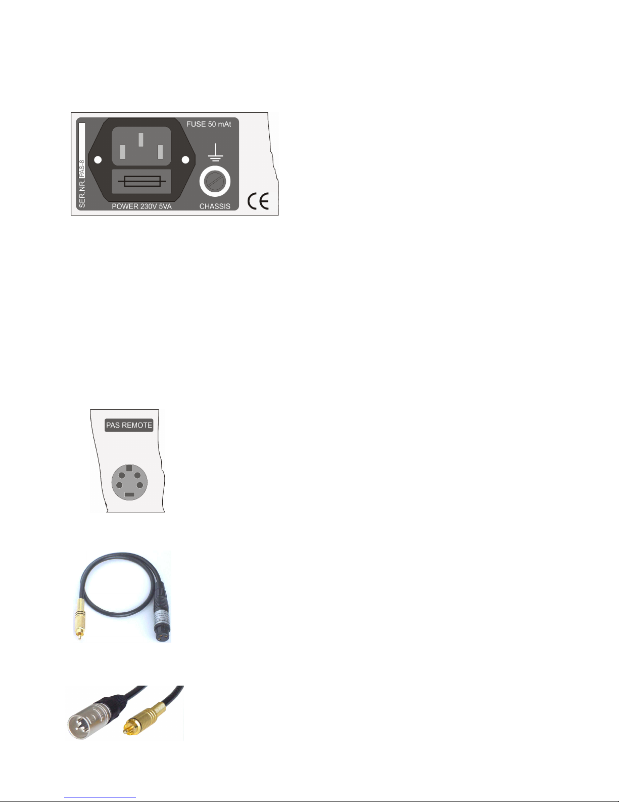
_______________________________________________________________________________
POWER SUPPLY
Protectiveearthandtechnicalearthareseparate inthe PAS-8.
This isolatestheaudio circuitsfromparasiticcurrentsinthe
19-inch rack or theprotectiveearthconductor.
Technicalearthandchassis areconnectedinternallyviaseveral
parallel0.047 µFcapacitors. This createsalow-resistance
connectionthat servesasaHFshield, whilesimultaneously
preventingtheformationofagroundloop for themains
frequency anditsharmonics. Thankstothesefeatures, the
matrix is suitablefor usewithvariousearthingstrategiesinthe
studio.
Therouterworksflawlesslyevenwhenexposedtomainsvoltagefluctuationsbetween180 and245 VAC. ThePAS-
8's stabilised supplyvoltages areshort-proofand canbemonitored bymeans ofanLEDinthefrontpanel.
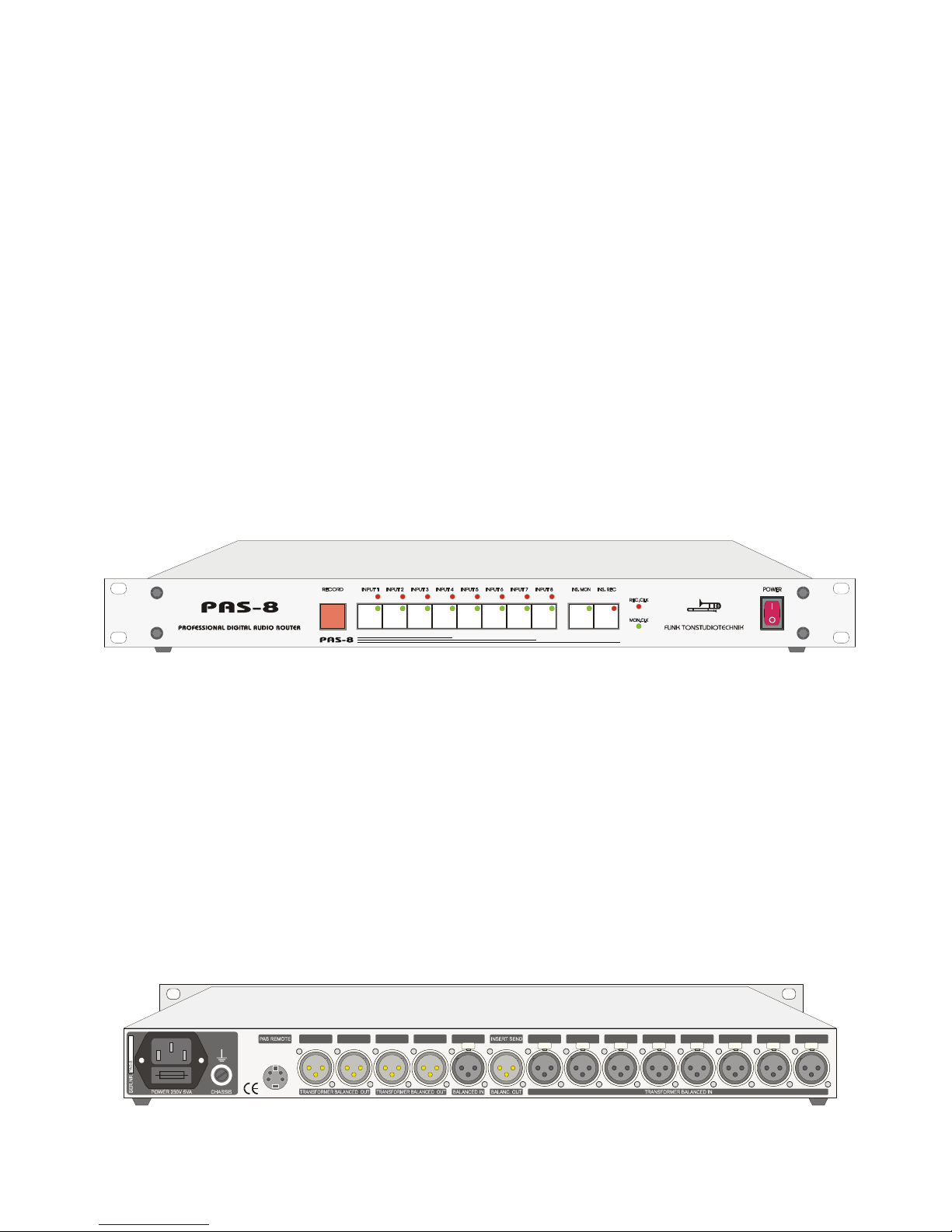
Themainsfuseis inthepowercablesocket belowthecablegland. Theductcanbepulledoutusingasmall
screwdriver. Theductalso containsasparefuse.Ifanew fuseis required, onlyusesfusesofthetype5x20 mm,
50 mA/250 V, anti-surge.
OPTIONALVERSIONSand ACCESSORIES
The PAS-8 is availableintwoversionsfor differentsupplyvoltages:230 V/50 Hz, or 115 V/50..60 Hz. Onlythe
manufacturer mayconvertthedevicefor adifferentpower supply.
ACCESSORIES–INTERFACE
Inthepack panelofthedigitalaudio routerthereis a4-poleminiDINsocket labelled
PASREMOTE.Itis usedfor connectingaserialremote controller. Theremote
controller has feedback LEDs for all functions.
This remote jack also allowsfor thePAS-8inputs to beswitched viathe AMS-2audio
monitorsystem or the MTXmonitor.Inthis casethePAS-8is suppliedwithpower
viatheMTXmonitor or theAMS-2andcanbecontrolledsimultaneouslybothat the
PAS-8itselfandfromtheanaloguemonitor systems. ThePAS-8'spowersupplyshould
beturned off (power switch)inorder to ensureacentralised reset at start-up.
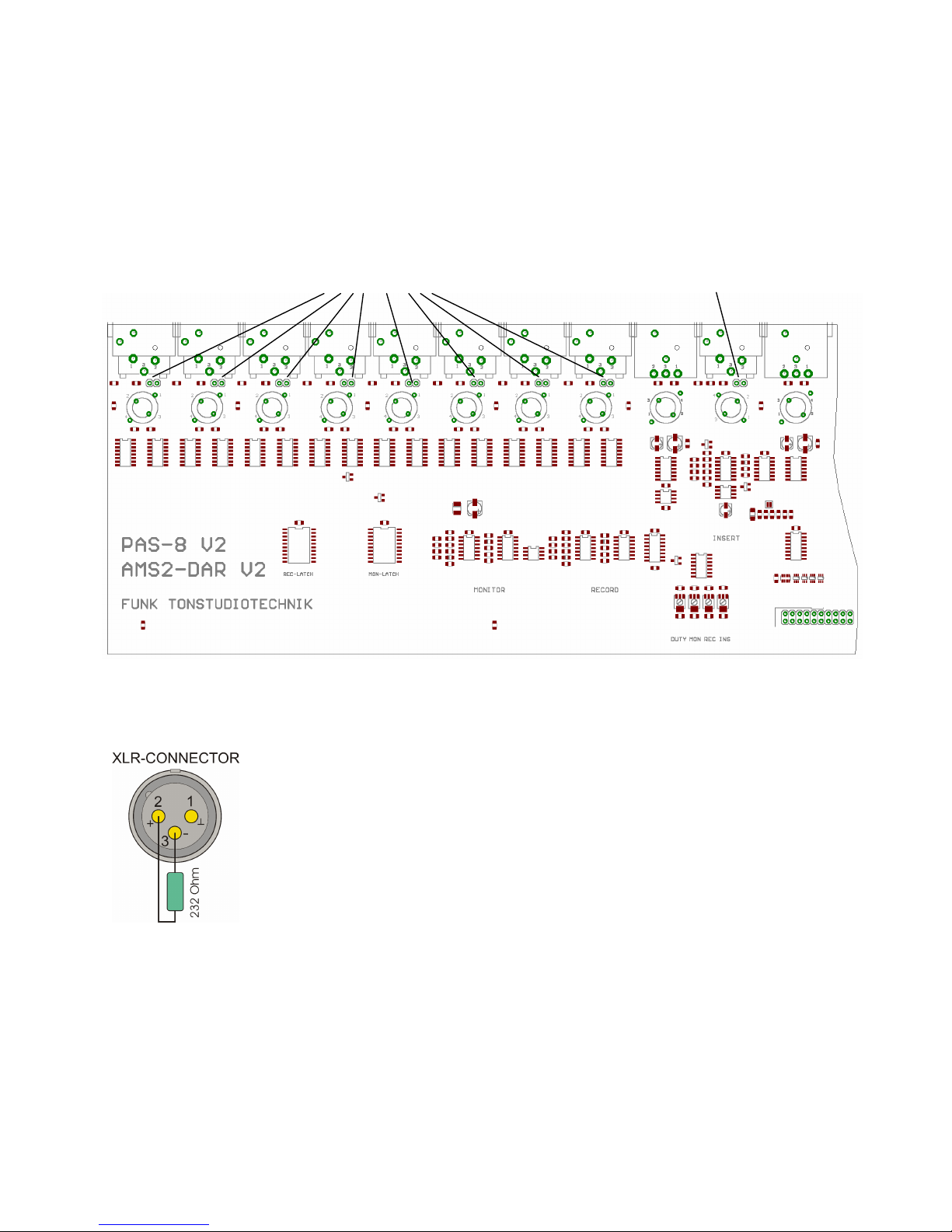
AES/EBU ÞSPDIF ADAPTER CABLE(UAS)
This cableis usedtoadaptthelevel, impedanceandbalanceofdigitalXLRoutputs,
allowingthePAS-8outputstobeconnectedtounbalancedcoaxialinputs. Levels,
balancingandimpedanceareconvertedtostandard SPDIFvalueswithoutany format
conversiontakingplace.Pleasenote that thereceivingdeviceneeds tobeableto
process thetransmittedformat.Thecableis usablefor sampleratesupto192 kHz.
Availablelengths:0.5m, 1.0m, 2.0mand 3.5m.
SPDIF ÞAES/EBU ADAPTER CABLE(CASA-T)
This cableis usedtoadapttheimpedanceandunbalanceofdigitalSPDIFoutputsto
balanced110 ΩAES/EBUInputs, allowingthePAS-8inputstobeconnectedto
unbalancedcoaxialinputs. Balancingandimpedanceareconvertedtostandard
AES/EBUvalueswithoutany format conversiontakingplace.Pleasenote that the
receivingdeviceneeds tobeabletoprocess thetransmittedformat.Thecableis
usablefor samplerates up to 192 kHz. Availablelengths:0.5, 1.0, 2.0and 3.5m.

11
PAS -8WIRING
___________________________________________________________________________________________________
CONNECTIONS
BALANCEDINPUTS:
All balancedinputsareequippedwithNEUTRIK XLRFEMALE jackswithgold-plated
contacts. Thepinassignmentis according to professional industrystandards (see figure).
Protectiveearthandtechnicalearthareseparate inthePAS-8.Topreventgroundloops
viatheinputcables(XLRpin1),pin1is notwiredtotechnicalearthinternally,buttothe
chassis viaanintermediate capacitor. This is topreventinterferencecurrentsviapin1
fromcreatingavoltagedrop overthegroundwire'sinternalresistance,which could
potentiallyinterferewiththesignal. This capacitor actsasanisolator for themains
voltagefor all practicalpurposes, whilealso functioningasalow-resistancedissipaterfor
highfrequencies.
BALANCEDOUTPUTS:
All balancedoutputsareequippedwithNEUTRIK XLRMALE jackswithgold-plated
contacts. Thepinassignmentis according to professional industrystandards (see figure).
Protectiveearthandtechnicalearthareseparate inthePAS-8.Topreventgroundloops
viatheoutputs(pin1),pin1is notwiredtotechnicalearthinternallybuttothechassis
viaanintermediate capacitor. This is topreventinterferencecurrentsviapin1from
creatingavoltagedrop overthegroundwire'sinternalresistance,which could potentially
interferewiththesignal. This capacitor actsasanisolator for themainsvoltagefor all
practicalpurposes, whilealso functioningasalow-resistancedissipaterfor high
frequencies.
SPDIF SIGNALS TOBALANCEDINPUTS:
IfanSPDIFsignalis fedinthroughtheXLRinputs, theimpedanceat theconnectedXLR
plugshould beadjustedfrom110 Wto75 Wbywiringa232 Wresistor inparallel
betweenpins2and3.The"hot"wireoftheincominglineis connectedtopin2,the
shielding is connected to pins 3and 1oftheXLRplug.
Ifthereis ariskofagroundloop formingbetweenthesendingdeviceandPAS-8,then
pin1should notbeconnected. Theshield oftheunbalancedsignalsourcewill be
terminated onpin3oftheXLRinputinthis case.
Weofferpre-madeadaptercablesofvariouslengthsasaccessories, includingimpedance
adaptationfromRCAtoXLRfor digitalaudio applications. Inthesecables, the
transmitter'sandtherecipient'searthsaregalvanicallyseparated(UAS-cableandCASA-
T-cable).This preventstheformationofagroundloop throughthis connection.The
shielding is terminated ontheRCAplug casing.
MAINSCONNECTOR IN THEBACKPANEL:
Alwaysuseapowercablewithaprotectiveearthconductor and aSchuko
plug(included)toconnectthis devicetomainspower. Achassis screw
nexttothepowerjack canbeusedtocreate alow-ohmconnectionto
therack.Ifthedeviceis used withthe AMS-2 audio monitor system, this
contactshould beconnected to thechassis jack oftheAMS-2.

12
DIGITAL ROUTER PAS-8 CONNECTIONS
____________________________________________________________________________________________________
EXAMPLECONNECTIONSFOR DIGITALRECORDING CHANNELS
Thedrawingbelowshowsanexampleconnectionfor recordingsignals (recordingmatrix).SinceAES/EBUsignals
cannotsimplybedistributedtoseveralrecipientsinparallel, theuseofanAES/EBUdistributionamplifieris
recommendedfor morethan4digitalrecipients. As anexample, thefollowing figureillustrates theuseofaDDA-12
distributionamplifier inconjunctionwiththePAS-8.
This configurationallowsany recipienttorecord signals fromany source.TheswitchingoptionsoftheDDA-12
permitthesignaltoberoutedtoinput2oftheDDA-12 insteadoftheD/A converteror thedigitalpeakmeter.
Eitherthemonitor or therecordingsignalcanbeusedasthesource.Moreover, itis possibletosendboththe
monitor and recoding signals simultaneouslyto differentrecipients for recording.
PAS-8
DDA-12

13
PAS-8 BLOCK DIAGRAM

14
PAS-8 TECHNICAL APPENDIX
____________________________________________________________________________________________________________________________________________________________________
JITTERANALYSES:
Small time offsets(jitter)ofindividualflanksarethemaincauseofqualitydegradationindigitalaudio signal
transmission. High-qualitytransmissionthereforerequires areductionofthejitter to aminimum.
Therouter'sactivecircuitryensureslowjitter, which makesthedevicehighlysuitablefor usebeforeaD/A
converterinthesignalchain.TheadditionalDUTYCYCLEcorrectionensures aDC-free outputsignal irrespective
ofsignallevels anddutycycle(meantime ratio ofpositiveandnegativebits)oftheselectedsource,inaddition
toreducingpotentialjittercausedbythelow-pass effectofaconnectedcable.Thefiguresbelowshowjitter
measurements for thePAS-8and theAMS-2DARand illustrate theextremelylowjitter inthesignal processing.
Fig. 1:
Themeasurementrecord ontheleftshowsthejitterspectrum
ofthetestingdevice(Rhode&Schwarz UPL).All
measurementrecords arescaledidentically.Theevaluated
measurementrangeis fromafew Hz up to 120 kHz.
Fig. 2:
Measurementat thePAS-8monitor output.Despite the
measuringdevice'sextremelyhighresolution,itshowsthat
thereis hardlyany increaseofjitteracross theentire
spectrum.All readings areveryclosetothesensitivitylimitof
themeasuringdevice.Thehighestrecordedjitteris at approx.
1nanosecond, andeffectivejitteris below300 ps (10-12
seconds!). Signal inputwas at input1.
Fig. 3:
Measurementat thePAS-8monitor output,signalinputat
insertreturn.Despite themeasuringdevice'sextremelyhigh
resolution,ithardlyshowsany increaseofjitteracross the
wholespectrumcomparedwithfig. 1.Again,rmsjitteris
below300 ps.
Thehighestrecorded peakjitter is at approx. 1nanosecond
(10-12 seconds!).
Fig. 4:
Measurementat themonitor outputofthePAS-8.Audio signal
inputwasviainput1at asamplerate of96 kHz andalevelof
approx. 4Vss. All AES/EBUcableshavelengthsofapprox.
2m.Rmsjitteris below150 ps. Thehighestrecordedpeak
jitter is at approx. 420 ps.

15
TECHNICAL SPECIFICATIONS PAS-8
__________________________________________________________________________________________________________________
Number ofinputs:......................................... 8Inputs 1Insert return
Number ofoutputs: ...................................... 2Monitor2Record 1Insert send
Connectorinputs: .......................................... XLRfemale gold-plated contacts
Connectoroutputs:........................................ XLRmale gold-plated contacts
Digitalformat: .............................................. AES/EBU /AES-3[alsoSPDIF with adapterplug](transparent forall formats)
Samplingfrequency:..................................... depends frominput signal(25...105 kHz)
Inputvoltagerange:..................................... 300 mV...5Vpp
Inputimpedance: .......................................... 110 Ω(1kΩwithout internaljumpers)transformerbalanced,free ofground
Common modeinputvoltage,max.: ............ ±60V
Outputvoltagel:............................................. 4,0Vpp at110 Ω
Outputimpedance: ........................................ 110 Ωtransformerbalanced,free ofearth
Common modeoutputvoltage,max.:.......... ±60V
Rise time : ...................................................... 20 ns
Delaytime input-output:.............................. 60...80 ns
Synchronisation :........................................... externalsynchronisationis notrequired
Remotecontrolformat:................................ seriell balanced,likewise RS422
Power supply: ............................................... 230 V/50...60 Hz(115 V/60 Hzoptional)
Power consumption :..................................... 3VA
Fuse :.............................................................. 50 mAt/250V5x20 mm
Protection class : ........................................... 1
Case: .............................................................. steel,light grey Front panel:aluminium,light grey (RAL 7035)
Dimensions: .................................................. 483 mm x250 mm x44 mm (width xdepht xheight)
Warranty :...................................................... 3years
Do notconnectsignals withlevels above10 Vpp to theinputs, as theymaydamagethedevice.

16
ELECTROMAGNETIC INTERFERENCE
____________________________________________________________________________________________________
ELECTROMAGNETIC INTERFERENCEand EMC
This devicecomplies withtheEMC requirements as defined inthedirectives 89/336/EEC and FCC part15:
Thedevice'selectromagneticemissionsaresufficientlylowtonotinterferewiththeintendeduseofotherdevices
and systems.
Thedeviceis sufficientlyresistantto electromagneticinterferencefor its intended use.
Thedevicehas beentested and fulfils therequirements below:
Safety: Protectionacc. to EN60950; 1992 +A1/A2; 1993 (UL1950)
EMC:Audio, video, audio-visual and
entertainmentlighting control apparatus for professional use.
Interference:EN55103-1
Immunity: EN55103-2
Compliancewiththesestandards ensuresprotectionoftheenvironmentandimmunityofthedeviceat reasonable
levels. However, itcannotbeguaranteedabsolutelythat nonegativeeffectsduetoelectromagneticinterference
occur during theoperationofthedevice.
Thefollowingmeasuresshould betakentoreducethelikelihood ofelectromagneticinterferenceasmuch as
possible:
Observetheinformationinthis user manual wheninstalling thedevice.
Useshieldedcablesfor all audio channels (XLRconnectors).Ensureproper, corrosion-resistantconnectionswitha
largesurfacebetweentheshieldingandtheconnector casing. Cableshieldingterminatedononlyoneendmayact
as atransmitter or receiver antenna.
Inyoursystem andintheoperatingenvironment,useonlycomponents(equipment,devices)that arethemselves
compliantwiththeabovestandards.
Provideanearthingstrategythat accountsfor bothsafetyrequirementsandEMC aspects. Carefullyweighthe
benefits and disadvantages ofusing astar ground, aground planeor acombined strategy.
Becarefultopreventtheformationofcurrentloops andreducetheir unwantedeffectsbykeepingtheir area as
small as possible(avoid unnecessarilylong cables)and reducing any currents byadding acommonmodechoke.

17
MAINTENANCE AND REPAIR
____________________________________________________________________________________________________
SAFETY
Onlyqualifiedservicepersonnelfollowingall applicablerulesandregulationsmayperformany workinsidethe
device.
Turnoff thedeviceand disconnectthepower supplybeforeremoving any partofthehousing.
Whenperformingmaintenanceworkonanopendeviceundermainsvoltage,becarefulnottocontactany bare
parts ofthecircuitor metal semiconductor housings either directlyor withanon-insulated tool.
Onlyusesparepartsapprovedbythemanufacturerfor themaintenanceandrepair ofsafety-relevantpartsofthe
device.
ELECTROSTATIC DISCHARGE (ESD)
Integratedcircuitsandothersemiconductors aresensitivetoelectrostaticdischarge(ESD).Improperhandlingof
assembliescontainingsuch componentsduringmaintenanceandrepair maydegradethefunctionalcharacteristics
and servicelifeofsuch parts or causefailure.
Always observethefollowing rules whenhandling components sensitiveto ESD:
Components sensitiveto ESD mayonlybestored or shipped indedicated, designated packaging.
Any handlingofESD-sensitivecomponentsoutsideoftheir packaginghastotakeplaceinelectrostatic-protected
areas(EPA,e.g. area for field serviceor arepair andserviceworkshop).Personshandlingsuch componentsmust
beconnectedtotheEPA'sgroundpotential. Thedevicetobeservicedor repaired, aswell asany tools, aids and
EPA-compliant(semi-conducting)tablematsor floor matsmustalso beconnectedtometallicsurfacesinorderto
preventESD.
Topreventany exposureofthecomponentstotransientsanddamagebyexcessivevoltageor equalisation
currents, alwaysturnoff thedeviceanddissipate any capacitor chargesbeforemakingor breakingelectrical
connections.

18
PLEASE NOTE
____________________________________________________________________________________________
CE DECLARATION OF CONFORMITY
FUNKTONSTUDIOTECHNIK10997 BERLIN
hereby declaresandwarrantsthat the product
PAS-8
is compliant withthe followingstandards accordingtoEUDirectivesandtheir
amendments:
Safety:
Protectionacc.toEN60950;1992 +A1/A2;1993 (UL1950)
EMC:
EN55103-1 EN55103-2
EvaluationcriterionB,electromagneticenvironment E4
Berlin,12 Jan 2011
Th. Funk, owner

19
Table of contents
Popular Network Router manuals by other brands

Shenzhen Hongdian Technologies
Shenzhen Hongdian Technologies Galaxy Mobile Router H7920 user manual

Inteno
Inteno EX400 installation guide

NETGEAR
NETGEAR DG834GT - 108 Mbps Super G Wireless ADSL... Reference manual

Linksys
Linksys EA5800 user guide

ZyXEL Communications
ZyXEL Communications P-335 Plus datasheet

Nortel
Nortel BayStack 100 Series Quick install guide