Furuno LAN COAX CONV KIT User manual

A
A
B
LAN COAX CONV KIT INSTALLATION INSTRUCTIONS
LAN ٭ỿἕἚӕ˄ᙲ
For OP20-47/OP20-48
The LAN COAX CONV KIT for the Junction Box and antenna allows you to use the existing coaxial cables on
your vessel. For details regarding the contents of each kit, see the packing list (included in each kit).
ˌɦỉዓረဇểᆰɶዴᢿဇỉ2ếỉ LAN٭ỿἕἚửဇẴỦẮểỂẆ ᑔỆଏ܍ỉӷ᠆ἃὊἨἽửဇẴỦẮểầỂẨ
ộẴẇ ỿἕἚỂૅዅẰủỦᢿԼỆếẟềỊẆ ӷẰủềẟỦἣἕỿὅἂἼἋἚửӋༀẲềẪẻẰẟẇ
LAN COAX CONV KIT/LAN ٭ỿἕἚ
Type/ ࡸ Code/ ἅὊἛ Remarks/ ͳᎋ
OP20-47 001-516-110 For SC-701 Junction Box/ ዓረဇ
OP20-48 001-516-120 For SC-703/SC-1303 Antenna Unit/ ᆰɶዴᢿဇ
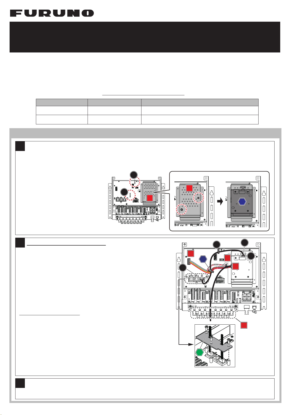
Installation for OP20-47 (For SC-701/ ዓረဇӕ˄Ậ )
Unfasten the 4 screws on the SC-701 cover, then remove the cover. Fit the two wire saddles (included) to the locations
indicated as “A”. Loosely thread the two binding screws (included) to the circled locations on the TB_PWR board cover
(indicated as “B”). Fit the LAN COAX CONV KIT to the screws, then tighten the two screws from the access holes on the
top-side of the kit (indicated as “C”).
ዓረɥ᩿ỉᵒஜỉἊửٳẲềἧἑử
ẬẆἿἕỿὅἂὁỶἶἇἛἽίӷὸửᵐ
ᵆᵟᵇỆӕ˄ẬộẴẇᵲᵠᵽᵮᵵᵰؕெίᵠὸɥỉ
ᵐỆἢỶὅἛݱἊίӷὸửዼẪӕ˄Ậ
ộẴẇᵲᵠᵽᵮᵵᵰؕெɥỆᵪᵟᵬᵽᵡᵬᵴኵԼίᵡὸ
ử᠍ẶềẆᵐỉᆭẦỤἢỶὅἛݱἊử
ዸỜộẴẇ
ዓረỉἧἑửẲềẆɥ᩿ỆᵒஜỉἊửഥỜềܭẲộẴẇ
Connecting the LAN COAX CONV KIT
Part A: Connect between the LAN CONV KIT (indicated as “A”) and the
J3 port (“A2”), using the LAN cable. Note that the supplied cable bush must
be attached to the cable at the LAN CONV KIT end. The LAN cable must be
passed through wire saddles “A1” and “C”. After the LAN connection,
secure the LAN cable to the cable clamp of the LAN CONV KIT (“A3”) using
a cable tie, and attach the securing plate* (“D”) to the J3 port.
*:The securing plate is preattached on the LAN ports (J1 to J3).
Part B: Pass the wire harnesses (indicated as “B”) through locking saddle
“C”, then connect the harnesses to their connectors (indicated as “B1”).
Pass the coaxial cable through an unused cable entry (indicated as “B2”),
then secure the coaxial cable to the cable clamp with a cable tie.
ᵟᢿᾉᴾ ᵪᵟᵬἃὊἨἽኵԼίӷὸửẾềẆᵪᵟᵬᵽᵡᵬᵴኵԼίᵟᵇểᵨᵑἯὊἚίᵟᵐὸử
ዓẲộẴẇᵪᵟᵬᵽᵡᵬᵴኵԼίᵟᵇểỉዓỉἅἁἑᇢỆỊẆἃὊἨἽἨἕἉἷ
ίӷὸửӕụ˄ẬềẪẻẰẟẇᵪᵟᵬἃὊἨἽỊẆᵐỉἿἕỿὅἂὁỶἶἇἛ
ἽίᵟᵏẆᵡὸửᡫỦợạỆᣐዴẲềẪẻẰẟẇᣐዴࢸẆளዴἢὅἛửẾề
ᵪᵟᵬᵽᵡᵬᵴኵԼỉἃὊἨἽἁἻὅἩίᵟᵑὸỆẆἃὊἨἽửܭẲộẴẇộẺẆ
ᵨᵏ῍ᵨᵑἯὊἚỉɥẦỤảெᵈίᵢὸửӕụ˄ẬộẴẇ
ᵈᾉảெỊẆᵪᵟᵬἯὊἚίᵨᵏ῍ᵨᵑὸỆӕụ˄ẬỤủẺཞỂЈᒵẰủộẴẇ
ᵠᢿᾉᴾ ᵪᵟᵬἃὊἨἽኵԼỉᵐếỉἡὊἋửἿἕỿὅἂὁỶἶἇἛἽίᵡὸửᡫẲềẆ
ᵐίᵠᵏὸỉἅἁἑỆዓẲộẴẇӷ᠆ἃὊἨἽỊẆἁἻὅἩίᵠᵐὸỉɶỂ
ᆰẟềẟỦἁἻὅἩửᡫẲềẆளዴἢὅἛỂܭẲộẴẇ
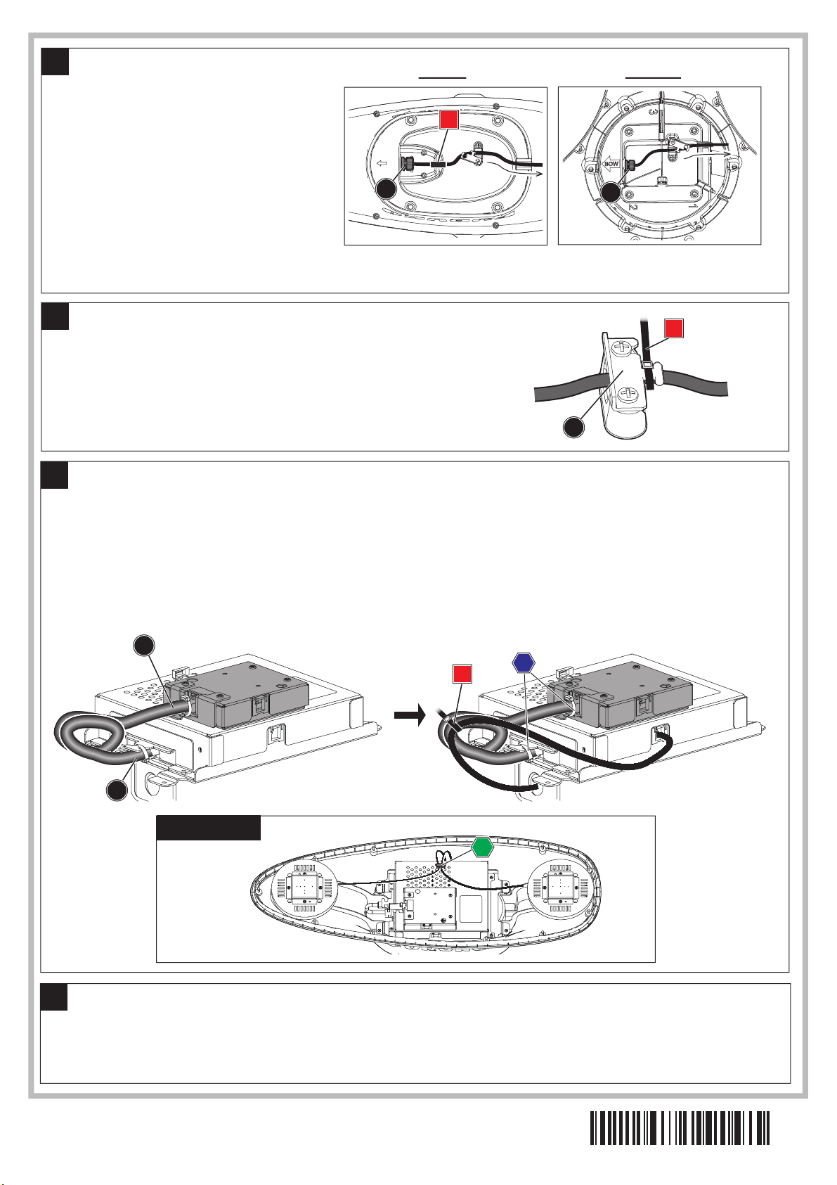
Re-fit the SC-701 cover, then fasten the fast screws to secure the cover.
ᵪᵟᵬᵽᵡᵬᵴ ኵԼỉᵟᵍᵠ ἅἁἑᢿ
1
2
3
B
C
A1
A
B
B1 B1
B2
A2
C
D
A3

Installation for OP20-48 (For SC-703, SC-1303/ ᆰɶዴᢿဇӕ˄Ậ )
Turn the antenna upside-down, then carefully
cut the cable tie at the clamp indicated as“A”.
Unfasten the two screws on the cable clamp, then
remove the cable clamp.
For SC-703, also unfasten the two screws on the
cable cover, indicated as “B”, then remove the
cable cover.
ᆰɶዴᢿửᘻᡉẲềẆἃὊἨἽἁἻὅἩίᵟὸఌΨỉள
ዴἢὅἛửЏụộẴẇἃὊἨἽἁἻὅἩỉἊᵐஜửዼ
ỜềẆἃὊἨἽἁἻὅἩửӕụٳẲộẴẇ
ᵱᵡᵋᵕᵎᵑỉئӳỊẆἃὊἨἽỽἢὊίᵠὸỉἊᵐஜử
ዼỜềẆἃὊἨἽỽἢὊửٳẲộẴẇ
Unfasten and remove the nuts and bush at
“A”. For SC-703, also remove the cable
bush, indicated as “B”. These parts will be
reused. Next, remove the cable gland (C) by
pushing it with your finger.
ᵪᵟᵬἃὊἨἽỉఌΨỆẝỦẐἜἕἚᵏẑẐἨἕἉἷẑẐἜἕ
ἚᵐẑίᵟὸửٳẲộẴẇᵱᵡᵋᵕᵎᵑỉئӳỊẆẐἃὊἨἽ
ἨἕἉἷẑίᵠὸờٳẲộẴẇӕụٳẲẺᢿԼỊẆࢸỂẴ
ỔềဇẲộẴẇẸỉࢸẆἃὊἨἽἂἻὅἛίᵡὸử
ỂẲᡂỚẆٳẲộẴẇ
1
2
Unfasten the six screws on the base of the antenna (SC-703 has 11 screws), then turn the antenna right-side-up. Remove the
top cover. Disconnect the LAN cable from the PCB (indicated as“A”) and remove the cable gland and the gasket (indicated as
“B”, to be re-used). Pull the LAN cable out of the antenna, from the base.
For SC-703, remove the coaxial cable from the locking saddle (indicated as “C”) on the PCB cover.
ᆰɶዴᢿỉࡁᢿỆẝỦἊᵔஜίᵱᵡᵋᵕᵎᵑỉئӳỊᵏᵏஜὸửዼỜềẦỤᆰɶዴᢿửᘙỆᡉẲềẆᆰɶዴᢿỉỽἢὊửٳẲộẴẇؕெẦỤᵪᵟᵬἅ
ἁἑử৷ẟềίᵟὸẆᵪᵟᵬἃὊἨἽɥỉἃὊἨἽἂἻὅἛίᵠὸểἣἕỿὅᵆᵠᵇờٳẲộẴίࢸỂဇὸẇᆰɶዴᢿỉࡁᢿẦỤᵪᵟᵬἃὊἨἽửࡽẨ৷Ẩ
ộẴẇᵱᵡᵋᵕᵎᵑỉئӳẆؕெỽἢὊɥỆẝỦἿἕỿὅἂὁỶἶἇἛἽίᵡὸẦỤӷ᠆ἃὊἨἽửٳẲộẴẇ
3
Unfasten the four screws on the PCB cover, then remove the PCB cover. Fit the locking saddle (”A”, included) to the PCB.
ؕெỽἢὊỉӕ˄ẬἊᵒஜử
ٳẲềẆؕெỽἢὊửӕụٳẲộ
ẴẇؕெỆἿἕỿὅἂỺἕἊἇἛ
ἽίᵟẆӷὸửӕ˄ẬộẴẇ
4
SC-703 SC-1303
SC-703 SC-1303
B
A
AA
B
C
A A
A
BC

Pass the harness from the LAN CONV KIT through the
saddle fitted at step 4, then connect the cables to their
connectors (indicated as “A” and “B”). To avoid interference,
twist the harness connector twice (”A1”) before connecting it to
the “A” connector on the PCB.
ᵪᵟᵬᵽᵡᵬᵴኵԼỆếẟềẟỦἡὊἋửẆᵒỂӕụ˄
ẬẺἿἕỿὅἂỺἕἊἇἛἽửᡫẲềẆؕெɥỉἅἁἑ
ίᵟẆᵠὸỆዓẲộẴẇἅἁἑίᵟὸဇỉἡὊἋỊẆฏ
ݣሊỉẺỜᵐׅỈẳẾềίᵟᵏὸẦỤẆἅἁἑỆዓẲềẪ
ẻẰẟẇ
Re-fit the cover removed at step 4, then loosely thread two binding screws (included) at the locations indicated as “A”. Fit the
LAN CONV KIT (indicated as “B”) to the binding screws, then fasten the screws to secure the kit in place.
Pass the coaxial cable from the kit through the cable entry below the PCB (indicated as “C”).
ᵒỂٳẲẺؕெỽἢὊửӕ˄ẬẆؕெỽἢὊɥỉᵐίᵟὸỆἢỶὅἛݱἊίӷὸửዼẪӕ˄ẬộẴẇؕெɥỆᵪᵟᵬᵽᵡᵬᵴኵԼίᵠὸử᠍Ặ
ềẆᵐỉᆭẦỤἢỶὅἛݱἊửዸỜộẴẇẸỉࢸẆᵪᵟᵬᵽᵡᵬᵴኵԼỆếẟềẟỦӷ᠆ἃὊἨἽửẆؕெɦỉἃὊἨἽӝίᵡὸỆᡫẲộẴẇ
5
The coaxial cable has a thick section (indicated as “A”). Fit the cable gland to edge of the thick area which is closest to the
LAN CONV KIT (indicated as “B1”), then fit the cable gasket (indicated as “B2”). When fitting the cable gland, take care that
the gasket (indicated as “B1”) is fitted correctly (not squashed or wedged between the glands).
NOTE: Do not attach the cable gland on the thin area of the coaxial cable.
7
ᵪᵟᵬᵽᵡᵬᵴኵԼỉӷ᠆ἃὊἨἽỉࢲầٽẪễẾềẟỦᢿЎίᵟẆኖᵏᵓᵎᶋᶋᧈὸɥỂẆᵪᵟᵬᵽᵡᵬᵴኵԼỆỂẨỦẻẬᡈẟˮፗỂẆᵐỂٳẲẺἃὊ
ἨἽἂἻὅἛỉҞЎίᵠᵏὸửӕụ˄ẬộẴẇἣἕỿὅίᵠᵐὸỆẝỦЏụᡂỚửẨẆἃὊἨἽἂἻὅἛỉɶỉἃὊἨἽửỮỂẆἃὊἨἽἂἻὅἛϋỆ
ӓộỦợạỆӕụ˄ẬộẴẇẸỉࢸẆസụỉἃὊἨἽἂἻὅἛҞЎửӕụ˄ẬộẴẇẮỉểẨẆἣἕỿὅỉ֣ỚᡂỚầễẟợạỆදẲềӕụ˄Ậề
ẪẻẰẟẇ
දὸẅἃὊἨἽࢲỉኬẟᢿЎỆἃὊἨἽἂἻὅἛửӕụ˄ẬễẟỂẪẻẰẟẇ
A
B
6
A
Align the flat part (A) of the cable gland
with the cable entry (B), then securely fit the
cable gland to the cable entry.
8
ӕ˄ẬẺἃὊἨἽἂἻὅἛỉỤễᢿЎίᵟὸầ
ἃὊἨἽӝίᵠὸỆӳạợạỆẆẲẾẦụểࠀẲᡂ
ỚộẴẇ
A1
AB
C
B
A
B2
B1
A

Turn the antenna unit upside-down, then
re-fit the nuts and bush removed at step 2 to
the location on the antenna base indicated as
“A”. (Recommended torque: 0.76N•m).
For SC-703, fit the cable bush (indicated as “B”)
to the indent in the antenna base. Next, replace
the cable cover removed at step 1.
ᆰɶዴᢿửᘻᡉẲềẆᵐỂٳẲẺẐἜἕἚᵐẑẐἨἕ
ἉἷẑẐἜἕἚᵏẑίᵟὸửӕụ˄ẬộẴίዸ˄ἚἽἁᾉ
ᵎᵌᵕᵔᵬᶋὸẇ
ᵱᵡᵋᵕᵎᵑỉئӳỊẆẐἃὊἨἽἨἕἉἷẑίᵠὸửἃὊἨἽỽἢὊỉЏụഎẨˮፗỆӕ˄ẬộẴẇẸỉẝểẆᾀỂٳẲẺἃὊἨἽỽἢὊửΨỆ
ẲộẴẇ
9
Turn the antenna unit right-side-up, and attach the cable bush to both connector end of the LAN cable, then between the LAN
COAX CONV KIT and the PCB (indicated as “A”). Loop the excess LAN cable twice , then secure the LAN cable to the
coaxial cable with a cable tie (indicated as “B”) at the lower location than the LAN COAX CONV KIT. Secure the LAN cable to the
two cable clamps (“C”).
For SC-703, secure the cable for both antennas to the locking saddle indicated as “D”.
ᆰɶዴᢿửᘙỆᡉẲẆᵪᵟᵬἃὊἨἽኵԼίӷὸỉἅἁἑɲᇢỆἃὊἨἽἨἕἉἷửӕụ˄ẬẺẝểẆؕெểẸỉɥỆӕụ˄ẬẺᵪᵟᵬᵽᵡᵬᵴኵԼ
ỆዓẲộẴίᵟὸẇᵪᵟᵬἃὊἨἽỉ˷ЎễᧈẰỊᵐࠇẨỆẲềẆᵪᵟᵬ٭ỿἕἚợụ˯ẟˮፗỂẆӷ᠆ἃὊἨἽểσỆளዴἢὅἛίӷὸỂܭ
ẲộẴίᵠὸẇộẺẆᵪᵟᵬἃὊἨἽỊளዴἢὅἛửẾềἃὊἨἽἁἻὅἩᵐίᵡὸỆܭẲộẴẇ
ᵱᵡᵋᵕᵎᵑỉئӳỊẆᵐếỉỴὅἘἜẦỤỉἃὊἨἽửẆἿἕỿὅἂὁỶἶἇἛἽίᵢὸỆܭẲộẴẇ
11
Pass the cable through the cable clamp (indicated as “A”), then fasten the
cable clamp. Secure the cable to the cable clamp at the location indicated
as “B” with a cable tie, then cut any excess cable tie.
ἃὊἨἽἁἻὅἩίᵟᵇỆἃὊἨἽửᡫẲẆἃὊἨἽἁἻὅἩỂܭẲộẴẇ
ἃὊἨἽἁἻὅἩểἃὊἨἽửẆளዴἢὅἛίӷὸỂܭẲộẴẇளዴἢὅἛ
ỉ˷ЎễᧈẰίᵠὸỊЏụộẴẇ
10
ᵑỂٳẲẺᆰɶዴᢿỉỽἢὊửӕụ˄ẬộẴẇ
Re-fit and secure the cover removed at step 3.
12
SC-703 SC-1303
B
AA
B
A
For SC-703
Pub. No. C72-01601-C
(1905, REFU) OP20-47/48
Note: Take care not to crush the anti-fall cord between the antenna cover and base.
දᵇᴾẮỉểẨẆᆰɶዴᢿỽἢὊỆếẟềẟỦӵɦậኜửẆộễẟợạỆẲềẪẻẰẟẇ
A
A
B
D
C
䢲䢲䢲䢳䢻䢴䢶䢳䢵䢳䢴
Table of contents
Other Furuno Media Converter manuals